
Related Manuals for SICK MCS100E


Summary of Contents for SICK MCS100E
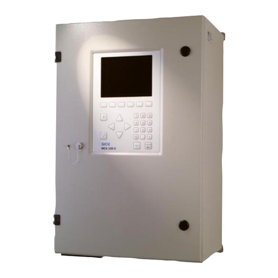
- Page 1 Title Page O P E R A T I N G I N S T R U C T I O N S MCS100E IR Analyzer Commissioning Operation Maintenance...
- Page 2 Original Documents The English version 8009504 of this document is an original document from SICK AG. SICK AG assumes no liability for the correctness of an unauthorized translation. Contacts Guarantee Information Specified product characteristics and technical data do not serve as guarantee declarations.
- Page 3 Risk or hazardous situation which could result in severe personal injury or death. CAUTION Hazard or unsafe practice which could result in less severe or minor injuries and/or property damage. NOTICE Hazard which could result in property damage. MCS100E Operating Instructions 8009504/V YWA7/V3-1/2018-01 © SICK AG...
-
Page 4: Table Of Contents
2.5.1 Data transmission with MCS100E program........20 2.5.2... - Page 5 Program start on MCS100E side........
- Page 6 Safety prompts ............49 MCS100E Operating Instructions 8009504/V YWA7/V3-1/2018-01 © SICK AG...
- Page 7 Show files ............. 90 MCS100E Operating Instructions 8009504/V YWA7/V3-1/2018-01 © SICK AG...
- Page 8 Flow too low ............. . . 114 MCS100E becomes too hot (excess temperature) ......114 MCS100E does not start operation upon power-on .
- Page 9 Operating data............136 MCS100E Operating Instructions 8009504/V YWA7/V3-1/2018-01 © SICK AG...
- Page 10 Contents MCS100E Operating Instructions 8009504/V YWA7/V3-1/2018-01 © SICK AG...
-
Page 11: Important Information
Important information MCS100E Important information Main hazards Main instructions for operation Intended use Own responsibility MCS100E Operating Instructions 8009504/V YWA7/V3-1/2018-01 © SICK AG... -
Page 12: Main Hazards
Channel sample gas off safely (→ p. 24, §3.2.2.1) WARNING: Danger to life/health risks caused by leaks in the gas path If noxious gases are channeled into the MCS100E: A leak in the gas path can create acute danger for persons. -
Page 13: Responsibility Of User
1 . 3 Designated users The MCS100E may be operated by competent persons only who, based on their device- specific training and knowledge of the device as well as knowledge of the relevant regulations, can assess the tasks given and recognize the dangers involved. - Page 14 Important information MCS100E Operating Instructions 8009504/V YWA7/V3-1/2018-01 © SICK AG...
-
Page 15: Product Description
Product description MCS100E Product description Product identification Functional principle Characteristics Variants MCS100E Operating Instructions 8009504/V YWA7/V3-1/2018-01 © SICK AG... -
Page 16: Product Identification
The type plate is located on the top of the right side of the housing. Description 2. 2 The MCS100E measuring device is used for extractive continuous and selective measurement of emissions (e.g.: HCl, NH O, CO, SO , NO ) of incineration plants. -
Page 17: Design
• Cell (optical path length dependent on application) • Flow meter • O sensor (optional) • Computer and electronics Figure 2 MCS100E setup User interface Photometer Flow meter sensor (optional) Computer Cell Sample gas outlet Sample gas inlet Interfaces MCS100E Operating Instructions 8009504/V YWA7/V3-1/2018-01 © SICK AG... -
Page 18: Measuring Principle
Product description Measuring principle 2.2.2 MCS100E is a single-beam infrared photometer that works on the basis of the transmitted light measuring technique applying the single-beam dual-wavelength method and the gas filter correlation method. Figure 3 Measuring principle Light source Cell... -
Page 19: O 2 Sensor (Option)
Ambient air which reaches the cell by diffusion is used as reference gas. Barometric pressure compensation (option) 2.2.7 Barometric pressure compensation for the MCS100E is available as an option. Interfaces 2.2.8 Fiber optics interfaces •... -
Page 20: Data Storage
Data transmission with MCS100E program 2.5.1 The MCS100E program must be installed on the external PC. File transfer is carried out via the MCS100E menus (→ p. 90, §5.7.15.4 and → p. 91, §5.7.15.5). Connection of external PC: • Optical (fiber optics) (→ p. 27). -
Page 21: Qal3 (Din En 14181)
Use of the calibration filter option 2.7.2 As an option, the MCS100E HW measuring device can be equipped with a third filter wheel which allows to swivel-in so-called calibration filters (→ p. 17, Figure 2). This function can either be started program-controlled or manually using the MCS100E standard software. - Page 22 Product description MCS100E Operating Instructions 8009504/V YWA7/V3-1/2018-01 © SICK AG...
-
Page 23: Installation
Installation MCS100E Installation Project planning Transport Setup Installation Initial commissioning MCS100E Operating Instructions 8009504/V YWA7/V3-1/2018-01 © SICK AG... -
Page 24: Transport
Lay the sample gas outlet running downwards so that no condensate is accumulated. If necessary, provide for a suitable condensate collecting device and adequate ventilation. Protect the measuring gas outlet from frost. MCS100E Operating Instructions 8009504/V YWA7/V3-1/2018-01 © SICK AG... - Page 25 - No O sensor sensor - No external FID AND/OR - Branch current to external - External FID 4 Place cell cover in position and tighten screws. 5 Check sample gas lines for leaks. MCS100E Operating Instructions 8009504/V YWA7/V3-1/2018-01 © SICK AG...
-
Page 26: Interfaces
Installation Interfaces 3.2.3 Optical interfaces 3.2.3.1 The optical connections are located at the bottom of MCS100E. Connecting the fiber optical cables: ⊗ Do not sharply bend the fiber optical cables. • Minimum bending radius: 3 cm. • The direction of the fiber optical cable can be as desired. - Page 27 • The following equipment can be connected to the “Printer/PC” interface: – Printer or PC • Designation of the connections on the MCS100E: “Printer/PC” “E” or “S” (E = receiver, S = sender) • Maximum length of fiber optical cables: 50 m (unless required differently by the receiver) •...
-
Page 28: Electric Serial And Parallel Interface (Option)
– Protocol: UDP – Connector: RJ 45 – Cable: Cross-over on PC, 1:1 on hub – Data format: 10 MBit half-duplex – Addresses (preset): - IPADDRESS:192.168.0.x (see label on Ethernet interface) - SUBNETMASK:255.255.255.0 MCS100E Operating Instructions 8009504/V YWA7/V3-1/2018-01 © SICK AG... -
Page 29: Remote Control
- IP_ROUTER: 192.168.0.1 Call-up: TSETUP 192.168.0.1 255.255.255.0 192.168.0.1 Is it OK? [y,n] : <y> <ENTER> (saved in “C:\NOVELL\CLIENT32\NET.CFG”). 5 Switch off the MCS100E. Then automatic start when the MCS100E is switched on. MCS100E Operating Instructions 8009504/V YWA7/V3-1/2018-01 © SICK AG... -
Page 30: Program Start On Pc Side
4 If you only want to view the TINY window: - Start the Windows version of Java. - Using a text editor, enter the IP address of MCS100E and display the path of the “javaw” program to your Java installation in “Properties” of “Link”. -
Page 31: Modem With The Netop Program
NetOP software (Part No. 6029452). Connection on MCS100E side 3.3.2.1 1 Connect the RS232C interface of MCS100E (→ p. 28, Figure 8) to the modem. The modem setting cannot be changed. 2 Connect the modem to the telephone network (analog). -
Page 32: Program Start On Pc Side
→ Procedure: documentation supplied with the delivery. – “Quick DIAL” Specify the telephone number of the MCS100E telephone connection (comma for “Wait time”) – The screen content of the MCS100E is shown. File transfer via modem → p. 33, §3.4.2 Terminating the transfer 3.3.2.5... -
Page 33: Data Transfer To/From External Pc
1 Install the fiber optical cable connection (→ p. 27, Figure 6). 2 The MCS100E measurement program must be installed and running on the PC (1.bat). 3 Start the desired data transfer on the MCS100E (for example → p. 86, §5.7.11.14, → p. 90, §5.7.15.4, → p. 91, §5.7.15.5). -
Page 34: Modbus Communication Protocol
– IBM-compatible computer with 386 CPU – 1 MB DRAM – 2 MB disk for internal programs – 2 MB memory extension (required for data saving)) Hardware requirements for printer 3. 7 • V24 interface • IBM-compatible. MCS100E Operating Instructions 8009504/V YWA7/V3-1/2018-01 © SICK AG... -
Page 35: Electrical Installation
Electrical installation 3 . 8 As soon as the power plug is connected to line power, MCS100E automatically starts operation (→ p. 38, §4.1). Before connecting the power plug to the line power, ensure that all necessary installation work has been done. -
Page 36: Power Fuses
Installation Power fuses 3.8.1.2 1 Put MCS100E out of operation (→ p. 100, §6.1) 2 Remove power plug (otherwise the fuse holder cannot be opened) • The fuse holder is inside the power plug housing. Figure 15 Fuse holder Fuse holder 3 To remove the fuse holder, press the two notches at the sides and pull out. -
Page 37: Commissioning
Commissioning MCS100E Commissioning Preparation Power-on procedure Function test MCS100E Operating Instructions 8009504/V YWA7/V3-1/2018-01 © SICK AG... -
Page 38: Commissioning
The heating-up time of MCS100E is approx. 4 h. Do not apply condensing gas to the instrument before the end of the heating-up time. For connection to line power, a grounded cord connector is used (the MCS100E does not have a power switch). Figure 16... -
Page 39: External Keyboard
(→ p. 109, §7.8). 4 Start the “Norton Commander” at DOS level with: <c:\nc> Note: Switch MCS100E off and on again before selecting the “Norton Commander”. 5 In the “Autoexec.bat” file (<F4>): – Insert “rem(blank)” before the line with the previous language and –... - Page 40 Commissioning MCS100E Operating Instructions 8009504/V YWA7/V3-1/2018-01 © SICK AG...
-
Page 41: Operation
Operation MCS100E Operation Operation Status messages MCS100E Operating Instructions 8009504/V YWA7/V3-1/2018-01 © SICK AG... -
Page 42: User Interface
The <ESC> key is used to quit the menus, to terminate the program, to cancel a command, etc. If modifications were entered you will be prompted whether to save or not. <ENTER> key The <ENTER> key is used to open a menu, to confirm entries, etc. MCS100E Operating Instructions 8009504/V YWA7/V3-1/2018-01 © SICK AG... -
Page 43: Entering Alphanumerical Characters
2 Keep pressing function key F8 until the required character is displayed in the function key fields. 3 Press the function key which is positioned below the required character. It is best to use an external keyboard for entering characters (→ p. 39, §4.2). MCS100E Operating Instructions 8009504/V YWA7/V3-1/2018-01 © SICK AG... -
Page 44: Data And Program Storage
Data and program storage 5. 2 Structure of directories 5.2.1 The MCS100E software is located in a directory of its own, containing: • The configuration program • The measurement program (1.bat) itself • The text and help files (.txt and .hlp) •... -
Page 45: Starting The Measurement Program
5 . 3 MCS100E starts the measurement program and thus measurement: • Automatically when MCS100E (→ §5.3.1) is switched on. • AT DOS level by means of the 1.bat program (→ §5.3.2). After the start of the measurements, the measured value display is shown. -
Page 46: Stopping And Starting Measurement
3 You are then at DOS level. 4 If required, disable the watchdogs (→ p. 109, §7.8). To be sure that - after having quit the program - MCS100E is in the basic condition (important e.g. for configuration of the I/O module boxes): ... -
Page 47: Status Bars
– If there are several active status messages, they are displayed successively (each message for approx. 4 seconds). – The texts associated to the status bars are programmed in the menu Specialist: System edit: Message and corresp. relays. MCS100E Operating Instructions 8009504/V YWA7/V3-1/2018-01 © SICK AG... -
Page 48: Using The Menus
In file selection lists 5.6.3 Change sorting algorithms <–> or <+> Go to top margin line <> (arrow key left) Tag files <Space key> Edit tagged files <ENTER> Reject entries <ESC> MCS100E Operating Instructions 8009504/V YWA7/V3-1/2018-01 © SICK AG... -
Page 49: Safety Prompts
Starting from the “Yes” field, the No/Cancel field will only be displayed when pressing “once the arrow key, right”. If the safety prompt is not answered within 120 seconds, then it will automatically be answered “No”. MCS100E Operating Instructions 8009504/V YWA7/V3-1/2018-01 © SICK AG... -
Page 50: Menus
Operation Menus 5. 7 Main menu 5.7.1 Specialist: System edit 5.7.2 Specialist: Utilities 5.7.3 MCS100E Operating Instructions 8009504/V YWA7/V3-1/2018-01 © SICK AG... -
Page 51: Specialist: Utilities: Service: Environment Configuration
Operation Specialist: Utilities: Service: Environment configuration 5.7.4 MCS100E Operating Instructions 8009504/V YWA7/V3-1/2018-01 © SICK AG... -
Page 52: Display Graphic
• Further 8 components as lines only. Measurement sequence Start time of File File size Free Time at (= system) measurement space on hard disk cursor position Measure- ment range Measured value MCS100E Operating Instructions 8009504/V YWA7/V3-1/2018-01 © SICK AG... - Page 53 6: If “Current“: Cursor to end of data recording. If “Archive“: Data display until end of screen <F8> Menu with: - Archive values - Time axis - Bar graph <ESC>: Create new scale for graphic <ESC> Quit graphic. MCS100E Operating Instructions 8009504/V YWA7/V3-1/2018-01 © SICK AG...
-
Page 54: Graphic Output: Bar Graph
<ESC>: Create new scale for graphic <ESC> Quit graphic. At the end of a data file the next file in chronological order is opened automatically and the data continues to be displayed. MCS100E Operating Instructions 8009504/V YWA7/V3-1/2018-01 © SICK AG... -
Page 55: Diagnosis
1: Current value < NOMINAL VALUE-limit low 0: Limit not exceeded ALARM 1: Current value > nominal value+limit high remains set until RESET is carried out Additional information and settings --> menu: Specialist: System edit: Temperatures and Pressure MCS100E Operating Instructions 8009504/V YWA7/V3-1/2018-01 © SICK AG... -
Page 56: Messages
These messages are output automatically to the printer, if the printer is active (Main Menu: Printer: Print on-line: Protocol Start). The latest message is stated at the top. Up to 192 messages are stored. MCS100E Operating Instructions 8009504/V YWA7/V3-1/2018-01 © SICK AG... -
Page 57: Print (On/Off)
Note: The separators of date and time should be different to enable an evaluation program to find a distinguishing feature. File extension for the protocol files is ”.txt”. Protocol files can be edited in the usual table calculation programs. Protocol changes are executed immediately. MCS100E Operating Instructions 8009504/V YWA7/V3-1/2018-01 © SICK AG... -
Page 58: Print Archive (Name)
5 types of protocols can be created and given a name - to ease identification. The entries to be made correspond to those for the on-line protocol, however, the protocol of archived data can additionally be output to a file or to the screen. MCS100E Operating Instructions 8009504/V YWA7/V3-1/2018-01 © SICK AG... -
Page 59: Protocol Start
Before starting the output, make sure to terminate current on-line output, if necessary. Protocol output of stored data is started. Output can be interrupted with <ESC>. MCS100E Operating Instructions 8009504/V YWA7/V3-1/2018-01 © SICK AG... -
Page 60: Print Diagnosis
Main Menu: Printer: Print System data A list is displayed for selection of the MCS100E data to be printed. Upon selection of the system data you will be prompted whether or not to start printing. If you wish to print into a file, then you have to indicate the file name when prompted. -
Page 61: Configuration
0: No relay to be assigned - Number: Inverted setting Current 0..20 mA 4..20 mA Max. 32 outputs can be activated. The menu option is identical to Specialist: System edit: Signal output MCS100E Operating Instructions 8009504/V YWA7/V3-1/2018-01 © SICK AG... -
Page 62: Graphic Output
The texts are displayed in the same order as defined in Specialist: System edit: Message and corresp. relays. The free relays and texts are defined in the menu Specialist: System edit: Messages and corresp. relays MCS100E Operating Instructions 8009504/V YWA7/V3-1/2018-01 © SICK AG... -
Page 63: Calibration Gases
The drift with the Zero resp. calib. gas sampling control is automatically entered here. range): Last: Drift since last control Total: Drift since first control, e.g. last service These values are also displayed in the main menu option “Diagnosis”. MCS100E Operating Instructions 8009504/V YWA7/V3-1/2018-01 © SICK AG... - Page 64 Start CALIB with 2 points The same as for point 1, but the 2 test gas follows after the 1 test gas. Set default values “Yes”: Default values are set. MCS100E Operating Instructions 8009504/V YWA7/V3-1/2018-01 © SICK AG...
-
Page 65: Zero/Calib/Purge Programs
Duration of the backpurge pulse Relays The pulse triggers the relay defined here. At the end of a backpurge program the relay is always set to the rest state. (No entries possible in this menu.) MCS100E Operating Instructions 8009504/V YWA7/V3-1/2018-01 © SICK AG... -
Page 66: Sample Switching
5.7.9.7 Main Menu: Configuration: Sample switching With MCS100E sample (point) switching is possible.by switching cyclically from one sample point to the next. The system is pre-purged for a selectable time with the new sample gas, before the new measured value is accepted. -
Page 67: Specialist Menus
Password for the specialist level 5.7.10.1 To edit the specialist level, a password has to be entered. The password input is not displayed on the screen. Definition of password: → p. 121, §9.1.3.1 MCS100E Operating Instructions 8009504/V YWA7/V3-1/2018-01 © SICK AG... -
Page 68: System Edit (Name)
0: No relay to be assigned - Number: Inverted setting Current 0..20 mA 4..20 mA Max. 32 outputs can be activated. The menu option is identical to Main Menu: Configuration: Signal output MCS100E Operating Instructions 8009504/V YWA7/V3-1/2018-01 © SICK AG... -
Page 69: Graphic Output
Lower status bar, flashing: Warning or alarm Upper status bar, not flashing: Operational state Text Text, displayed in the status bar The relays can also be assigned in the main menu Main Menu: Configuration: Message and corresp. relays. MCS100E Operating Instructions 8009504/V YWA7/V3-1/2018-01 © SICK AG... -
Page 70: Calibration Data
1: One table can be entered 0: No LIN table to be calculated Span gas conc. Span gas concentration of the span gas connected (enter). Internal standard: Nominal concentration of internal standard (enter) MCS100E Operating Instructions 8009504/V YWA7/V3-1/2018-01 © SICK AG... - Page 71 Equivalent to calibration factor (see above in this Table) internal Calibration factor for internal adjustment standard Drift total ZERO Drift (zero gas) since last drift reset (e.g. after service) Drift last ZERO Drift (zero gas) since last drift correction MCS100E Operating Instructions 8009504/V YWA7/V3-1/2018-01 © SICK AG...
- Page 72 1 test gas. Set default values “Yes“: Default values are set. From this menu, the specifications in the menu “Main Menu: Diagnosis and Main Menu: Configuration: Span gases are derived. MCS100E Operating Instructions 8009504/V YWA7/V3-1/2018-01 © SICK AG...
-
Page 73: Zero/Calib/Purge Programs/Other Programs
As of the start of the program, the analog output is held for this period in minutes and then released. 0: Analog output is not held. Average at minutes Average from this time until final time. (This makes it possible to wait for rise times.) MCS100E Operating Instructions 8009504/V YWA7/V3-1/2018-01 © SICK AG... - Page 74 Ti =t: Timer i equal to t Ti <t: Timer i smaller than t Timers 1..100 are set to zero during start of program. Timers 101..116 resume operation after start of program as well as after “Power On“ MCS100E Operating Instructions 8009504/V YWA7/V3-1/2018-01 © SICK AG...
- Page 75 Go on only if condition is not met Condition is “true”, if transition of flag is from “false” to “true“ Condition is “true”, if transition of flag is from “true” to “false“ Commands, upon setting only MCS100E Operating Instructions 8009504/V YWA7/V3-1/2018-01 © SICK AG...
-
Page 76: Sample Switching
5.7.11.6 Specialist: System edit: Sample switching With MCS100E, sample (point) switching is possible by switching cyclically from one sample point to the next. The system is pre-purged for a selectable time with the new sample gas, before the new measured value is accepted. -
Page 77: Results
R1..R14: Sample components 1..14 R15: Flow meter R16: O sensor R17..R24: Analog inputs 1..8 R25..R32: Temperatures Upon receipt via Modbus protocol: () “Results” Ri = “Formula” Ri) AIi: Analog input channel (i = 1..32) MCS100E Operating Instructions 8009504/V YWA7/V3-1/2018-01 © SICK AG... - Page 78 Mean square fit data, e.g. CAL (R3,1) Calculation with result 3 as input signal for table 1. R25..R32 are equivalent to TPA1..TPA8 (see secondary variable TPAi) Note: Sample point index “0” means: Active sample points MCS100E Operating Instructions 8009504/V YWA7/V3-1/2018-01 © SICK AG...
-
Page 79: Definition Of Components
Setting Meaning Is there an aperture at Yes: MCS100E avoids a filter wheel position where there are 2 subsequent position 8 of filter wheel 1 empty apertures (overload of detector) by first positioning filter wheel 2 on a filter and then filter wheel 1 on an empty aperture. -
Page 80: Linearization Tables
Example for a 4 .. 22 mA analog input: 0 .. 4095 Digits correspond to 0 .. 22 mA Measured value required: 0 at 4 mA and MaxValue at 20 mA Table entries Absorbance Concentration 3724 MaxValue MCS100E Operating Instructions 8009504/V YWA7/V3-1/2018-01 © SICK AG... -
Page 81: Interference Table
Display actual value (in Abs. or Conc., depending on IF Component). <ENTER>: Accept displayed value. Represent linearization curve graphically. The numerical display corresponds to the pairs of values from the table. Key 3: Change scales. MCS100E Operating Instructions 8009504/V YWA7/V3-1/2018-01 © SICK AG... -
Page 82: Limit Values
Values falling below or exceeding the limit can be interrogated in Specialist: System edit: Zero/Calib/Purge/other programs with the variables AH, AL, WH, WL. There is no hysteresis. The limits with a mark () are verified. MCS100E Operating Instructions 8009504/V YWA7/V3-1/2018-01 © SICK AG... -
Page 83: Temperatures And Pressure
ERROR reset Hysteresis = 5 °C Limit = 12 °C 197 °C Limit 190 °C Hysteresis Nominal (=set value) 185 °C Hysteresis 180 °C Limit 173 °C Heating on ERROR set ERROR reset MCS100E Operating Instructions 8009504/V YWA7/V3-1/2018-01 © SICK AG... - Page 84 RESET is carried out. The relay is interrogated in Specialist: System edit: Zero/Calib/Purge/other programs. For RESET the error message ER 32 (Specialist: System edit: Zero/Calib/Purge programs/other programs is used. Only measurement, inputs are not processed MCS100E Operating Instructions 8009504/V YWA7/V3-1/2018-01 © SICK AG...
-
Page 85: Protocol Definition
File extension for the protocol files is ”.txt”. Protocol files can be edited in the usual table calculation programs. The printer protocol settings Main Menu: Printer: Print Archive Protocol Definition and Specialist: System edit: Protocol Definition are identical. MCS100E Operating Instructions 8009504/V YWA7/V3-1/2018-01 © SICK AG... -
Page 86: Data Storage And Send To Pc
MCS only on request: MCS100E sends data to the serial interface on request, only. MCS100E is continuously ready for receiving data. MCS on request and in cycles: MCS100E sends data on request and in cycles to the serial interface. MCS100E is continuously ready for receiving data. -
Page 87: Softkey Menu Definition
When pressing <ENTER>, a list containing the 32 possible menu windows is presented. Select requested window with <ENTER>. Note: If a sub-menu window is open in the graphic, then the graphics display is not updated. MCS100E Operating Instructions 8009504/V YWA7/V3-1/2018-01 © SICK AG... -
Page 88: Mean Square Fit Data
<ENTER>: Accept displayed value. Operator's Notebook 5.7.11.17 Specialist: System edit: Operator's Notebook The names listed in the operator’s notebook are only used as a memory aid when entering programs or when printing etc. MCS100E Operating Instructions 8009504/V YWA7/V3-1/2018-01 © SICK AG... -
Page 89: System, Select For Editing
(the new measurement sequence) becomes active, and the old system is deactivated automatically. The system (=measurement sequence) started when calling in the MCS100E program is derived from the configuration file MCSCONF, menu: Directories and Files (→ p. 123, §9.1.3.4). -
Page 90: Utilities
5.7.15.2 Specialist: Utilities: Files, copy This menu is used to copy files on the hard disk of the MCS100E. After having marked the files (using the space key) and subsequent confirmation with <ENTER>, you are prompted to enter the “destination path“... -
Page 91: Receive Files From Pc
This menu is used to copy files from an external PC. In Specialist: Utilities: Service: Environment Configuration: Interfaces, the PC interface must be configured. The MCS100E measurement program must also be in operation on the external PC. After having marked the files (using the space key) and subsequent confirmation with <ENTER>, you are prompted to enter the “destination path“... -
Page 92: Service (Test)
Correct in Directories and Files (→ p. 123, §9.1.3.4) and subsequently start measurement program anew (1.bat) The language used when calling in the MCS100E program is derived from the configuration file MCSCONF, menu: Directories and Files (→ p. 123, §9.1.3.4). If you wish another language to be activated upon program start, then you must enter this there. - Page 93 • Graphic • Temporary files are interrogated one after the other. The structure of the directories used when calling in the MCS100E program is derived from the configuration file MCSCONF, menu: Directories and Files (→ p. 123, §9.1.3.4). If you wish another directory structure to be activated upon program start, then you must enter this there.
- Page 94 Interrupt assignment is a default setting (dependent on the hardware configuration) and has to be modified in certain individual cases. Default setting: Can also be assigned to LPT 1/2. If used by COMi: LPTi disable Reserved for I/O module box MCS100E Operating Instructions 8009504/V YWA7/V3-1/2018-01 © SICK AG...
- Page 95 5.7.15.7.4 Specialist: Utilities: Service: Dialogue heat control Dialogue with heat control: Only for service purposes ASCII - Hex - switch-over: ALT H Echo ON/OFF: ALT E Menu exit: F2 or ALT X MCS100E Operating Instructions 8009504/V YWA7/V3-1/2018-01 © SICK AG...
- Page 96 Specialist: Utilities: Service: STOP, START measure Only for service purposes Upon measurement “STOP”, all interfaces (e.g. internal LPM40, I/O module boxes) are deactivated. Upon measurement “START”, all interfaces are re-initialized and the measurement sequence is started. MCS100E Operating Instructions 8009504/V YWA7/V3-1/2018-01 © SICK AG...
-
Page 97: Display, Digital Status
Unit of component Display, digital status 5.7.15.8 Specialist: Utilities: Service: Display, digital status This menu shows the digital status (digital inputs/outputs, relays, flags, timer) of MCS100E. Settings Status “not set” Status “set” MCS100E Operating Instructions 8009504/V YWA7/V3-1/2018-01 © SICK AG... - Page 98 Operation MCS100E Operating Instructions 8009504/V YWA7/V3-1/2018-01 © SICK AG...
-
Page 99: Decommissioning
Decommissioning MCS100E Decommissioning Switch off Disassembly Storage Disposal MCS100E Operating Instructions 8009504/V YWA7/V3-1/2018-01 © SICK AG... -
Page 100: Switch Off
Decontaminate the cell. 1 Purge the MCS100E with inert gas for min. 1 h. 2 Exit the measurement program (→ p. 46, §5.4.2). 3 If necessary, unplug voltage plug resp. disconnect MCS100E from power supply at all poles. Disassembly 6. -
Page 101: Maintenance
Maintenance MCS100E Maintenance Maintenance plan Maintenance work Preventative maintenance Recommended spare parts MCS100E Operating Instructions 8009504/V YWA7/V3-1/2018-01 © SICK AG... -
Page 102: Maintenance Intervals
Check and adjust the flow monitor zero point → p. 104, §7.5 Span gas feeding Maintenance by Customer Service Maintenance by Customer Service w = weekly, q = quarterly, y = yearly Recommended, depending on application MCS100E Operating Instructions 8009504/V YWA7/V3-1/2018-01 © SICK AG... -
Page 103: Visual Check Of The Mcs100E
As required The fan is located on the underside of the MCS100E. It is not necessary to switch the MCS100E off to replace the filter pad. Risk of soiling. Operate the MCS100E without filter pad only for a short period. -
Page 104: Span Gas Feeding
– In the Specialist menu: System edit: Set Calibration data xxxx “Factor” – In the Specialist menu: Utilities: Service: Control Detector unit When the drift is above the specification (see Technical Data): Please contact SICK Customer Service. MCS100E Operating Instructions 8009504/V YWA7/V3-1/2018-01 © SICK AG... -
Page 105: Programming The Measurement Sequence (Overview)
Menu: Specialist: System edit: Graphic output 7 Define analog outputs Leave the extension of analog outputs to SICK Customer Service. Note: Do not simply append the new component at “the rear”. Program the components in the same sequence as defined in “Results”. -
Page 106: Concentration Determination
Maintenance Concentration Determination 7.6.1 The following diagram shows the concentration determination of MCS100E Figure 21 Concentration Determination MCS100E Operating Instructions 8009504/V YWA7/V3-1/2018-01 © SICK AG... -
Page 107: Definition Of Components And Calibrating A System
Pre-defined Assignment of Components, Results and Tables Component Result Lin. Table IF table Max. 24 Max. 64 Max. 16 Max. 64 1..4 5..8 free from 1..16 free from 1..64 free from 1..16 free from 1..64 MCS100E Operating Instructions 8009504/V YWA7/V3-1/2018-01 © SICK AG... -
Page 108: Addresses And Assignment Of The Input Variables
Please write down the board addresses, as a board can loose its address in case of a possible fault. You will find the pre-assigned addresses in your system documentation. MCS100E Operating Instructions 8009504/V YWA7/V3-1/2018-01 © SICK AG... -
Page 109: Parameters At Program Start
Disable the CPU watchdog after quitting the program with DOS command <WDOG disable> or program <8> (8.bat). Enabling the CPU watchdog Enable the CPU watchdog with parameter “WDT” when calling up the program (→ p. 109, §7.7) or command <WDOG ENABLE>. MCS100E Operating Instructions 8009504/V YWA7/V3-1/2018-01 © SICK AG... -
Page 110: Watchdog For Communication
This watchdog cannot be disabled. By removing a jumper it is possible to stop enabling the reset to the CPU. Procedure • Put the MCS100E out of operation (→ p. 100, §6.1) and disconnect from the power supply. • Open the MCS100E. -
Page 111: Load Program From External Pc
PC to parallel interface (For specially trained personnel, only) Connect an external PC to the internal parallel interface of MCS100E using a “DOS- Interlink” cable (connection cable with 11 cores) and copy files by means of a data transfer program. - Page 112 Maintenance MCS100E Operating Instructions 8009504/V YWA7/V3-1/2018-01 © SICK AG...
-
Page 113: Troubleshooting
Troubleshooting MCS100E Troubleshooting General malfunctions Malfunction messages Display messages Measurement errors MCS100E Operating Instructions 8009504/V YWA7/V3-1/2018-01 © SICK AG... -
Page 114: Adjust The Monitor
• Adjust the monitor (→ p. 39, §4.4). • The monitor has a screen saver function. The monitor is automatically switched off after approx. 4 h Press any key on the MCS100E operating panel to switch the screen on again. Flow too low 8. 2 ... -
Page 115: No Contact With Printer/Pc Resp. I/O Module Boxes
Fuses, jumpers and LEDs 8 . 8 WARNING: Electrical hazard When the MCS100E is in operation, line power voltages are present within the instrument. Before performing work inside the MCS100E: Unplug power plug resp. disconnect instrument from power at all poles. -
Page 116: Internal Voltage Control (Lpm40)
LEDs for voltage control SI 2: 2.5 AT for +15 V LED is on if voltage is correct SI 3: 1 AT for –15 V SI 4: 2.5 AT for +24 V MCS100E Operating Instructions 8009504/V YWA7/V3-1/2018-01 © SICK AG... -
Page 117: Heating Controller (Lpm42)
Lights during heating cycle - Bridge open: 230 V LED is OFF Red LED - Bridge closed: 115 V heating safety relay LED is ON Always on Fuse for O heating 1 AT MCS100E Operating Instructions 8009504/V YWA7/V3-1/2018-01 © SICK AG... -
Page 118: Error Messages On The Screen
Error messages on the screen 8. 9 Many functions of the MCS100E are controlled by its internal computer. Error messages are displayed in plain text on the screen. In most cases you will not be able to remedy these errors yourself. If necessary, contact the SICK customer service. -
Page 119: Utility Programs And Protocols
Utility programs and protocols MCS100E Utility programs and protocols MCSCONF ACQINIT PC protocol Modbus protocol MCS100E Operating Instructions 8009504/V YWA7/V3-1/2018-01 © SICK AG... -
Page 120: Mcsconf
Leave changes of the MCSCONF to trained personnel. The configuration software is in the same directory as the MCS100E software. The operation of the configuration program is equivalent to that of the MCS100E measurement program. Start of the configuration program 9.1.1... -
Page 121: Menus
Default setting of serial buffer: 1024 bytes. Maximum size that can be set: 64 Kbytes. If the buffer memory reserved is exceeded during measurement, then MCS100E: • Generates an acoustic warning signal. • The message “Faulty sequence” is presented in the menu option “Messages”. -
Page 122: Text Mode
If the cursor is not moved within the selected dead time while the current measured values are displayed, it automatically jumps to the end of the graphics display. Default setting: 10 seconds. MCS100E Operating Instructions 8009504/V YWA7/V3-1/2018-01 © SICK AG... -
Page 123: Directories And Files
The language of the text file can temporarily be changed in the MCS100E measurement program. (Specialist: Utilities: Service: Environment Configuration : TEXT file) Help file The language of the help file specified here is used upon start of the MCS100E measurement program. The corresponding files are identified as: M1Exxx.HLP whereby xxx e.g. -
Page 124: Acqinit
Description of program ACQINIT Operating Instructions “I/O Module Box”. Exemplary configuration 1 Go to the DOS level at MCS100E. (→ p. 46, §5.4.2). 2 Disable watchdogs (→ p. 109, §7.8) 3 Set all I/O module boxes to the “inactive” mode. - Page 125 10 Before starting the MCS measurement program make sure that all of the green LEDs are lit continuously. 11 Reconnect the jumper of the watchdog at the “left” (→ p. 110, §7.8.2). 12 Enter via the MCS100E keyboard: 1 <ENTER>. The MCS100E measurement program starts again. MCS100E Operating Instructions 8009504/V YWA7/V3-1/2018-01 © SICK AG...
-
Page 126: Modbus Protocol
¦ ¦ ¦Timeout for new Modbus message (*55ms) ¦ ¦ ¦ +------------------------------------------------------------------------------+ Datatransfer MCS100E <---> PC with serial interface and Modbus RTU protocol Start the message with a silent of at least 3.5 character times Byte address function data last-1... - Page 127 0001 .. 0099Result Block 1 : Result 01..32 0101 .. 0199 Result Block 2 : Result 33..64 0201 .. 1400 Component data block 1401 .. 1421Modbus system parameter block 1501 .. 2945Datalog block MCS100E Operating Instructions 8009504/V YWA7/V3-1/2018-01 © SICK AG...
- Page 128 [06] : n2 - LSB No of Registers [07] : no byte - No of data bytes [08] : data - data [xx] : CRC - LSB CRC [xx] : CRC - MSB CRC MCS100E Operating Instructions 8009504/V YWA7/V3-1/2018-01 © SICK AG...
- Page 129 Result 60 0161 0162 Float Result 61 0163 0164 Float Result 62 0165 0166 Float Result 63 0167 0168 Float Result 64 0169 0169 Result 49 Result 49..64 in integer for Timer MCS100E Operating Instructions 8009504/V YWA7/V3-1/2018-01 © SICK AG...
- Page 130 PCalVc 0943 0943 Gain Level Reference Signal GiRef 0944 0944 Gain Level Measure Signal GiMes 0945 0946 Float Measure Range 1 RngUp[1] 0947 0948 Float Measure Range 2 RngUp[2] 0949 0950 Reserved MCS100E Operating Instructions 8009504/V YWA7/V3-1/2018-01 © SICK AG...
- Page 131 (1..31) read and write 1503 1503 hour (0..23) read and write 1504 1504 Reserve 1505 1505 1.value hour:00 read only 1506 1506 2.value hour:01 read only 1564 1564 60.value hour:01 read only MCS100E Operating Instructions 8009504/V YWA7/V3-1/2018-01 © SICK AG...
- Page 132 Utility programs and protocols MCS100E Operating Instructions 8009504/V YWA7/V3-1/2018-01 © SICK AG...
-
Page 133: Specifications
Specifications MCS100E Specifications Declaration of conformity Approvals Parameter lists Technical Data MCS100E Operating Instructions 8009504/V YWA7/V3-1/2018-01 © SICK AG... -
Page 134: Conformity
• EN 61326, Electrical equipment for measurement technology, control technology and laboratory use - EMC requirements For MCS100E in the emission measuring system MCS100E HW: • EN 14181, Calibration of continuously operating emission measuring devices • EN 15267-3: Certification of automatic measuring systems - Part 3 Electrical protection 10.1.1... -
Page 135: Technical Data
Specifications Technical Data 1 0. 2 Dimension drawing 10.2.1 Figure 25 Dimension drawing MCS100E Operating Instructions 8009504/V YWA7/V3-1/2018-01 © SICK AG... -
Page 136: Operating Data
Specifications Operating data 10.2.2 The MCS100E equipment depends on the application. Please see the system documentation enclosed with the MCS100E for the configuration Measured value recording Measuring principle Infrared photometer Dual frequency and gas filter correlation method Spectral range 1 .. 16 μm Number of measuring components Max. - Page 137 (RS232) (optional) Not possible in combination with Ethernet interface Not possible in combination with parallel interface Sample gas (requirements) Composition Only the sample gas composition designed for the MCS100E (→ system documentation) Temperature Application-dependent Thermostatically controlled to cell temperature Max. temperature: 200 °C...
- Page 138 - Printer ........60 MCS100E Operating Instructions 8009504/V YWA7/V3-1/2018-01 © SICK AG...
- Page 139 - Print on-line ......57 MCS100E Operating Instructions 8009504/V YWA7/V3-1/2018-01 © SICK AG...
- Page 140 - Initialisation of I/O modules ....96 - Measuring signal settings ....97 MCS100E Operating Instructions 8009504/V YWA7/V3-1/2018-01 © SICK AG...
- Page 141 ZrO2 sensor ....... . 19 MCS100E Operating Instructions 8009504/V YWA7/V3-1/2018-01 © SICK AG...
- Page 142 E-Mail sales@sick.co.nz United Arab Emirates China Norway E-Mail sick@sick.no United Kingdom Denmark Poland E-Mail sick@sick.dk Finland Romania Vietnam France Russia Germany Singapore Hong Kong Slovakia E-Mail mail@sick-sk.sk Hungary Slovenia India South Africa www.sick.com SICK AG | Waldkirch | Germany | www.sick.com...
Need help?
Do you have a question about the MCS100E and is the answer not in the manual?
Questions and answers