Table of Contents
Advertisement
Quick Links
UM_2307_PL12_2307_173340
EVAL_TDA38825_1VOUT user guide
User guide for TDA38825 evaluation board
About this document
Scope and purpose
The TDA38825 is a synchronous buck regulator, providing a compact, high-performance and flexible
solution in a small 3 mm x 4 mm QFN package.
Key features offered by the TDA38825 include internal soft-start, precision 0.6 V reference voltage,
Power Good, thermal protection, programmable switching frequency in the range of 600 kHz to 1 MHz,
programmable soft-start, enable input, input undervoltage lockout (UVLO) for proper start-up, latched-off
output overvoltage protection (OVP), overcurrent protection (OCP) limit, and pre-bias start-up.
This user guide contains the schematic and bill of materials for the EVAL_TDA38825_1VOUT
engineering evaluation board. It describes operation and use of the evaluation board itself. Detailed
application information for TDA38825 is available in the TDA38825 datasheet.
Intended audience
This document is intended as a guide for design engineers evaluating TDA38825 performance with the
engineering EVAL_TDA38825_1VOUT demo board.
Please read the sections "Important notice" and "Warnings" at the end of this
User Guide
V 1.0
document
www.infineon.com/eval-tda38825-1vout
2023-07-21
Advertisement
Table of Contents

Related Manuals for Infineon EVAL TDA38825 1VOUT


Summary of Contents for Infineon EVAL TDA38825 1VOUT
-
Page 1: About This Document
Intended audience This document is intended as a guide for design engineers evaluating TDA38825 performance with the engineering EVAL_TDA38825_1VOUT demo board. Please read the sections “Important notice” and “Warnings” at the end of this User Guide V 1.0 document www.infineon.com/eval-tda38825-1vout 2023-07-21... -
Page 2: Important Notice
Infineon Technologies shall not be responsible for any damages resulting from the use of the Evaluation Boards and Reference Boards and/or from any information provided in this document. -
Page 3: Safety Precautions
EVAL_TDA38825_1VOUT user guide User guide for TDA38825 evaluation board Safety precautions Safety precautions Note: Please note the following warnings regarding the hazards associated with development systems Table 1 Safety precautions Caution: The heat sink and device surfaces of the evaluation or reference board may become hot during testing. -
Page 4: Table Of Contents
EVAL_TDA38825_1VOUT user guide User guide for TDA38825 evaluation board Table of contents Table of contents About this document ........................... 1 Important notice ............................2 Safety precautions............................3 Table of contents ............................4 TDA38825 features ..........................5 Board information ..........................6 Evaluation board ......................... -
Page 5: Tda38825 Features
EVAL_TDA38825_1VOUT user guide User guide for TDA38825 evaluation board TDA38825 features TDA38825 features Features • Wide input voltage range: 4 V to 16 V with internal bias and 2.7 V to 16 V with external V (3.3 V) • Precision reference voltage (0.6 V ± 0.5 percent) •... -
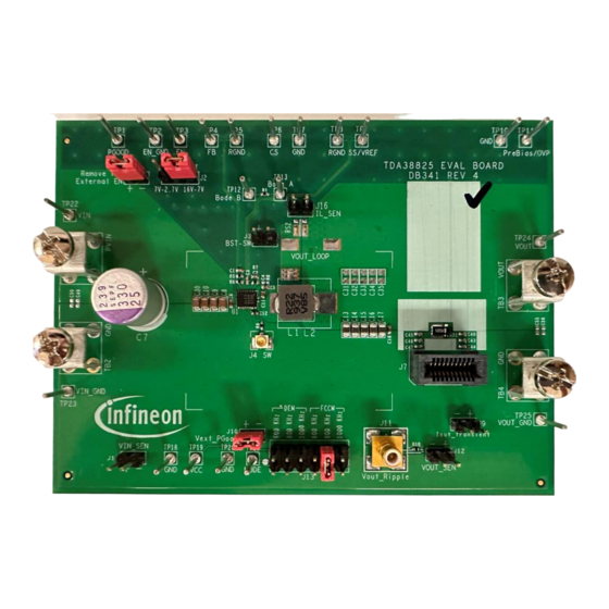
Page 6: Board Information
EVAL_TDA38825_1VOUT user guide User guide for TDA38825 evaluation board Board information Board information Evaluation board Figure 1 Evaluation board Board features = +12 V, V = +1 V at 0 to 20 A = 600 kHz/800 kHz/1000 kHz L = 220 nH = 10 x 22 µF (25 V, ceramic 0805) + 1 x 2.2 µF (25 V, ceramic 0805) + 1 x 330 µF (25 V, electrolytic, optional) = 10 x 47 µF (6.3 V, ceramic 0805) + 1 x 2.2 µF (6.3 V, ceramic 0805) -
Page 7: Connections And Operating Instructions
EVAL_TDA38825_1VOUT user guide User guide for TDA38825 evaluation board Board information Connections and operating instructions The TDA38825 demo board requires a single +12 V for the input power and can deliver up to 20 A load current. The operation modes and OCP limits can be selected through jumpers. Table 2 Connections Label... -
Page 8: Pcb Layout
EVAL_TDA38825_1VOUT user guide User guide for TDA38825 evaluation board Board information PCB Layout Figure 2 Top layer Figure 3 Bottom layer User Guide V 1.0 2023-07-21... - Page 9 EVAL_TDA38825_1VOUT user guide User guide for TDA38825 evaluation board Board information Figure 4 Inner layer 1 Figure 5 Inner layer 2 User Guide V 1.0 2023-07-21...
- Page 10 EVAL_TDA38825_1VOUT user guide User guide for TDA38825 evaluation board Board information Figure 6 Inner layer 3 Figure 7 Inner layer 4 User Guide V 1.0 2023-07-21...
-
Page 11: Schematic
EVAL_TDA38825_1VOUT user guide User guide for TDA38825 evaluation board Board information Schematic Figure 8 Schematic of the TDA38825 evaluation board V = 12 V, V = 1 V, I = 20 A OUTmax User Guide V 1.0 2023-07-21... -
Page 12: Bill Of Materials
EVAL_TDA38825_1VOUT user guide User guide for TDA38825 evaluation board Board information Bill of materials Table 3 Bill of materials Item Part Value Description Manufacturer Part number reference Ceramic capacitor 220 pF C1005X7R1H TDK Corporation 50 V X7R 0402 10% 221K050BA 2.2 µF Ceramic capacitor 2.2 µF TDK Corporation C1005X5R1C... - Page 13 EVAL_TDA38825_1VOUT user guide User guide for TDA38825 evaluation board Board information Vertical header connector – 12-position 2.54 mm Adam Tech PH2-12-UA Header connector R/A 3- – position 2.54 mm Harwin Inc. M20-9960345 UMCC straight jack TE Connectivity/ – connector 50 Ω SMD AMP Connectors 1909763-1 Dual female edge...
- Page 14 Vector Electronics K30C/M TP3, TP4, 1000/PKG TP5, TP6, TP7, TP8, TP9, TP10, TP11, TP12, TP13, TP18, TP19, TP20, TP21, TP22, TP23, TP24, TP25 TDA3 TDA38825 20 A single- Infineon TDA38825 voltage synchronous buck 8825 regulator User Guide V 1.0 2023-07-21...
-
Page 15: Evaluation Board Test Results
EVAL_TDA38825_1VOUT user guide User guide for TDA38825 evaluation board Evaluation board test results Evaluation board test results Typical efficiency and power loss curves = 12 V, F = 800 kHz, Mode: DEM and FCCM = 0 A – 20 A, F = 12 V, V = internal LDO, I = 800 kHz, room temperature, natural convection. - Page 16 EVAL_TDA38825_1VOUT user guide User guide for TDA38825 evaluation board Evaluation board test results = 12 V, F = 800 kHz - internal LDO, natural convection, T = 25°C 0.6V - DEM 0.6V - FCCM 1.0V - DEM 1.0V - FCCM 1.8V - DEM 1.8V - FCCM 3.3V - DEM...
-
Page 17: Typical Operating Waveforms
EVAL_TDA38825_1VOUT user guide User guide for TDA38825 evaluation board Evaluation board test results regulation 1.0005 0.9995 0.999 0.9985 0.998 0.9975 0.997 Output current (A) Figure 10 Output voltage regulation Typical operating waveforms = 12.0 V, V = 1 V, I = 20 A, F = 800 kHz, room temperature, no airflow Figure 11... - Page 18 EVAL_TDA38825_1VOUT user guide User guide for TDA38825 evaluation board Evaluation board test results Figure 12 Pre-bias start-up at 0 A load, (Ch1: V , Ch2: V , Ch3: P , Ch4: enable) GOOD Figure 13 ripple at 20 A Load, F = 800 kHz, (Ch2: V User Guide V 1.0...
- Page 19 EVAL_TDA38825_1VOUT user guide User guide for TDA38825 evaluation board Evaluation board test results Figure 14 SW node jitter, 20 A load, F = 800 kHz Figure 15 SW node (in DEM), 1 A load User Guide V 1.0 2023-07-21...
- Page 20 EVAL_TDA38825_1VOUT user guide User guide for TDA38825 evaluation board Evaluation board test results Figure 16 Short-circuit and UVP (Hiccup), (Ch2: V , Ch3: P GOOD = 5A – 15 A, Figure 17 Transient response at 10 A step load current at 10 A/µs slew rate: I (Ch6: V , Ch2: I , Ch4: Sw), pk-pk: 55 mV, F...
- Page 21 EVAL_TDA38825_1VOUT user guide User guide for TDA38825 evaluation board Evaluation board test results Switching frequency vs. load current 1200 1000 Max.Fsw_12Vin_800kHz Max.Fsw_12Vin_1000kHz Max.Fsw_12Vin_600kHz Figure 18 Switching frequency vs. load current Switching frequency vs. input voltage = 10 A 1200 1000 Input Voltage Frequency_600KHz Frequency_800KHz...
- Page 22 EVAL_TDA38825_1VOUT user guide User guide for TDA38825 evaluation board Evaluation board test results Switching frequency vs. output voltage = 20 A 1200 1000 Output voltage Frequency_600KHz Frequency_800KHz Frequency_1000KHz Figure 20 Switching frequency vs. output voltage User Guide V 1.0 2023-07-21...
-
Page 23: Thermal Images With No Air Flow And 25°C Ambient
EVAL_TDA38825_1VOUT user guide User guide for TDA38825 evaluation board Evaluation board test results Thermal images with no air flow and 25°C ambient • Output voltage - 1 V • SP1- TDA38825 • SP2-PCB • SP3- Inductor • Output voltage - 3.3 V •... -
Page 24: Revision History
EVAL_TDA38825_1VOUT user guide User guide for TDA38825 evaluation board Revision history Revision history Document Date of release Description of changes version V 1.0 2023-07-21 Initial release User Guide V 1.0 2023-07-21... - Page 25 Infineon Technologies office. 81726 Munich, Germany Except as otherwise explicitly approved by Infineon Technologies in a written document © 2023 Infineon Technologies AG. signed by authorized representatives of Infineon All Rights Reserved.
Need help?
Do you have a question about the EVAL TDA38825 1VOUT and is the answer not in the manual?
Questions and answers