
Related Manuals for Baroness LM551B


Summary of Contents for Baroness LM551B
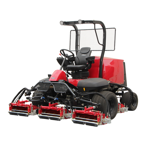
- Page 1 5-Unit Reel Mower Owner's Operating Manual Serial No. LM551B:30394- "Required reading" Read this manual before using the machine. Original Instructions Ver.2.0...
- Page 2 LM551B Regulations California Proposition 65 EU Regulations (For California, USA) (For EU) This product complies with all relevant EU Regulations. WARNING: For more information, please refer to the Operating, servicing and maintaining Declaration of Conformity attached. a passenger vehicle or off-road EU Emission Control (StageⅤ)
- Page 3 LM551B Greeting Thank you for purchasing the Baroness product. QR Code This manual describes the proper handling, adjustment, and inspection of your product. A QR code label is affixed on the machine. We hope you will use the product safely, and take advantage of its best performance.
- Page 4 The operator is responsible for operating the product properly and safely. Maintenance service for this machine should be performed by a mechanic with expertise. If you have any questions concerning maintenance or genuine parts, please contact a Baroness dealer or Kyoeisha.
- Page 5 When replacing parts, be sure to use genuine Baroness parts or parts designated by Kyoeisha. Note that the Baroness product warranty may not apply to defects caused by the use of parts from other companies. Prior to use, carefully read the following manuals to thoroughly understand the contents for safe and correct operation.
- Page 6 LM551B Introduction...
-
Page 7: Table Of Contents
LM551B Contents Safety .............. Page 1-1 Maintenance ........... Page 6-1 Safe Operating Practices .......Page 1-2 Precautions for Maintenance ......Page 6-2 Jacking Up The Machine ....... Page 6-2 Disposal ............Page 2-1 Greasing ............Page 6-4 Recycle and Waste Disposal ......Page 2-2 Lubrication ............. - Page 8 LM551B Contents...
-
Page 9: Safety
LM551B Safety Safe Operating Practices ...... Page 1-2 Training ..........Page 1-2 Preparation ..........Page 1-2 Operation ..........Page 1-3 Maintenance .......... Page 1-4 Storage ..........Page 1-5 Page 1-1... -
Page 10: Safe Operating Practices
LM551B Safety Failure to adequately follow these safety Never allow children or people unfamiliar precautions may cause an accident resulting in with these instructions to use or service the injury or death. machine. Local regulations may restrict the age of the Danger operator. -
Page 11: Operation
LM551B Safety Add fuel before starting the engine. Never operate while people, especially Never remove the cap of the fuel tank or children, or pets are nearby. add fuel while the engine is running or Only operate in good light, keeping away when the engine is hot. -
Page 12: Maintenance
LM551B Safety Before removing the grass catcher. Allow the engine/muffler to cool before checking/maintenance. Before making height or depth adjustment unless adjustment can be made from the To reduce the fire hazard, keep hot parts operator's position. such as the engine and silencer/muffler, battery compartment and fuel storage area Before clearing blockages. -
Page 13: Storage
LM551B Safety When checking the hydraulic circuit for Swallowing engine coolant can cause injury pinhole leaks or oil leakage from nozzles, do or death; keep out of reach from children and not use your hands. pets. Use items such as paper or corrugated cardboard to find leakage points. - Page 14 LM551B Safety Page 1-6 Safe Operating Practices...
-
Page 15: Disposal
LM551B Disposal Recycle and Waste Disposal ....Page 2-2 About Recycle ........Page 2-2 About Waste Disposal ......Page 2-2 Page 2-1... -
Page 16: Recycle And Waste Disposal
LM551B Disposal Recycle and Waste Disposal About Recycle Recycling battery etc. is recommended for environmental conservation and economical use of resources. It may be required by local laws. About Waste Disposal Make sure that waste generated when servicing or repairing the machine is disposed of in accordance with local regulations. -
Page 17: Product Overview
LM551B Product Overview Specifications ........Page 3-2 Specifications .........Page 3-2 Mower Units ...........Page 3-4 Sound Pressure Level ......Page 3-4 Sound Power Level ....... Page 3-4 Vibration Level ........Page 3-4 Carbon Dioxide (CO2) Emissions ..Page 3-4 Names of Each Section ......Page 3-5 Regulation Decals ........Page 3-5... -
Page 18: Specifications
LM551B Product Overview Specifications Specifications Model LM551B Name 5-Unit Reel Mower Mower unit type 22 in 26 in Total length 295 cm 116.14 in ← ← During operation 292 cm 114.96 in LH52 During transport 220 cm 86.61 in During operation 294 cm 115.75 in... - Page 19 LM551B Product Overview 1498 cm Total displacement 91.41 cu.in. ← ← (1.498 L) Engine Maximum output ← Rated output 33.0 kW (44.9 PS)/3000 rpm ← Diesel 51.0 Diesel 13.47 Fuel tank capacity ← ← U.S.gals (51.0 L) 262 g/kW・h 192 g/PS・h Fuel consumption ←...
-
Page 20: Mower Units
LM551B Product Overview Mower Units Baroness mower unit that can fit this machine is the model marked with a circle in the "Attachable unit" column. LM551/LM551B Attachable Model Remarks unit LH52 22 in 〇 LH62 22 in 〇 ... -
Page 21: Names Of Each Section
LM551B Product Overview Names of Each Section Regulation Decals Positions of Regulation Decals B,C,D I,J,K 685A572B Positions of Regulation Decals_001 Serial number plate 10,11 Specification decal CE Mark UKCA mark (#30093 – 30352) Noise emission decal Year of manufacture decal... - Page 22 LM551B Product Overview Specification Decal Noise Emission Decal (For EU) (For EU) The Specification decal indicates the model The noise emission decal indicates the sound and weight, etc. power level determined by measuring identical machines in accordance with the procedure specified in the regulations of EU or UK.
- Page 23 LM551B Product Overview ROPS Compliance Decal Recycle Decal The ROPS compliance decal indicates the Recycle Decal illustrates Recycle Mark in manufacturer, model, etc., in accordance with accordance with local regulation. International Standard ISO 21299:2009. (For EU) c3td3e-003 y7wov5-001 ROPS Compliance Decal_001...
- Page 24 LM551B Product Overview California Proposition 65 Decal (Riding Type) (For the State of California, USA) California Proposition 65 decal describes the warning messages as required by California Proposition 65. WARNING: Operating, servicing and maintaining a passenger vehicle or off-road vehicle can expose you to chemicals including...
-
Page 25: Safety Signs And Instruction Signs
6iul4h-209 Positions of Safety Decals and Instruction Decals_002 Part numbers for decals that need to be replaced are listed in the parts catalog. Order them from a Baroness dealer or Kyoeisha. Positions of Safety Decals and Instruction Decals 6iul4h-135... - Page 26 LM551B Product Overview 6iul4h-138 Positions of Safety Decals and Instruction Decals_006 Decal for operation 2 Caution to rotating object decal Caution to hot parts decal Caution to injury decal Caution for mower lock decal Caution to getting pinched decal Fire prohibited decal...
-
Page 27: Description Of Safety Decals And Instruction Decals
LM551B Product Overview Description of Safety Decals and Instruction Decals Caution Rollover - Do not work on slopes of 15 Decal for Operation (E5) degrees or more. STICKER, OPERATION (E5) When you descend a slope, lower the mower LM551B-0604Z0 units and then drive at low speed. - Page 28 LM551B Product Overview Caution to Hot Parts Decal Caution for Mower Lock Decal K4205001540 K4205001900 Decal for caution to hot parts Decal, caution for mower lock Lock the mower units when traveling or Caution storing with the mower units #4 and 5 raised.
- Page 29 LM551B Product Overview Fire Prohibited Decal PTO Caution Decal K4205001940 K4205002000 Decal, fire prohibited Decal, caution PTO Warning Warning Keep away from fire. Watch for rotating parts - Keep your hands away from the joints while the engine is running.
- Page 30 LM551B Product Overview Diesel Fuel Icon DPF Regeneration Lamp Mark K4209001000 DPF regeneration lamp mark Diesel fuel icon Seek monitor information when the green Use diesel fuel. lamp lighting or blinking. xmitt2-001 alqcju-005 Diesel Fuel Icon_001 DPF Regeneration Lamp Mark_001...
-
Page 31: Operation Decals
LM551B Product Overview Operation Decals Positions of Operation Decals 6n6oux-154 Positions of Operation Decals_005 6n6oux-201 Positions of Operation Decals_001 6n6oux-202 Positions of Operation Decals_006 Key switch decal Engine rotation mark 6n6oux-151 Light switch mark Positions of Operation Decals_002 Reel rotation switch mark... -
Page 32: Description Of Operation Decals
LM551B Product Overview Description of Operation Decals Light Switch Mark Key Switch Decal Note: Depending on the specifications, this function Decal, key switch may not be available. This indicates the key switch positions. Light switch mark It illustrates ON/OFF of the light. - Page 33 LM551B Product Overview Mower Unit Up/Down Decal Tilt Steering Decal Decal, mower unit up/down K4203001710 This indicates the Up/Down positions of the Decal, tilt steering mower unit. This illustrates the tilt directions of the steering wheel and the locked/free positions.
- Page 34 LM551B Product Overview BRAKE Decal BACKWARD Decal K4203001450 K4203001440 Decal, BRAKE Decal, BACKWARD This indicates brake. This indicates backward travel. BRAKE BACKWARD 7elqr2-001 kqca3e-002 BRAKE Decal_001 BACKWARD Decal_001 FORWARD Decal Driving Mode Shift Decal K4203001430 K4203001740 Decal, FORWARD Decal, shifting driving mode This indicates forward travel.
- Page 35 LM551B Product Overview Lever Open/Close Decal Reel Rotation Decal K4203001720 K4203001300 Decal, open/close lever Decal, reel rotation This indicates lock/release of open/close This indicates rotation of the reel cutter lever. (cutting cylinder). u6xhxw-001 if834g-001 Lever Open/Close Decal_001 Reel Rotation Decal_001...
- Page 36 LM551B Product Overview DPF Switch Decal LM551--0586Z0 Decal, DPF Switch This indicates the changeover of DPF regeneration. z1lbi4-005 DPF Switch Decal_001 Page 3-20 Operation Decals...
-
Page 37: Description Of Functions
LM551B Description of Functions Proximity Sensor ........Page 4-2 Engine ...........Page 4-40 Relays ............. Page 4-2 Handling Emission Control Compliant Engine ........ Page 4-40 Light Switch ........... Page 4-3 DPF ............Page 4-40 Traveling/Working Selector Switch ..Page 4-3 Reel Rotation Switch ......Page 4-4 Reel Forward/Reverse Switch .... -
Page 38: Proximity Sensor
LM551B Description of Functions Proximity Sensor Relays There are four proximity sensors on #1, #2, #4 The relay box is located inside the underseat and #5 mower arm fulcrums. cover. These sensors detect the raised or lowered These relays control traveling/working selection, positions of mower units #1, #2, #4 and #5. -
Page 39: Light Switch
LM551B Description of Functions Light Switch Note: Depending on the specifications, this function may not be available. Caution The lights provide auxiliary lighting. Do not travel or operate the machine at night or under poor visibility. ufahas-009 The light switch is located in the operation Traveling/Working Selector Switch_001 panel. -
Page 40: Reel Rotation Switch
LM551B Description of Functions Reel Rotation Switch Important If the reel rotation switch is not set to the Caution "Rotation" position, the reel cutter (cutting cylinder) will not rotate. Set the reel rotation switch to the "Rotation" position immediately before starting cutting The reel forward/reverse switch is located inside work. -
Page 41: Reel Rotation/Stop Switching Lever
LM551B Description of Functions Reel Rotation/Stop Switching Lever Mower Unit Up/Down Lever Caution Caution Before operating the reel rotation/stop Before raising or lowering the mower units, switching lever, be sure to set the reel rotation make sure that there are no people around switch to the "Stop"... -
Page 42: Throttle Knob
LM551B Description of Functions Note: Important When the mower units are raised, the reel cutters (cutting cylinders) stop rotating even if "Auto regeneration inhibit mode" inhibits all the reel rotation switch is set to the "Rotation" DPF regenerations of "Auto regeneration", position. -
Page 43: Dpf Parked Regeneration Switch
LM551B Description of Functions When the DPF auto regeneration inhibit switch DPF parked regeneration switch is pressed and set to "Auto regeneration inhibit mode", the monitor displays DPF auto When DPF parked regeneration starts, DPF regeneration inhibit icon. regeneration icon in the monitor display changes from blinking to lighting. -
Page 44: Pedal Stopper
LM551B Description of Functions yo3h9x-012 Traveling Pedal_002 Traveling pedal (forward) Traveling pedal (backward) Bolt Spring washer unp7tf-005 Pedal Stopper Pedal Stopper_001 Pedal stopper Important Operating speed lock lever When the traveling speed exceeds 12.0 km/h Traveling pedal during cutting operation, a buzzer will sound. -
Page 45: Brake Pedal
LM551B Description of Functions Open the protective cover. Brake Pedal Caution When leaving the driver's seat, park the machine on a stable, flat surface and be sure to apply the parking brake. Caution Never park the machine on a slope. -
Page 46: Open-Close Lever
LM551B Description of Functions 2.1 A Important Indicator When you restart the engine after the safety device stops the engine, be sure to return the Insert the device USB plug into the port. ignition key to the "OFF" position first, and The blue indicator lights when applying then restart it. -
Page 47: Dpf Regeneration Lamp
LM551B Description of Functions Engine Overload Warning Buzzer Engine warning lamp (LED) lights up or blinks If the traveling pedal is depressed and the when a failure occurs on the function of engine. speed exceeds 12.0 km/h while the pedal Check the fault code (DTC) in the monitor stopper is in the "Traveling"... -
Page 48: Monitor (Pv380)
LM551B Description of Functions Engine warning lamp blinks when only DTC LED (red) relevant to PCD/NCD come up. Lights up when a critical malfunction on the engine is detected. vdod12-003 Engine Warning Lamp_003 C77ADD47 Monitor LED_001 Fault detected LED (yellow) -
Page 49: Opening Screen
LM551B Description of Functions LED (yellow) Lights up when a malfunction is detected, indicating warning and/or caution on the engine and also lights up when SERVICE REMINDERS or DPF CLEANING ALARM advised. LED (red) Lights up when a critical malfunction on the engine is detected. -
Page 50: Gauge Screen
LM551B Description of Functions Note: While preheating, the message "Wait to Start...Preheating" is displayed. When the preheat completed, "Wait to Start...Preheating" disappears and GAUGE screen appears. ENGINE SPEED HOUR METER COOLANT TEMP FUEL LEVEL ENGINE SPEED HOUR METER Wait to Start... Preheating... - Page 51 LM551B Description of Functions The first page (displayed when the monitor The third page activated) DPF ACTIVE REGEN DOC TEMP INACTIVE ENGINE SPEED HOUR METER DPF INTAKE TEMP DPF OUTLET TEMP COOLANT TEMP FUEL LEVEL 8C29AC98 83ABD857 Gauge Screen_004 Gauge Screen_002 The second page %...
-
Page 52: Menu Screen
LM551B Description of Functions The fourth page Note: If "Button 5" is pressed on the fourth page, the first page appears in the screen. kg/h MENU USER SETTINGS SERVICE REMINDERS STORED FAULT CODES VERSION INFORMATION SYSTEM MENU DPF DIFF PRES... - Page 53 LM551B Description of Functions Press the button 3 to move to MENU screen and save the setting. If you turn the ignition key to the "OFF" position before moving to MENU screen, the setting will not be saved. Metric kPa 日本語...
- Page 54 LM551B Description of Functions Press the button 3 to move to MENU Italian ・ screen and save the setting. Portuguese ・ If you turn the ignition key to the "OFF" Dutch ・ position before moving to MENU screen, Press the button 3 to move to MENU the setting will not be saved.
- Page 55 LM551B Description of Functions Units Button 3 Item Metric Metric Button 4 US STD Button 5 ENGINE SPEED Service Reminders HOUR METER "SERVICE REMINDERS" functions to notify COOLANT TEMP the operator of the appropriate timing of FUEL LEVEL service for the following items.
- Page 56 LM551B Description of Functions Service Machine Engine oil Engine oil filter Hydraulic oil Hydraulic oil filter Air cleaner interval Initial LM551B Periodic Initial GM281 Periodic Initial LM3210 Periodic Initial LM2710 Periodic Initial FS1710 Periodic Initial HM5500 Periodic The hours calculated based on the expiry of...
- Page 57 LM551B Description of Functions Service Reminders Reset ■ With "SERVICE REMINDERS", the displayed hours can be reset. Important The number in the service reminders can not be reset while the engine is running. Switch on the machine (set the ignition key to the "ON"...
- Page 58 LM551B Description of Functions The message "Reset complete" appears Press the button 3 to move to MENU when the setting saved. screen. Note: Once the displayed number reset, it appears as calculated based on the "periodical service interval hours". SERVICE REMINDERS...
- Page 59 LM551B Description of Functions Press the button 5 to move to SERVICE Press the button 5 to determine the setup REMINDERS SETTING screen. hours. 50.0 400.0 450.0 400.0 SERVICE REMINDERS SERVICE REMINDERS SETTING ENGINE OIL ENGINE OIL ENGINE OIL FILTER...
- Page 60 LM551B Description of Functions The interval hours after configuration saved appear in SERVICE REMINDERS SETTING screen. Press the button 3 to move to SERVICE REMINDERS screen. 50.0 400.0 450.0 400.0 50.0 400.0 450.0 400.0 SERVICE REMINDERS SETTING ENGINE OIL HOUR METER INTERVAL 50.0...
- Page 61 LM551B Description of Functions Press the button 3 to move to MENU Press the button 5 to move to SERVICE screen. REMINDERS SETTING screen. SERVICE REMINDERS SERVICE REMINDERS ENGINE OIL ENGINE OIL ENGINE OIL FILTER ENGINE OIL FILTER HYDRAULIC OIL...
- Page 62 LM551B Description of Functions Press the button 4 to delete the settings. 50.0 400.0 50.0 400.0 450.0 400.0 - - - SERVICE REMINDERS SETTING SERVICE REMINDERS ENGINE OIL SETTING HOUR METER INTERVAL ENGINE OIL 50.0 400.0 Locked while the Engine is running HOUR METER INTERVAL...
- Page 63 LM551B Description of Functions The interval hour "0.0" appears after Press the button 3 to move to MENU deletion complete in SERVICE screen. REMINDERS SETTING screen. Press the button 3 to move to SERVICE REMINDERS screen. 50.0 - - -...
- Page 64 LM551B Description of Functions The monitor receives the stored fault codes Stored Fault Codes while "RECEIVING" message appears. With "STORED FAULT CODES", the past fault codes can be checked. Once "STORED FAULT CODES" is SPN: 0 FMI: 0 selected, the monitor automatically requests the engine ECU to send the stored fault codes while "REQUESTING"...
- Page 65 LM551B Description of Functions The stored fault codes appear after the In case of plural stored fault code reception completed. The arrows of "↓" and "↑" appear in the Note: bottom of the monitor display. Press "Button 5" if you would like to receive Press "Button 1"...
- Page 66 LM551B Description of Functions In case of no stored fault code Installed "CONFIGURATION TITLE" "NO STORED FAULT CODES" appears. "Button 3": Move to the MENU screen. ・ SPN: 0 FMI: 0 ******* ***** STORED FAULT CODES VERSION INFORMATION SPN: 0 FMI: 0...
- Page 67 LM551B Description of Functions Refuel icon Descriptions of Displayed Icons The icon appears and blinks when the remaining fuel decreases to less than 10 The following icons appear in the GAUGE screen. Cleaning index icon The icon appears when the cleaning index is 50 %, 75 % or 100 %.
- Page 68 LM551B Description of Functions Slow blinking (Repeat of lighting up and DPF regeneration icon ・ down every 2 sec): The engine may be The DPF regeneration icon appears with stopped in the end due to decreasing DPF regeneration request or during DPF power output, etc.
- Page 69 LM551B Description of Functions Descriptions of Pop-up Messages These pop-up messages appear in the monitor display. SPN: 110 FMI: 3 P0118 High ・ FAULT CODES SERVICE REMINDERS ・ DPF CLEANING ALARM ・ Fault Codes Important When the fault code (DTC) appears in the monitor display, contact your dealer.
- Page 70 LM551B Description of Functions SPN: 110 FMI: 3 P0118 High ・ 再生禁止 FAULT CODES FAULT CODES SPN: 110 FMI: 3 P0118 Coolant temperature sensor : CAN BUS FAILURE(ENGINE ECU NO High COMMUNICATION) ・ Regeneration inhibited 3BDCD26B 42059C59 Fault Codes_002 Fault Codes_003...
- Page 71 LM551B Description of Functions When the fault code (DTC) appears, move When the setup time in SERVICE to GAUGE screen with pressing "Button 3". REMINDERS has elapsed, the pop-up Warning icons appear in the GAUGE message appears in the monitor display screen.
- Page 72 LM551B Description of Functions When five items should be advised for The second page ・ example, they appears in two pages. In that case, the arrows "←" and "→" appear in the bottom of the monitor display. You can move to another page with pressing "Button 1"...
- Page 73 LM551B Description of Functions Move to GAUGE screen with pressing When the prescribed time of Ash Timer has "Button 3" when the message displayed. elapsed, the pop-up message appears in The service icon appears in GAUGE the monitor display and the yellow LED screen.
- Page 74 LM551B Description of Functions When the prescribed time of Ash Timer Cleaning index 75 % ・ has not elapsed yet and the cleaning index is 50 % or more Cleaning index 50 % ・ 75 50 DPF CLEANING ALARM CLEANING INDEX 75 ...
- Page 75 LM551B Description of Functions Cleaning index 100 % Move to GAUGE screen with pressing ・ "Button 3" when the message displayed. The cleaning index icon appears in GAUGE screen. 100 DPF CLEANING ALARM CLEANING INDEX 100 CLEANING INDEX is now 100%...
-
Page 76: Engine
Interrupting the regeneration or ignoring the LM3210 ○ ○ ○ warning may cause the engine and DPF to malfunction. LM551A ○ ○ LM551B ○ ○ ○ GM2810 ○ Important ○ ○ GM2810 Do not repeat unnecessary DPF regeneration ○... - Page 77 LM551B Description of Functions The engine rotation speed is minimum ・ DPF Regeneration and Replacement or idling speed. The DPF is a purifying filter that collects PM The coolant temperature is 65 °C or ・ (soot) from exhaust gas. more.
- Page 78 LM551B Description of Functions PM Accumulation Level ■ The following table shows the regeneration method and the machine status in each PM accumulation level. PM accumulation DPF regeneration Displayed fault code Monitor LED Engine output limit level method Level 0...
- Page 79 LM551B Description of Functions In "Auto regeneration inhibit mode" or "Parked regeneration" is the DPF when DPF auto regeneration inhibit icon regeneration forcibly performed, parking this appears machine in a safe location, when auto regeneration does not reduce the amount of When PM accumulation level enters accumulated PM to the specified value.
- Page 80 LM551B Description of Functions In "PM accumulation Level 1" or "Level 2": Park this machine in a safe location immediately. Important Apply the parking brake. If DPF regeneration remains uncompleted in Set the engine to minimum rotation auto regeneration, parked regeneration is speed or idling speed.
- Page 81 LM551B Description of Functions "Excessive PM3" appears in the monitor The expert performs "DPF Manual display. regeneration" with the fault diagnostic tool when normal auto regeneration or parked regeneration can not complete regeneration since large amount of PM accumulates. DPF manual regeneration is activated when...
- Page 82 LM551B Description of Functions "Excessive PM4" appears in the monitor Follow these procedures to request DPF display. replacement. When cleaning index of "DPF Cleaning Alarm" reaches to 100 %: Contact your dealer for DPF replacement. SPN: 3701 FMI:16 In PM accumulation "Level 5": P3007 PM The engine output is limited at 50 %.
- Page 83 LM551B Description of Functions "High frequency of regeneration" appears in the monitor display. SPN: 523602 FMI: 0 P3024 FAULT CODES SPN: 523602 FMI: 0 P3024 High frequency of regeneration Output limitation DFD4F65E Replacement of DPF_002 LED (yellow) Park this machine in a safe location immediately.
- Page 84 LM551B Description of Functions Relationship between PM Accumulation Level and DPF Regeneration Important In "Auto regeneration inhibit mode", any DPF regeneration of "Auto", "Parked" and "Manual" is prohibited. Cancel "Auto regeneration inhibit mode" to perform DPF regeneration. In "Auto regeneration mode" or when DPF auto regeneration inhibit icon disappears:...
-
Page 85: Handling Instructions
LM551B Handling Instructions Operations Before Service ....Page 5-2 Leaving the machine ......Page 5-21 Move ............Page 5-22 Opening and Closing of Radiator Cover ............. Page 5-2 Traveling Procedure ......Page 5-22 Opening and Closing of Hood ....Page 5-2 Cutting Work ........Page 5-22 Opening and Closing of Underseat Cover ............. -
Page 86: Operations Before Service
LM551B Handling Instructions Remove the nuts and bolts locking the catch Operations Before Service clips on the left and right sides of the hood. The following sections describe the preparatory works required before performing the services including inspection, adjustment, cleaning. -
Page 87: Opening And Closing Of Underseat Cover
LM551B Handling Instructions Lift up the hood. While unlocking with the open-close lever, grab the grip and tilt the seat to the right to open the underseat cover. i5jb7e-031 Opening and Closing of Hood_003 ljffir-017 Hood Opening and Closing of Underseat Cover_002 Close the hood slowly. -
Page 88: Inspection And Cleaning
LM551B Handling Instructions Radiator Inspection and Cleaning Inspection of Radiator Inspect and clean the machine with the goals of the followings. Make sure that there is no damage to the Accident prevention ・ radiator. Failure prevention ・ Make sure that the radiator is not Performance retention ・... -
Page 89: Coolant
LM551B Handling Instructions Pull up the radiator cover to remove it. Carefully clean the radiator with water or compressed air. Coolant Inspection of Coolant Caution Do not touch the radiator or coolant during engine operation or immediately after the engine has been turned off. -
Page 90: Oil Cooler
LM551B Handling Instructions Coolant Supply Reserve tank Reserve tank cap Caution If no coolant is in the reserve tank, follow Do not touch the radiator or coolant during the steps below to supply clean water. engine operation or immediately after the Open the radiator cap, and then supply engine has been turned off. -
Page 91: Hydraulic Oil
LM551B Handling Instructions Make sure that the oil level is at the middle Cleaning of Oil Cooler of the oil gauge. Important An unclean oil cooler may cause malfunction of the hydraulic system. Important Do not use solid objects, such as a spatula or screwdriver, or high-pressure water to clean the radiator or oil cooler. - Page 92 LM551B Handling Instructions If the hydraulic oil level is low, follow the Supply of Hydraulic Oil steps below to supply oil. Open the tank cap, and then supply Important hydraulic oil through the oil filling port Do not mix different types of oil.
-
Page 93: Hydraulic Hoses
LM551B Handling Instructions Hydraulic Hoses Air cleaner Indicator Inspection of Hydraulic Hoses and Pipes Make sure that there is no damage to the air cleaner. Warning Make sure that the air cleaner element is When checking the hydraulic circuit for not contaminated. -
Page 94: Battery
LM551B Handling Instructions Reset button Important Indicator The inner element cannot be cleaned. Battery Follow the steps below to clean the outer Inspection of Battery element. Remove the clips from the three locations, remove the air cleaner cap, Danger and then remove the outer element. - Page 95 LM551B Handling Instructions Inspecting the mounting bracket Inspect whether the battery is secured firmly with the mounting bracket. If the bracket is loose, tighten the mounting U P P E R L E V E L bracket nuts until the battery is secured L O W E R L E V E L firmly.
-
Page 96: Electrical Wiring
LM551B Handling Instructions Supply of Battery Fluid Danger U P P E R L E V E L L O W E R L E V E L Since the battery fluid is dilute sulfuric acid, be careful not to let your skin, clothes or vehicle, etc. -
Page 97: Brake
LM551B Handling Instructions Brake Safety Device Inspection of Brake Pedal Inspection of Interlock System Make sure that there is no play in the pedal. Make sure that the interlock system operates correctly. Make sure that the pedal moves smoothly. (Refer to "Interlock System") -
Page 98: Engine Oil
LM551B Handling Instructions Engine Oil Supply of Engine Oil Inspection of Engine Oil Important Do not supply too much engine oil. Otherwise, Important the engine may be damaged. Securely tighten the oil level gauge and oil filler cap. Important Check the oil level 10 to 20 minutes after Do not mix different types of engine oil. -
Page 99: Fuel
LM551B Handling Instructions Fuel Important In case of lack of fuel, DPF regeneration can Inspection of Fuel not be performed. With the machine on a level surface, check “FUEL LEVEL” in the monitor. If the monitor displays "Supply fuel icon" and If the fuel level is low, supply diesel fuel. -
Page 100: Water Separator
LM551B Handling Instructions Water Separator Air Bleeding of Fuel System Inspection of Water Separator Important The air-bleed plug should always be in the Important closed position except during the air bleeding If water contaminates the fuel, the supply operation. pump and injector will seize due to heat. -
Page 101: Fuel Filter
LM551B Handling Instructions Clean the water separator in accordance with Draining of Water Separator the Maintenance Schedule. However, when debris has accumulated in the Important cup, clean it even before the schedule. If water contaminates the fuel, the supply Follow the steps below to clean the water pump and injector will seize due to heat. -
Page 102: Liquid Leakage
LM551B Handling Instructions Check the wheel mounting bolts and wheel Liquid Leakage nuts for cracks and damages. Inspection of Liquid Leakage Check the wheel mounting bolts and wheel nuts for rust. Check around the wheel mounting bolts Important and wheel nuts for traces of rust fluid. -
Page 103: Adjustment Before Work
LM551B Handling Instructions Adjustment before Work Tilt lever FREE (released) Adjustment of Steering Wheel Position LOCK (locked) Adjustment of Seat Position Warning Do not make adjustments while traveling since Warning doing so is dangerous. Do not make an adjustment while traveling since it is dangerous. -
Page 104: Start/Stop Of Engine
"Down" position and the key switch is turned Make sure that the "BARONESS" logo or the to the "ON" position while the engine is logo and "Warming up" message appears in... -
Page 105: Parking And Stopping
Handling Instructions GAUGE screen appears in the monitor Procedure to Stop Engine display. Make sure that the "BARONESS" logo or the Danger logo and "Warming up" message disappeared in the monitor display, and the Since it will become extremely hot around the yellow and red LEDs are turned off. -
Page 106: Move
LM551B Handling Instructions Get out of the driver's seat. Cutting Work Move Cutting Work Traveling Procedure Caution Caution Be sure to operate at an appropriate speed for Under any circumstances drive the machine at the mowing site. a speed that you can stop it immediately for When cutting over bumpy surfaces, keep the emergencies. -
Page 107: Removal/Installation Of Grass Catcher
LM551B Handling Instructions Set the traveling/working selector switch to Removal/Installation of Grass Catcher the "Working" position. Shift the mower unit up/down lever to the Caution "Down" position to lower the mower units. Stop the engine before removing or installing Set the reel rotation switch to the "Rotation"... -
Page 108: Transporting
LM551B Handling Instructions Transporting Transporting Procedure When using a truck or trailer for transporting, drive the machine forward to load it and in reverse to unload it. If the roof is installed on the machine, remove Otherwise, the roof may be damaged by wind pressure. -
Page 109: Maintenance
LM551B Maintenance Precautions for Maintenance ....Page 6-2 Jacking Up The Machine .......Page 6-2 About Jacking Up The Machine .....Page 6-2 Jack-Up Points ........Page 6-2 Greasing ..........Page 6-4 About Greasing ........Page 6-4 Greasing Points ........Page 6-4 Lubrication ..........Page 6-8 About Lubrication ........Page 6-8... -
Page 110: Precautions For Maintenance
First, learn well the operations you plan to perform. Important Use tools appropriate for each operation. Important Use Baroness genuine parts for replacement and accessories. Our product warranty may be void if you use non-genuine parts for replacement or accessories. - Page 111 LM551B Maintenance Front right frame rwyt62-109 rwyt62-104 Jack-Up Points_005 Jack-Up Points_002 Pivot Front left frame Block of wood Left pivot rwyt62-105 Jack-Up Points_003 Right pivot rwyt62-108 Jack-Up Points_006 When jacking up the machine at the left pivot, place a block of wood between the left pivot and the frame.
-
Page 112: Greasing
LM551B Maintenance Greasing No. of Location greasing About Greasing points Mower arm fulcrum Since there may be adhesion or damage due Lift arm fulcrum to lack of grease on moving parts, they must be greased. Lift arm fulcrum shaft Add urea-based No. - Page 113 LM551B Maintenance Mower unit #3 Lift arm fulcrum There is one greasing point on each lift arm fulcrum (on the main vehicle side) connected to the mower unit. Mower units #1 and #4 8bq62b-361 Greasing Points_004 Mower unit #4 8bq62b-369...
- Page 114 LM551B Maintenance Mower unit #5 Mower unit #5 8bq62b-370 8bq62b-368 Greasing Points_010 Greasing Points_013 Lift arm fulcrum shaft Swiveling bracket fulcrum There is one greasing point on each lift arm There is one greasing point on each fulcrum shaft (on the mower arm side) swiveling bracket fulcrum connected to the connected to the mower unit.
- Page 115 LM551B Maintenance Brake pedal shaft fulcrum Rear wheel Left 8bq62b-373 8bq62b-377 Greasing Points_016 Greasing Points_020 Traveling pedal shaft fulcrum Rear wheel Right 8bq62b-374 8bq62b-378 Greasing Points_017 Greasing Points_021 Pedal stopper Joint 8bq62b-375 8bq62b-379 Greasing Points_018 Greasing Points_022 Pivot Rear wheel Middle...
-
Page 116: Lubrication
LM551B Maintenance Reel motor shaft Lubricating Points Apply 2 g (0.004 lb) of MORI SPEED GREASE NO.2 to the reel mower shaft Apply lubricant at the following locations every mounted on each mower unit every 250 50 hours of operation. - Page 117 LM551B Maintenance 9llqa9-018 9llqa9-022 Lubricating Points_003 Lubricating Points_007 Mower cylinder spherical bearing Mower unit #3 There are two locations on each mower cylinder. Mower unit #1 9llqa9-023 Lubricating Points_008 9llqa9-019 Lubricating Points_004 9llqa9-024 Lubricating Points_009 Mower unit #4 9llqa9-020 Lubricating Points_005...
-
Page 118: Operations Before Maintenance
LM551B Maintenance Important With the mower units LH66 installed, they can not swivel 90 degrees. 9llqa9-026 Lubricating Points_011 Mower unit #5 sibu71-016 Swiveling Mower Units #2 and #3_001 Mower unit swivel angle 90 ° Mower unit swivel angle 45 °... - Page 119 LM551B Maintenance Swivel the mower unit toward the outside of Mower unit position: Rear the main vehicle. Use the center locking hole (B) for maintenance. sibu71-011 Swiveling Mower Units #2 and #3_003 sibu71-013 Swiveling Mower Units #2 and #3_005 Mower unit...
-
Page 120: Adjustment And Replacement
LM551B Maintenance Adjustment and Replacement Replacement of Rear Tire Removing rear tires Replacement of Tires Follow the steps below to remove the rear Replacement of Front Tires tire. Loosen the bolts. Removing front tires Follow the steps below to remove the front tires: Loosen the bolts. -
Page 121: Adjustment Of Belt Tension
LM551B Maintenance Be sure to tighten bolt A, nut and bolt B Adjustment of Belt Tension securely after adjustment. Warning Be sure to stop the engine before adjusting the belts. Important For the specified value of belt tension, refer to Adjusted Values. -
Page 122: Adjustment Of Control Arm
LM551B Maintenance Control arm Spring washer Washer Bolt Adjustment of Reel Rotation Control Valves The reel rotation control valves adjust the F38DD52C rotation speeds of the reel cutters (cutting Adjustment of Fan Belt_002 cylinders). Adjust according to the operating conditions. - Page 123 LM551B Maintenance Use the specialized wrench (accessory) to Open the underseat cover. loosen the lock nut for the dial. Use the specialized wrench (accessory) to Note: loosen the lock nut for the dial. Raise the lock nut to a position where it will not interfere when the dial is turned.
-
Page 124: Adjustment Of Stoppers
LM551B Maintenance Turn the dial counterclockwise to set it to the Note: appropriate position. The stopper is not used when the mower units The amount that the dial is turned differs LS66/LH66 installed. depending on the mower unit. The stopper installation position for each For example, the following procedures show mower unit model is shown below. -
Page 125: Adjustment Of Mower Locking Pin
LM551B Maintenance To release: Adjustment of Mower Locking Pin Insert the cotter pin into the lower hole in the mower locking pin. The mower locking pin can prevent or allow tilting of the mower units. Adjust according to the operating conditions. -
Page 126: Adjustment Of Mower Stabilizer
LM551B Maintenance Adjustment of Mower Stabilizer Important When a grass catcher is installed on LH52, a Note: large movement range of the mower will Depending on the specifications, this function cause the grass catcher to come into contact may not be available. -
Page 127: Adjustment Of Mower Unit Leveling Spring
LM551B Maintenance Mower unit #3 Adjustment of Mower Unit Leveling Spring A coil spring is installed on the mower unit coupling. This keeps the mower unit level. Adjust the coil spring with the holes in the lift arm. Mower unit #1... -
Page 128: Adjustment Of Positions Of Mower Units #2 And #3
LM551B Maintenance Mower units #2 and #3 can be slid to the front Coil spring position or rear position. The slide distance is Lift arm 200 mm (7.87 in). Light spring load (standard position) On a level surface, lower all mower units. - Page 129 LM551B Maintenance In the same way, loosen bolt A and Slide mower units #2 and #3 from the remove bolts B of mower unit #2. front position to the rear position. Slide mower units #2 and #3 from the rear position to the front position.
-
Page 130: Adjustment Of Mower Stopper
LM551B Maintenance LH66・LH52・LS62・LS66 Adjustment of Mower Stopper Adjustment of Mower Stoppers for Mower Unit #1 The mower stopper is installed to prevent the mower unit from interfering with the frame. The attaching direction of the mower stopper for mower unit #1 differs according to the type of mower unit. - Page 131 LM551B Maintenance Mower unit #2 Adjustment of Mower Stoppers for Mower Unit #2 and #3 The mower stopper is installed to prevent the mower unit from interfering with the frame. The type and attaching direction of the mower stopper for mower unit #2 and #3 differ according to the type of mower unit.
- Page 132 LM551B Maintenance LH62 LH66 Mower unit #3 After installing the mower stoppers, press the stopper auxiliary fitting COMP firmly against the bottom side of the frame and secure it with the bolts. oxie9a-017 Adjustment of Mower Stoppers for Mower Unit #2 and...
- Page 133 LM551B Maintenance LS66 Adjustment of Mower Stoppers for Mower Unit #4 Mower unit #2 and #5 After installing the mower stoppers, press the stopper auxiliary fitting COMP firmly The mower stopper is installed to prevent the against the bottom side of the frame and mower unit from interfering with the frame.
-
Page 134: Adjustment Of #4 And 5 Hydraulic Hose Guides
LM551B Maintenance Attach the cotter pin and washer. Tighten the nuts on the U-shaped bracket to fix the hose guide. Fix the hose guide so that the hydraulic hose can go just above the hydraulic motor when seeing the mower unit from the motor side. - Page 135 LM551B Maintenance LH62・LH66 35AC3551 A097FA79 Adjustment of #4 and 5 Hydraulic Hose Guides_005 Adjustment of #4 and 5 Hydraulic Hose Guides_002 60 mm(2.36 in) 40 ° LH52 63E5DA39 B4B906FA Adjustment of #4 and 5 Hydraulic Hose Guides_003 Adjustment of #4 and 5 Hydraulic Hose Guides_006 50 mm(1.97 in)...
-
Page 136: Change Of Coolant
LM551B Maintenance Change of Coolant LLC concentration Freezing temperature (volume %) Down to -10 °C (14 °F) 20 % Caution Down to -15 °C (5 °F) 30 % Do not touch the radiator or coolant during Down to -20 °C (-4 °F) -
Page 137: Change Of Hydraulic Oil
LM551B Maintenance Remove the reserve tank. Change of Hydraulic Oil Caution Be careful with hot oil, which could cause burns if it contacts your skin. Important When you change the hydraulic oil, be sure to drain it into a container and discard it in accordance with local laws and regulations. -
Page 138: Change Of Hydraulic Oil Filter
LM551B Maintenance Remove the drain plug of the hydraulic Change of Hydraulic Oil Filter tank and drain the old oil into a bowl. Change of Hydraulic Oil Line Filter Install the drain plug. Caution Be careful with hot oil, which could cause burns if it contacts your skin. - Page 139 LM551B Maintenance Remove the old filter cartridge. Filter case O-ring Install the filter case onto the body, firmly hand-tighten it, and then tighten it to 25 to 35 N·m (254.93 to 356.90 kgf-cm). ycfdh6-011 Change of Hydraulic Oil Line Filter_002...
-
Page 140: Change Of Air Cleaner Element
LM551B Maintenance Firmly tighten the filter cartridge by hand so Change of Hydraulic Suction Filter that the packing contacts the mounting surface. Caution Then, tighten it an additional 1/2 turn. Be careful with hot oil, which could cause burns if it contacts your skin. -
Page 141: Change Of Engine Oil
LM551B Maintenance Remove the oil filler cap, and then supply Change of Engine Oil new engine oil until the oil reaches a level in between the upper and lower limit lines on Caution the oil level gauge. The engine oil quantity is approximately 6.7 Be careful with hot oil, which could cause (6.7 L). -
Page 142: Change Of Engine Oil Filter
LM551B Maintenance Make sure that there is no oil leakage at the Change of Engine Oil Filter sealing surface of the filter cartridge. Check the engine oil level. Caution If it is low, supply engine oil until it reaches Be careful with hot oil, which could cause the specified level. -
Page 143: Storage
LM551B Maintenance Lightly coat the packing of the new Tire pneumatic pressure cartridge with fuel, and then firmly hand- Set the tire air pressure slightly higher ・ tighten the cartridge, without using the than normal, and then place the machine filter wrench. - Page 144 LM551B Maintenance Page 6-36 Storage...
-
Page 145: Repair
LM551B Repair Precautions for Repair ......Page 7-2 Adjustment and Replacement ....Page 7-2 Adjustment of Parking Brake ....Page 7-2 Adjustment of Brake ......Page 7-3 Adjusting The Neutral Position of The Piston Pump ........Page 7-4 Replacement of Fuse ......Page 7-5 Towing .............Page 7-7... -
Page 146: Precautions For Repair
Latch Notch Important Fourth or fifth notch Use Baroness genuine parts for replacement Adjust the adjustment bolt so that the latch and accessories. is positioned in the fourth or fifth notch Our product warranty may be void if you use from the top. -
Page 147: Adjustment Of Brake
LM551B Repair Follow the steps below to adjust the brake. Adjustment of Brake Adjust it so that the play of brake wire will be as small as possible with the latch positioned Caution at the first notch from the top. -
Page 148: Adjusting The Neutral Position Of The Piston Pump
LM551B Repair Drive the machine to check the following. Open the underseat cover. Make sure that the brake is effective when Start the engine, and rev it up to the ・ depressing the brake pedal all the way maximum rpm. -
Page 149: Replacement Of Fuse
LM551B Repair Replacement of Fuse Important A B C D E When performing maintenance on the electrical system, be sure to remove the negative battery wire. H I J Important If a fuse blows, a short may have occurred pkm25s-003 within the electrical circuit. - Page 150 LM551B Repair Fusible Link Fuse Fuse capacities of the fusible links are 30 A, The fuse in the main harness is for USB 50 A and 80 A. socket and LED work lamp. Depending on the specifications, the LED 30 A: ECU ・...
-
Page 151: Towing
LM551B Repair Secure the rope to the tow hook. Towing Towing The Machine in An Emergency If the machine does not travel due to engine trouble, etc., you can move it in the following ways: Caution Do not touch the unload valve except when towing the machine. - Page 152 LM551B Repair Page 7-8 Towing...
-
Page 153: Appended Table
LM551B Appended Table Tightening Torques ........Page 8-2 Standard Tightening Torques ....Page 8-2 Principal Tightening Torques ....Page 8-5 Daily Check List ........Page 8-7 Maintenance Schedule ......Page 8-8 List of Adjusted Value ......Page 8-12 List of Fault Codes ......Page 8-13... -
Page 154: Tightening Torques
LM551B Appended Table Tightening Torques Important Refer to the Tightening Torque table. Note that the Baroness product warranty may not apply to defects caused by incorrect or overtorque tightening, etc. Standard Tightening Torques Bolts and Nuts Important A number of bolts are used in each part of this machine. - Page 155 LM551B Appended Table General bolt Strength classification 4.8 Nominal diameter tib3yb-001 kgf-cm lb-in 3 - 5 30.59 - 50.99 26.55 - 44.26 7 - 9 71.38 - 91.77 61.96 - 79.66 14 - 19 142.76 - 193.74 123.91 - 168.17 29 - 38 295.71 - 387.49...
- Page 156 LM551B Appended Table Hydraulic Hose The tightening torques for union joints and union adaptors with parallel pipe threads (G, PF) are shown in the table below. A union joint or adaptor will not become loose or leak as long as it is tightened by the specified torque.
-
Page 157: Principal Tightening Torques
LM551B Appended Table Principal Tightening Torques Tightening Torque by Model LM551 LM551A LM551B Tighten the following bolts and nuts at the torque specified in the table. For thread locking adhesive, apply a middle strength thread locker (ThreeBond 1322 or equivalent anaerobic sealant). - Page 158 LM551B Appended Table Tightening torque Thread Location Code Part name locking kgf-cm lb-in adhesive SCREW, + FLAT HEAD Mower stopper K0041060122 ○ M6-12 K0100050002 NUT, M5 25.49 22.13 ― Proximity switch NO V- K0000050202 BOLT, M5-20 25.49 22.13 ― Proximity switch NO V-...
-
Page 159: Daily Check List
LM551B Appended Table Daily Check List LM551B ●・・・Inspect, adjust, supply, clean (first time) ○・・・Inspect, adjust, supply, clean ▲・・・Replace (first time) △・・・Replace Maintenance Item Remarks Check engine oil ○ Check fuel ○ Check coolant ○ ... -
Page 160: Maintenance Schedule
LM551B Appended Table Maintenance Schedule LM551B ●・・・Inspect, adjust, supply, clean (first time) ○・・・Inspect, adjust, supply, clean ▲・・・Replace (first time) △・・・Replace Maintenance Item Remarks Check fan belt ○ ... - Page 161 LM551B Appended Table Maintenance Item Remarks Every 100 hours or Check exterior of every month ○ ○ battery whichever comes earlier Every 100 hours or Clean exterior of every month ...
- Page 162 LM551B Appended Table Maintenance Item Remarks Clean fuel tank *2.*4 ○ interior Clean water jacket *2.*4 ○ ...
- Page 163 *1: When biodiesel fuel is used, replace the fuel filter cartridge, fuel hose and clamp bands with new ・ ones at intervals half of the usual ones. *2: Consult your local Baroness Dealer or local KUBOTA Dealer for this service. ・ ・...
-
Page 164: List Of Adjusted Value
LM551B Appended Table *4: Refer to the Engine's Owner's Manual. ・ *5: Refer to the Battery's Owner's Manual. ・ The values for consumables are not guaranteed. ・ Be sure to replace hydraulic hoses for steering cylinder and hydraulic hoses for hydraulic motor of ・... -
Page 165: List Of Fault Codes
LM551B Appended Table List of Fault Codes Important When the fault code appears in the monitor display, refer to "Kubota DIAGNOSIS MANUAL" or contact your dealer. The fault codes (DTC) and corresponding information that appear in the monitor display are listed below. - Page 166 LM551B Appended Table J1939-73 Limp home action LED ON Behavior During DTC recovery P code Description by engine ECU Detection item Malfunction from error Yellow (System action) • Lack of fuel (This error occurs when the engine stalls due to lack...
- Page 167 LM551B Appended Table J1939-73 Limp home action LED ON Behavior During DTC recovery P code Description by engine ECU Detection item Malfunction from error Yellow (System action) • Diagnostic counter = 0 • Open circuit or • Amount of white 【P0113】Intake air...
- Page 168 LM551B Appended Table J1939-73 Limp home action LED ON Behavior During DTC recovery P code Description by engine ECU Detection item Malfunction from error Yellow (System action) • Insufficient output • Worsening ・Output exhaust gas limitation・Speed performance • Ground short limitation・Engine...
- Page 169 LM551B Appended Table J1939-73 Limp home action LED ON Behavior During DTC recovery P code Description by engine ECU Detection item Malfunction from error Yellow (System action) • Insufficient output • Open circuit of 【P0203】Open ・Output harness circuit of harness/ limitation・...
- Page 170 LM551B Appended Table J1939-73 Limp home action LED ON Behavior During DTC recovery P code Description by engine ECU Detection item Malfunction from error Yellow (System action) • Diagnostic • Open circuit or counter = 0 (Invalid G signal) short circuit of 【P0340】No input...
- Page 171 LM551B Appended Table J1939-73 Limp home action LED ON Behavior During DTC recovery P code Description by engine ECU Detection item Malfunction from error Yellow (System action) ・Output 【P0544】Exhaust • Open circuit or limitation・ • Key switch turn P0544 3242...
- Page 172 LM551B Appended Table J1939-73 Limp home action LED ON Behavior During DTC recovery P code Description by engine ECU Detection item Malfunction from error Yellow (System action) • Insufficient ・Output output • Injector charge limitation・Engine 【P0611】Injector voltage: Low 52352 stops in some •...
- Page 173 LM551B Appended Table J1939-73 Limp home action LED ON Behavior During DTC recovery P code Description by engine ECU Detection item Malfunction from error Yellow (System action) • Faulty starting • Insufficient ・Output 【P0653】Sensor • Sensor supply limitation・ output • Key switch turn...
- Page 174 LM551B Appended Table J1939-73 Limp home action LED ON Behavior During DTC recovery P code Description by engine ECU Detection item Malfunction from error Yellow (System action) • Diagnostic counter = 0 【P2123】 ・Forced Idle・ • Battery short Accelerator • Insufficient...
- Page 175 LM551B Appended Table J1939-73 Limp home action LED ON Behavior During DTC recovery P code Description by engine ECU Detection item Malfunction from error Yellow (System action) • Insufficient output 【P2148】+Battery ・Output • Large vibration short at injector limitation・Engine • Wiring harness...
- Page 176 LM551B Appended Table J1939-73 Limp home action LED ON Behavior During DTC recovery P code Description by engine ECU Detection item Malfunction from error Yellow (System action) • Insufficient ・Output output 【P2413】EGR 52357 limitation・ • EGR actuator • Key switch turn...
- Page 177 LM551B Appended Table J1939-73 Limp home action LED ON Behavior During DTC recovery P code Description by engine ECU Detection item Malfunction from error Yellow (System action) 【P3002】 • Engine stops Emergency ・Engine forcibly • DOC inlet • Under 300 °C •...
- Page 178 LM551B Appended Table J1939-73 Limp home action LED ON Behavior During DTC recovery P code Description by engine ECU Detection item Malfunction from error Yellow (System action) • Diagnostic • During counter = 0 regeneration (returns when 【P3012】Low mode, engine...
- Page 179 LM551B Appended Table J1939-73 Limp home action LED ON Behavior During DTC recovery P code Description by engine ECU Detection item Malfunction from error Yellow (System action) • Diagnostic • Worsening counter = 0 52360 【P3025】 Over heat ・Regeneration • Coolant...
- Page 180 LM551B Appended Table Page 8-28 List of Fault Codes...
- Page 181 1-26, Miyuki-cho, Toyokawa-city, Tel : +81 - 533 - 84 - 1390 Head Office Aichi-pref, 442-8530 JAPAN Fax : +81 - 533 - 84 - 1220 LM551B--UM--GBZ/24A-00-S.K...
Need help?
Do you have a question about the LM551B and is the answer not in the manual?
Questions and answers