
Related Manuals for Baroness LM551B


Summary of Contents for Baroness LM551B
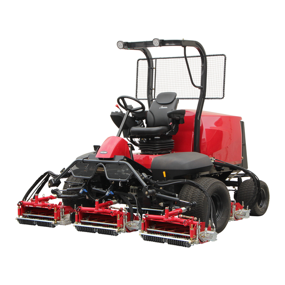
- Page 1 5-Unit Reel Mower Owner's Operating Manual Serial No. LM551B:30001- "Required reading" Read this manual before using the machine. Original Instructions Ver.1.0...
- Page 2 LM551B Regulations California Proposition 65 (For California, USA) WARNING: Operating, servicing and maintaining a passenger vehicle or off-road vehicle can expose you to chemicals including engine exhaust, carbon monoxide, phthalates, and lead, which are known to the State of California to cause cancer and birth defects or other reproductive harm.
- Page 3 LM551B Greeting Thank you for purchasing the Baroness product. This manual describes the proper handling, adjustment, and inspection of your product. We hope you will use the product safely, and take advantage of its best performance. For details on the handling, adjustment and inspection of the attachments, refer to the Owner's Operating Manual for the attachments.
- Page 4 The operator is responsible for operating the product properly and safely. Maintenance service for this machine should be performed by a mechanic with expertise. If you have any questions concerning maintenance or genuine parts, please contact a Baroness dealer or Kyoeisha.
- Page 5 When replacing parts, be sure to use genuine Baroness parts or parts designated by Kyoeisha. Note that the Baroness product warranty may not apply to defects caused by the use of parts from other companies. Prior to use, carefully read the following manuals to thoroughly understand the contents for safe and correct operation.
- Page 6 LM551B Introduction...
-
Page 7: Table Of Contents
LM551B Contents Safety .............. Page 1-1 Safe Operating Practices .......Page 1-2 Disposal ............Page 2-1 Recycle and Waste Disposal ......Page 2-2 Product Overview .......... Page 3-1 Specifications ..........Page 3-2 Names of Each Section ......... Page 3-4 Regulation Decals ..........Page 3-4 Safety Signs and Instruction Signs .... - Page 8 LM551B Contents...
-
Page 9: Safety
LM551B Safety Safe Operating Practices ...... Page 1-2 Training ..........Page 1-2 Preparation ..........Page 1-2 Operation ..........Page 1-3 Maintenance and Storage ..... Page 1-4 Page 1-1... -
Page 10: Safe Operating Practices
LM551B Safety Failure to adequately follow these safety Never allow children or people unfamiliar precautions may cause an accident resulting in with these instructions to use or service the injury or death. machine. Local regulations may restrict the age of the... - Page 11 LM551B Safety Add fuel before starting the engine. Never Never operate across the face of the remove the cap of the fuel tank or add fuel slope, unless the machine is designed for while the engine is running or when the this purpose.
- Page 12 LM551B Safety Never operate while people, especially To reduce the fire hazard, keep the engine, children, or pets are nearby. silencer/muffler, battery compartment fuel storage area, cutting unit and drives free of Slow down and use caution when making grass, leaves, or excessive grease. Clean up turns and crossing roads and sidewalks.
- Page 13 LM551B Safety Make sure that parts such as wires are not touching each other and that their covers have not come off. Use care when checking the cylinders/reels and bed knives. Wear gloves and use caution when servicing them. Be careful during adjustment of the...
- Page 14 LM551B Safety Page 1-6 Safe Operating Practices...
-
Page 15: Disposal
LM551B Disposal Recycle and Waste Disposal ....Page 2-2 About Recycle ........Page 2-2 About Waste Disposal ......Page 2-2 Page 2-1... -
Page 16: Recycle And Waste Disposal
LM551B Disposal Recycle and Waste Disposal About Recycle Recycling battery etc. is recommended for environmental conservation and economical use of resources. It may be required by local laws. About Waste Disposal Make sure that waste generated when servicing or repairing the machine is disposed of in accordance with local regulations. -
Page 17: Product Overview
LM551B Product Overview Specifications ........Page 3-2 Specifications .........Page 3-2 Sound Pressure Level ......Page 3-3 Sound Power Level ....... Page 3-3 Vibration Level ........Page 3-3 Names of Each Section ......Page 3-4 Regulation Decals ........Page 3-4 Positions of Regulation Decals ....Page 3-4 Description of Regulation Decals .. -
Page 18: Specifications
LM551B Product Overview Specifications Specifications Model LM551B Mower unit type 22 in Total length 116.14 in 295 cm Total width 86.61 in 220 cm Dimensions Roof 94.09 in 239 cm Total height Handle 62.99 in 160 cm with Groomer, CR... -
Page 19: Sound Pressure Level
LM551B Product Overview Front wheel 26.5 x 14.00-12 Tire size Rear wheel 20 x 12.00-10 Tire Front wheel 17.40 psi 120 kPa (1.2 kgf/cm pneumatic Rear wheel 20.30 psi 140 kPa (1.4 kgf/cm pressure Battery 105D31L Spark plug The factory default maximum engine rpm is 3,000 rpm. -
Page 20: Names Of Each Section
LM551B Product Overview Names of Each Section Regulation Decals Positions of Regulation Decals 10,11 quwxcl-279 G,H,I Names of Each Section_001 quwxcl-280 Steering wheel Positions of Regulation Decals_001 Tilt lever Serial number plate Seat Specification decal Hood Noise emission decal Radiator cover... -
Page 21: Description Of Regulation Decals
LM551B Product Overview Description of Regulation Decals Noise Emission Decal Serial Number Plate (For Europe) The noise emission decal indicates the sound The serial number plate indicates the model power level determined by measuring and serial number of the machine. -
Page 22: Regulation Decals
LM551B Product Overview ROPS Caution Decal Recycle Decal ROPS caution decal describes the following Recycle Decal illustrates Recycle Mark in caution messages. accordance with local regulation. (For Europe) Replace damaged ROPS. ・ Do not repair or revise. ・ y7wov5-001 Recycle Decal_001... - Page 23 LM551B Product Overview Battery Danger Decal California Proposition 65 Decal (Riding Type) (For USA) (For the State of California, USA) Battery Danger Decal describes handling California Proposition 65 decal describes the precautions for battery. warning messages as required by California Proposition 65.
-
Page 24: Safety Signs And Instruction Signs
6iul4h-209 Positions of Safety Decals and Instruction Decals_002 Part numbers for decals that need to be replaced are listed in the parts catalog. Order them from a Baroness dealer or Kyoeisha. Positions of Safety Decals and Instruction Decals 6iul4h-135... - Page 25 LM551B Product Overview 6iul4h-138 Positions of Safety Decals and Instruction Decals_006 Decal for operation 2 Caution to rotating object decal Caution to hot parts decal Caution to injury decal Caution for mower lock decal Caution to getting pinched decal Fire prohibited decal...
-
Page 26: Description Of Safety Decals And Instruction Decals
LM551B Product Overview Description of Safety Decals and Instruction Decals Caution Rollover - Do not work on slopes of 15 Decal for Operation (E5) degrees or more. STICKER, OPERATION (E5) When you descend a slope, lower the mower LM551B-0604Z0 units and then drive at low speed. - Page 27 LM551B Product Overview Caution to Hot Parts Decal Caution for Mower Lock Decal K4205001540 K4205001900 Decal for caution to hot parts Decal, caution for mower lock Lock the mower units when traveling or Caution storing with the mower units #4 and 5 raised.
- Page 28 LM551B Product Overview Fire Prohibited Decal PTO Caution Decal K4205001940 K4205002000 Decal, fire prohibited Decal, caution PTO Warning Warning Keep away from fire. Watch for rotating parts - Keep your hands away from the joints while the engine is running.
- Page 29 LM551B Product Overview Diesel Fuel Icon Engine Warning Lamp Decal K4209001000 K4205002270 Diesel fuel icon Decal, Engine Warning Lamp Use diesel fuel. fqqeo1-003 xmitt2-001 Engine Warning Lamp Decal_001 Diesel Fuel Icon_001 Caution to Noise Decal DO NOT JACK UP Decal...
- Page 30 LM551B Product Overview Page 3-14 Safety Signs and Instruction Signs...
-
Page 31: Handling Instructions
LM551B Handling Instructions Inspections ..........Page 4-3 Description of Operation Decals ..Page 4-27 Proximity Sensor ........Page 4-31 Daily Check List ........Page 4-3 Relays ..........Page 4-31 Radiator Cover ........Page 4-4 Light Switch ......... Page 4-32 Radiator ..........Page 4-4 Traveling/Working Selector Switch ..Page 4-32 Coolant .......... - Page 32 LM551B Handling Instructions Before Long-Term Storage ....Page 4-84 Page 4-2...
-
Page 33: Inspections
LM551B Handling Instructions Inspections Inspect the machine according to the daily check list so that you will be able to take advantage of its optimum performance for a long period of time. Daily Check List LM551B ○・・・Inspect, adjust, supply, clean ●・・・Replace (first time) -
Page 34: Radiator Cover
LM551B Handling Instructions Radiator Cover Cleaning of Radiator Inspection of Radiator Cover Important Make sure that there is no damage to the An unclean radiator may cause the engine to radiator cover. overheat or seize. Make sure that the radiator cover is not It may also cause malfunction of the hydraulic contaminated. -
Page 35: Coolant
LM551B Handling Instructions Pull up the radiator cover to remove it. Carefully clean the radiator with water or compressed air. Coolant Inspection of Coolant Caution Do not touch the radiator or coolant during engine operation or immediately after the engine has been turned off. -
Page 36: Oil Cooler
LM551B Handling Instructions Coolant Supply Reserve tank Reserve tank cap Caution If no coolant is in the reserve tank, follow Do not touch the radiator or coolant during the steps below to supply clean water. engine operation or immediately after the Open the radiator cap, and then supply engine has been turned off. -
Page 37: Hydraulic Oil
LM551B Handling Instructions If the oil cooler has been contaminated with Supply of Hydraulic Oil dust, be sure to clean it. Especially after operating the machine in a Important dusty environment, it is important to remove dust as soon as possible. -
Page 38: Hydraulic Hoses
LM551B Handling Instructions If the hydraulic oil level is low, follow the Check the pipes and hoses to make sure that steps below to supply oil. there is no oil leakage, circuit damage, looseness, wear, connector looseness, Open the tank cap, and then supply... - Page 39 LM551B Handling Instructions Press the reset button for the evacuator Cleaning of Air Cleaner valve. Caution Implement after the engine and DPF etc. have well cooled down. Otherwise you may get burned. A contaminated air cleaner element may cause malfunction of the engine.
-
Page 40: Battery
LM551B Handling Instructions Battery Inspection of Battery U P P E R L E V E L L O W E R L E V E L Danger Danger Keep away from fire while inspecting or charging the battery. The battery may explode. -
Page 41: Electrical Wiring
LM551B Handling Instructions Belt UPPER LEVEL LOWER LEVEL Inspection of Belt Electrical Wiring Warning Inspection of Electrical Wiring The engine must be stopped when the belt is inspected. Important Electrical short circuit will cause fire, electrical Important leakage and malfunction of electrical equipments. -
Page 42: Engine Oil
LM551B Handling Instructions Engine Oil Important Do not mix different types of engine oil. Inspection of Engine Oil Important Important Securely tighten the oil level gauge and oil Be sure to use engine oil that is classified as filler cap. -
Page 43: Fuel
LM551B Handling Instructions Note: Fuel The factory default low fuel level is 10%.The level can be changed optionally. Inspection of Fuel Quantity With the machine on a level surface, observe the fuel level in the monitor to check the fuel level. -
Page 44: Water Separator
LM551B Handling Instructions Wipe off the spilt oil thoroughly. Draining of Water Separator Important If water contaminates the fuel, the supply pump and injector will seize due to heat. Drain the water in accordance with the Maintenance Schedule. However, when the float is raised by water, drain the water even before the schedule. -
Page 45: Fuel Filter
LM551B Handling Instructions Make sure that the fuel filter is not damaged Cleaning of Water Separator or dirty. Oil Leakage Important Inspection of Oil Leakage If water contaminates the fuel, the supply pump and injector will seize due to heat. -
Page 46: Tightening Torques
LM551B Handling Instructions Tightening Torques Important Refer to the Tightening Torque table. Note that the Baroness product warranty may not apply to defects caused by incorrect or overtorque tightening, etc. Standard Tightening Torques Bolts and Nuts Important A number of bolts are used in each part of this machine. - Page 47 LM551B Handling Instructions General bolt Strength classification 4.8 Nominal diameter tib3yb-001 kgf-cm lb-in 3 - 5 30.59 - 50.99 26.55 - 44.26 7 - 9 71.38 - 91.77 61.96 - 79.66 14 - 19 142.76 - 193.74 123.91 - 168.17 29 - 38 295.71 - 387.49...
- Page 48 LM551B Handling Instructions Hydraulic Hose The tightening torques for union joints and union adaptors with parallel pipe threads (G, PF) are shown in the table below. A union joint or adaptor will not become loose or leak as long as it is tightened by the specified torque.
-
Page 49: Principal Tightening Torques
LM551B Handling Instructions Principal Tightening Torques Tightening Torque by Model LM551 LM551A LM551B Tighten the following bolts and nuts at the torque specified in the table. For thread locking adhesive, apply a middle strength thread locker (ThreeBond 1322 or equivalent anaerobic sealant). -
Page 50: Adjustment Before Work
LM551B Handling Instructions Adjustment before Work Tilt lever FREE (released) Adjustment of Steering Wheel LOCK (locked) Adjustment of Seat Warning Do not make adjustments while traveling since Use the adjustment levers to adjust the seat. doing so is dangerous. Adjust the position to fit the operator. -
Page 51: Adjustment Of Reel Rotation Control Valves
LM551B Handling Instructions Adjustment of Reel Rotation Control Dial Valves Lock nut Indicating screw The reel rotation control valves adjust the rotation speeds of the reel cutters (cutting Important cylinders). Adjust according to the operating conditions. In order to maintain quality mowing, the reel... - Page 52 LM551B Handling Instructions Dial (mower units #1, #4 and #5) Lock nut Specialized wrench (accessory) Note: Raise the lock nut to a position where it will not interfere when the dial is turned. 96fzvf-003 Adjustment of Reel Rotation Control Valves_006...
-
Page 53: Procedure To Start/Stop Engine
30 to 60 seconds to avoid Make sure that the intake heater is exhausting the battery. generating heat, the "BARONESS" logo or "Warming up" message appears in the Sit on the seat. monitor display, and the yellow and red Make sure that you have depressed the LEDs are lit. -
Page 54: Safety Mechanisms
As for starting the engine, the safety device prevents the engine from starting unless it After the "BARONESS" logo and the yellow meets each of the following four conditions. and red LEDs go off and the parameters ・... -
Page 55: Operation Method
LM551B Handling Instructions Engine Overload Warning Buzzer Operation Method If the traveling pedal is depressed and the speed exceeds 12.0 km/h while the pedal Cautions for when You Leave The stopper is in the "Traveling" position and the Machine reel cutters (cutting cylinders) are rotating, a buzzer will sound. - Page 56 LM551B Handling Instructions Key switch decal Engine rotation mark Light switch mark Reel rotation switch mark Mower unit up/down lever decal Traveling/working selector mark Tilt steering decal Parking brake decal BRAKE decal 6n6oux-152 FORWARD decal Positions of Operation Decals_003 BACKWARD decal...
-
Page 57: Description Of Operation Decals
LM551B Handling Instructions Description of Operation Decals Light Switch Mark Key Switch Decal Note: Depending on the specifications, this function Decal, key switch may not be available. This indicates the key switch positions. Light switch mark It illustrates ON/OFF of the light. - Page 58 LM551B Handling Instructions Mower Unit Up/Down Decal Tilt Steering Decal Decal, mower unit up/down K4203001710 This indicates the Up/Down positions of the Decal, tilt steering mower unit. This illustrates the tilt directions of the steering wheel and the locked/free positions.
- Page 59 LM551B Handling Instructions BRAKE Decal Driving Mode Shift Decal K4203001450 K4203001740 Decal, BRAKE Decal, shifting driving mode This indicates brake. This indicates high/low speed. BRAKE 7elqr2-001 kp2t9l-013 BRAKE Decal_001 Driving Mode Shift Decal_001 FORWARD Decal Working speed Traveling speed K4203001430...
- Page 60 LM551B Handling Instructions Lapping Decal Reel Stop Decal K4203001590 K4203001310 Decal, lapping Decal, reel stop This indicates rotational direction of the reel This indicates stop of the reel cutter (cutting cutter (cutting cylinder). cylinder). v57o51-001 if834g-002 Lapping Decal_001 Reel Stop Decal_001...
-
Page 61: Proximity Sensor
LM551B Handling Instructions Proximity Sensor Relays There are four proximity sensors on #1, #2, #4 The relay box is located inside the underseat and #5 mower arm fulcrums. cover. These sensors detect the raised or lowered These relays control traveling/working positions of mower units #1, #2, #4 and #5. -
Page 62: Light Switch
LM551B Handling Instructions Light Switch Note: Depending on the specifications, this function may not be available. Caution The lights provide auxiliary lighting. Do not travel or operate the machine at night or under poor visibility. ufahas-009 The light switch is located in the operation Traveling/Working Selector Switch_001 panel. -
Page 63: Reel Rotation Switch
LM551B Handling Instructions Reel Rotation Switch Reel Forward/Reverse Switch Caution Important Set the reel rotation switch to the "Rotation" Do not switch between “Forward” and position immediately before starting cutting “Reverse” while the reel cutter (cutting work. At all other times, be sure to leave the cylinder) is rotating. -
Page 64: Reel Rotation/Stop Switching Lever
LM551B Handling Instructions Reel Rotation/Stop Switching Lever Mower Unit Up/Down Lever Caution Caution Before operating the reel rotation/stop Before raising or lowering the mower units, switching lever, be sure to set the reel rotation make sure that there are no people around switch to the "Stop"... -
Page 65: Throttle Knob
LM551B Handling Instructions Note: Important When the mower units are raised, the reel cutters (cutting cylinders) stop rotating even if In "Auto regeneration inhibit mode" any DPF the reel rotation switch is set to the "Rotation" regeneration of "Auto regeneration", "Parked position. -
Page 66: Dpf Parked Regeneration Switch
LM551B Handling Instructions When the DPF auto regeneration inhibit switch DPF parked regeneration switch is pressed and set to "Auto regeneration inhibit mode", the monitor displays Auto regeneration When parked regeneration starts, inhibit icon. Regeneration icon in the monitor display changes from blinking to lighting. -
Page 67: Pedal Stopper
LM551B Handling Instructions The height and angle of the traveling pedal can be adjusted to fit the operator. Forward: The height and angle can be adjusted by changing the installation position of the bolt and spring washer. Backward: The height can be adjusted by changing the installation position of the bolt and spring washer. -
Page 68: Brake Pedal
LM551B Handling Instructions Open the protective cover of the USB ports. Brake Pedal Caution When leaving the driver's seat, park the machine on a stable, flat surface and be sure to apply the parking brake. Caution Never park the machine on a slope. -
Page 69: Open-Close Lever
LM551B Handling Instructions Open-Close Lever Radiator cover Rubber catch The open-close lever is located at the lower-left side of the seat. Close the radiator cover slowly. This is used when opening and closing the Lock the rubber catch securely. underseat cover. -
Page 70: Underseat Cover
LM551B Handling Instructions Rubber catch Steering wheel Catch clip Seat Backrest Bolt While unlocking with the open-close lever, grab the grip and tilt the seat to the right to Make sure that the radiator cover is closed. open the underseat cover. -
Page 71: Instruments
LM551B Handling Instructions Displayed Icon Instruments The icon appears at the top of the monitor Description of Monitor display. The monitor displays various information about the machine, such as the operating status and fault conditions. The information of desired items can be confirmed according to operating the keys. -
Page 72: Main Menu Items
LM551B Handling Instructions 4-up display Main Menu Items Four parameters are displayed in the monitor display. While any parameter is displayed, press the With the 4-up display, a total of 8 menu key to display the main menu with the parameters are displayed over 2 pages. - Page 73 LM551B Handling Instructions Parameter Items ■ The parameters and corresponding information that appear in the monitor display are listed below. Monitor display L Monitor display S Description ASH TIMER ASH T This parameter is not used. ENGINE SPEED ENG RPM Displays the engine rpm.
- Page 74 LM551B Handling Instructions Monitor display L Monitor display S Description EXHAUST FILTER Displays the DPF outlet gas temperature measured by the EF OUT T OUTLET TEMP exhaust temperature sensor. Shows the status of the regeneration icon. PARTICUATE TRAP PT LAMP Icon not displayed="OFF", Icon blinking="ON BLINK", Icon...
- Page 75 LM551B Handling Instructions Text 2 ・ Language With "LANGUAGES", the language used in the monitor display can be set to either of the following two. 1 of 4 C : 3 SPN 172 FMI 3 ENGLISH ・ CORRECTIVE ACTION: S e e S e r v i c e M a n u a l ・...
- Page 76 LM551B Handling Instructions List of Fault Codes ■ Important When the fault code appears in the monitor display, refer to "Kubota DIAGNOSIS MANUAL" or contact your dealer. The fault codes (DTC) and corresponding information that appear in the monitor display are listed below.
- Page 77 LM551B Handling Instructions J1939-73 Limp Home Behaviour Corrective Action by Recovery from DTC name ISO 14229 Detected item During action engine ECU error Malfunction Text 1 P-Code <DM> (system action) Text 2 <DM> <DM> <DM> • [Default value] • Sensor/ During start-up •...
- Page 78 LM551B Handling Instructions J1939-73 Limp Home Behaviour Corrective Action by Recovery from DTC name ISO 14229 Detected item During action engine ECU error Malfunction Text 1 P-Code <DM> (system action) Text 2 <DM> <DM> <DM> • Insufficient output kgf/cm , 12000 •...
- Page 79 LM551B Handling Instructions J1939-73 Limp Home Behaviour Corrective Action by Recovery from DTC name ISO 14229 Detected item During action engine ECU error Malfunction Text 1 P-Code <DM> (system action) Text 2 <DM> <DM> <DM> • Output limit: Q • Insufficient value of approx.
- Page 80 LM551B Handling Instructions J1939-73 Limp Home Behaviour Corrective Action by Recovery from DTC name ISO 14229 Detected item During action engine ECU error Malfunction Text 1 P-Code <DM> (system action) Text 2 <DM> <DM> <DM> • Sensor/ • Output limit: Q •...
- Page 81 LM551B Handling Instructions J1939-73 Limp Home Behaviour Corrective Action by Recovery from DTC name ISO 14229 Detected item During action engine ECU error Malfunction Text 1 P-Code <DM> (system action) Text 2 <DM> <DM> <DM> • Output limit: Q value of approx.
- Page 82 LM551B Handling Instructions J1939-73 Limp Home Behaviour Corrective Action by Recovery from DTC name ISO 14229 Detected item During action engine ECU error Malfunction Text 1 P-Code <DM> (system action) Text 2 <DM> <DM> <DM> • Output limit: Q value of approx.
- Page 83 LM551B Handling Instructions J1939-73 Limp Home Behaviour Corrective Action by Recovery from DTC name ISO 14229 Detected item During action engine ECU error Malfunction Text 1 P-Code <DM> (system action) Text 2 <DM> <DM> <DM> • Output limit: Q value of approx.
- Page 84 LM551B Handling Instructions J1939-73 Limp Home Behaviour Corrective Action by Recovery from DTC name ISO 14229 Detected item During action engine ECU error Malfunction Text 1 P-Code <DM> (system action) Text 2 <DM> <DM> <DM> • Faulty starting • Output limit: Q value of approx.
- Page 85 LM551B Handling Instructions J1939-73 Limp Home Behaviour Corrective Action by Recovery from DTC name ISO 14229 Detected item During action engine ECU error Malfunction Text 1 P-Code <DM> (system action) Text 2 <DM> <DM> <DM> • Output limit: Q • Insufficient value of approx.
- Page 86 LM551B Handling Instructions J1939-73 Limp Home Behaviour Corrective Action by Recovery from DTC name ISO 14229 Detected item During action engine ECU error Malfunction Text 1 P-Code <DM> (system action) Text 2 <DM> <DM> <DM> • Short circuit of Stop ENG, •...
- Page 87 LM551B Handling Instructions J1939-73 Limp Home Behaviour Corrective Action by Recovery from DTC name ISO 14229 Detected item During action engine ECU error Malfunction Text 1 P-Code <DM> (system action) Text 2 <DM> <DM> <DM> • Output limit: Torque of 75 % or less •...
- Page 88 LM551B Handling Instructions J1939-73 Limp Home Behaviour Corrective Action by Recovery from DTC name ISO 14229 Detected item During action engine ECU error Malfunction Text 1 P-Code <DM> (system action) Text 2 <DM> <DM> <DM> power supply short See Service 52363 •...
- Page 89 LM551B Handling Instructions J1939-73 Limp Home Behaviour Corrective Action by Recovery from DTC name ISO 14229 Detected item During action engine ECU error Malfunction Text 1 P-Code <DM> (system action) Text 2 <DM> <DM> <DM> • Sensor/ Injector actuation circuit...
- Page 90 LM551B Handling Instructions J1939-73 Limp Home Behaviour Corrective Action by Recovery from DTC name ISO 14229 Detected item During action engine ECU error Malfunction Text 1 P-Code <DM> (system action) Text 2 <DM> <DM> <DM> • Engine stop • Overall •...
- Page 91 LM551B Handling Instructions J1939-73 Limp Home Behaviour Corrective Action by Recovery from DTC name ISO 14229 Detected item During action engine ECU error Malfunction Text 1 P-Code <DM> (system action) Text 2 <DM> <DM> <DM> • Output limit: Q value of approx.
- Page 92 LM551B Handling Instructions J1939-73 Limp Home Behaviour Corrective Action by Recovery from DTC name ISO 14229 Detected item During action engine ECU error Malfunction Text 1 P-Code <DM> (system action) Text 2 <DM> <DM> <DM> • Insufficient • Output limit: •...
- Page 93 LM551B Handling Instructions J1939-73 Limp Home Behaviour Corrective Action by Recovery from DTC name ISO 14229 Detected item During action engine ECU error Malfunction Text 1 P-Code <DM> (system action) Text 2 <DM> <DM> <DM> • [Default value] During start-up Simultaneous •...
- Page 94 LM551B Handling Instructions J1939-73 Limp Home Behaviour Corrective Action by Recovery from DTC name ISO 14229 Detected item During action engine ECU error Malfunction Text 1 P-Code <DM> (system action) Text 2 <DM> <DM> <DM> • Disconnected • Insufficient injector output •...
- Page 95 LM551B Handling Instructions J1939-73 Limp Home Behaviour Corrective Action by Recovery from DTC name ISO 14229 Detected item During action engine ECU error Malfunction Text 1 P-Code <DM> (system action) Text 2 <DM> <DM> <DM> See Service 52359 harness Failure...
- Page 96 LM551B Handling Instructions "RESTORED TO DEFAULTS" appears in Engine Configuration the monitor display, and the parameters are reset to the factory defaults of the This function is not supported. following 8 items. 1-Up Display Setup ENGINE SPEED With "SETUP 1-UP DISPLAY", the displayed...
- Page 97 LM551B Handling Instructions Highlight "CUSTOM SETUP", and then To deselect a parameter and remove it press the Enter key. from the list of displayed parameters The list of parameters appears. Highlight the parameter, and then press the Enter key. USE DEFAULTS...
- Page 98 LM551B Handling Instructions When the parameters are scrolled Automatic Scan ■ automatically, press the Enter key once to pause scrolling. With "AUTOMATIC SCAN", the 1-up display When scrolling is paused, press the Enter can be set to automatically scroll through the key once to restart scrolling.
- Page 99 LM551B Handling Instructions "RESTORED TO DEFAULTS" appears in Highlight "CUSTOM SETUP", and then the monitor display, and the parameters press the Enter key. are reset to the factory defaults of the following 8 items. ・ First page ENGINE SPEED USE DEFAULTS...
- Page 100 LM551B Handling Instructions Use the arrow keys to highlight the Check that a number appeared to the value of the parameter to be changed, right of the selected parameter. and then press the Enter key. The parameters appear. The number at the right of the...
- Page 101 LM551B Handling Instructions Check that the number at the right of Service Reminders the parameter disappeared. With "SERVICE REMINDERS", the notification of replacement time for the following 5 consumables can be specified. Engine oil ・ ENGINE SPEED DRIVERS DEMAND ENGINE TORQUE 4 ACTUAL ENGINE TORQUE ・...
- Page 102 LM551B Handling Instructions Highlight "RESET REMINDER", and then "RESET SERVICE REMINDER?" press the Enter key. appears. To reset, press the Enter key. To cancel resetting, press the menu key. RESET REMINDERS MODIFY REMINDERS RESET SERVICE REMINDER? unpc8m-007 Reset Reminders_002 Use the arrow keys to highlight the item to unpc8m-010 be changed, and then press the Enter key.
- Page 103 LM551B Handling Instructions Highlight "MODIFY REMINDERS", and Highlight the digit to be changed. then press the Enter key. Press the right arrow key to increase the number. Press the left arrow key to change the digit. RESET REMINDERS MODIFY REMINDERS...
- Page 104 LM551B Handling Instructions The display for selecting the item appears. Pressing the Enter key changes the A plus sign appears on the right side of screen from the warning message to the the item with the replacement time period parameter display.
- Page 105 LM551B Handling Instructions Units Adjust Backlight Monitor display ENGLIS METRI METRI With "ADJUST BACKLIGHT", the brightness C KPA C BAR of the monitor display can be adjusted. ASH T Press the right arrow key to make the display ENG RPM brighter.
- Page 106 LM551B Handling Instructions Utilities With "UTILITIES", the remaining fuel volume can be specified and the monitor configuration 0 RPM 83 % can be displayed. ENG RPM % SOOT The following 6 items appear when 19 C NO DATA COOL TEMP FUEL LEVEL "UTILITIES"...
- Page 107 LM551B Handling Instructions Highlight "ANALOG INPUT", and then "LOW FUEL" appears. press the Enter key. LOW FUEL GAGE DATA REMOVE ALL GAGES SOFTWARE VERSION FAULT CONVERSION CANCEL ANALOG INPUT 3nw91f-010 3nw91f-007 Fuel Level_005 Press the right arrow key to increase the Fuel Level_002 Highlight "FUEL LEVEL", and then press...
- Page 108 LM551B Handling Instructions Text 2 ・ Fault Code Displays Important When the fault code (DTC) appears in the 1 of 1 WARNING monitor display, contact your dealer. SPN 96 FMI 17 C O R R E C T I V E A C T I O N :...
- Page 109 LM551B Handling Instructions Text 2 ・ Important The corrective action appears. If the service reminders are configured, the notices of the replacement time period for consumables and the fault code may appear all together. 1 of 1 WARNING If the low fuel level is specified, the notices of...
- Page 110 LM551B Handling Instructions Text 2 ・ The corrective action appears. 1 of 1 WARNING SPN 110 FMI 3 CORRECTIVE ACTION: S e e S e r v i c e M a n u a l < > NEXT HIDE...
- Page 111 LM551B Handling Instructions DPF Regeneration Lamp Engine warning lamp The lighting patterns of engine warning lamp Important are as follows. Note : Do not stop the engine with the DPF PCD means fault codes relevant to Particulate regeneration lamp (LED) turned on.
-
Page 112: Move
LM551B Handling Instructions Engine warning lamp repeats blinking and Slowly depress the traveling pedal. lighting alternately when DTC relevant to/ The machine starts traveling. other than PCD/NCD come up at the same When you take your foot off the traveling time. -
Page 113: Cutting Work
LM551B Handling Instructions Tow hook Caution Open the underseat cover. Note that if you stop operating the mower unit "Underseat Cover" (Page 4-40) up/down lever before the mower units are raised completely, reel rotation may not stop. Turn the unload valve under the seat 1 to 1.5 Reel rotation will be turned on or off based on turns counterclockwise. -
Page 114: Transporting
LM551B Handling Instructions Note: Note: During the work, the reel cutters (cutting When tying down the machine, secure the rope cylinders) will rotate or stop in sync with the up at the following locations. and down motion of the mower units. -
Page 115: Maintenance
LM551B Maintenance Maintenance Precautions ..... Page 5-2 Change of Hydraulic Oil Filter ....Page 5-47 Change of Air Cleaner ......Page 5-49 Maintenance Schedule ......Page 5-2 Change of Engine Oil ......Page 5-49 Adjusted Value ........Page 5-7 Change of Engine Oil Filter ....Page 5-50 Change of Fuel Filter ...... -
Page 116: Maintenance Precautions
Use tools appropriate for each maintenance operation. Important For the safe and best performance of your machine, use Baroness genuine parts for replacement and accessories. Please note that our product warranty may be void if you use non-genuine parts for replacement or accessories. - Page 117 LM551B Maintenance Maintenance Item Remarks Open valve Open air cleaner every week or evacuator valve to ○ ○ daily in dusty remove dust...
- Page 118 LM551B Maintenance Maintenance Item Remarks Replace hydraulic 500 hours ● △ oil filter thereafter Check every 100 hours or every Check exterior of month ...
- Page 119 LM551B Maintenance Maintenance Item Remarks whichever Change engine oil ● △ △ comes earlier Initial 50 hours, thereafter every Replace oil filter 400 hours or ...
- Page 120 LM551B Maintenance Maintenance Item Remarks Check intake hose (After air flow ○ sensor) Check exhaust manifold (Crack, ○ ...
-
Page 121: Adjusted Value
*1: When biodiesel fuel is used, change the fuel filter cartridge, fuel hose and clamp bands with new ・ ones at intervals half of the usual ones. *2: Consult your local Baroness Dealer or local KUBOTA Dealer for this service. ・ ・... -
Page 122: Dpf
LM551B Maintenance Automatic Regeneration About DPF Danger Danger The DPF is a purifying filter that collects PM Since it will become extremely hot around the (soot) from exhaust gas. exhaust outlet during DPF regeneration, do When a certain amount of PM (soot) has... - Page 123 LM551B Maintenance Automatic regeneration is activated only When the conditions for automatic ・ when the auto regeneration inhibit switch regeneration are met, the automatic set to the "Auto regeneration mode". regeneration starts and the regeneration icon changes from blinking to lighting.
- Page 124 LM551B Maintenance ■In PM accumulation "Level 1" or "Level 2": Parked Regeneration Important Danger Danger If ignoring the parked regeneration requirement and continuing traveling or cutting Since it will become extremely hot around the work in PM accumulation "Level 1" or "Level exhaust outlet during DPF regeneration, do 2", PM accumulation level enters "Level 2"...
- Page 125 LM551B Maintenance If the DPF auto regeneration inhibit switch set to the "Auto regeneration inhibit mode," set it to the "Auto regeneration mode." Press the DPF parked regeneration switch. 1 of 2 C : 1 Parked regeneration starts and the...
- Page 126 LM551B Maintenance ■In PM accumulation "Level 4": Manual Regeneration Important Danger Danger If ignoring the manual regeneration requirement and continuing traveling or cutting Since it will become extremely hot around the work in PM accumulation "Level 4", PM exhaust outlet during DPF regeneration, do accumulation level enters "Level 5".
-
Page 127: Replacement Of Dpf
LM551B Maintenance Contact your dealer for manual Park this machine in a safe location. regeneration. Apply the parking brake. Replacement of DPF Stop the engine. Contact your dealer for DPF replacement. When PM accumulates excessively in the DPF ■In the case of "High frequency of or ash accumulates, replace the DPF since the regeneration":... -
Page 128: Conditions For Dpf Regeneration
LM551B Maintenance Conditions for DPF Regeneration PM Accumulation Level Level 0 Danger Danger DPF regeneration is not necessary. Since it will become extremely hot around the exhaust outlet during DPF regeneration, do Level 1 not perform the regeneration in a location where fires may occur. - Page 129 LM551B Maintenance When the conditions for automatic Important regeneration are met, the automatic If auto regeneration is performed during regeneration starts and the regeneration icon changes from blinking to lighting. backlapping operation, the auto regeneration may result in failure. Set the engine rotation speed to 2,200 rpm When auto regeneration starts during or more.
- Page 130 LM551B Maintenance When the DPF auto regeneration inhibit Level 2 switch set to the "Auto regeneration inhibit mode": Danger Danger Since it will become extremely hot around the exhaust outlet during DPF regeneration, do not perform the regeneration in a location where fires may occur.
- Page 131 LM551B Maintenance You can continue to use this machine for ・ traveling and cutting work during DPF auto regeneration. You can not continue to use this machine ・ for traveling and cutting work during DPF 2400 RPM 100 % ENG RPM parked regeneration.
- Page 132 LM551B Maintenance <Parked regeneration> Press the DPF parked regeneration switch. Parked regeneration starts and the These are the conditions for activating ・ regeneration icon changes from blinking to parked regeneration. lighting. The parking brake is applied. When the regeneration completed, the The traveling pedal is in neutral.
- Page 133 LM551B Maintenance These are the statuses in PM accumulation Level 3 "Level 3". Danger Danger Since it will become extremely hot around the exhaust outlet during DPF regeneration, do 1 of 2 C : 1 not perform the regeneration in a location...
- Page 134 LM551B Maintenance Level 4 Danger Danger Since it will become extremely hot around the 1 of 2 C : 1 SPN 3701 FMI 16 exhaust outlet during DPF regeneration, do E x c e s s i v e P M 4 not perform the regeneration in a location <...
- Page 135 LM551B Maintenance Level 5 When PM accumulates excessively in the DPF or ash accumulates, replace the DPF 1 of 2 C : 1 since the regeneration in that case is SPN 3701 FMI 0 E x c e s s i v e P M 5 prohibited.
-
Page 136: Jacking Up The Machine
LM551B Maintenance Jack-Up Points Jacking Up The Machine About Jacking Up The Machine Warning When replacing a tire or beginning any other maintenance or repairs, be sure to chock the wheels to prevent the machine from moving. Before jacking up the machine, park it on a... - Page 137 LM551B Maintenance Front left frame Left pivot rwyt62-105 rwyt62-108 Jack-Up Points_003 Jack-Up Points_006 When jacking up the machine at the left Right pivot pivot, place a block of wood between the left pivot and the frame. Note: Use a block of wood with a height of approximately 130 mm (5.12 in).
-
Page 138: Greasing
LM551B Maintenance Greasing No. of Location greasing About Greasing points Mower arm fulcrum Since there may be adhesion or damage due Lift arm fulcrum to lack of grease on moving parts, they must be greased. Lift arm fulcrum shaft Add urea-based No. - Page 139 LM551B Maintenance Mower unit #3 Lift arm fulcrum There is one greasing point on each lift arm fulcrum connected to the mower unit. Mower unit #1 8bq62b-361 Greasing Points_004 Mower unit #4 8bq62b-364 Greasing Points_007 Mower unit #2 8bq62b-362 Greasing Points_005...
- Page 140 LM551B Maintenance Mower unit #4 Mower unit #5 8bq62b-367 8bq62b-370 Greasing Points_010 Greasing Points_013 Mower unit #5 Swiveling bracket fulcrum There is one greasing point on each swiveling bracket fulcrum connected to the mower unit. Mower unit #2 8bq62b-368 Greasing Points_011...
-
Page 141: Lubrication
LM551B Maintenance Brake pedal shaft fulcrum Rear wheel Left 8bq62b-373 8bq62b-377 Greasing Points_016 Greasing Points_020 Traveling pedal shaft fulcrum Rear wheel Right 8bq62b-374 8bq62b-378 Greasing Points_017 Greasing Points_021 Pedal stopper Joint 8bq62b-375 8bq62b-379 Greasing Points_018 Greasing Points_022 Pivot Lubrication Rear wheel Middle... - Page 142 LM551B Maintenance Lubricating Points Apply lubricant at the following locations every 50 hours of operation. 9llqa9-018 Lubricating Points_003 Mower cylinder spherical bearing There are two locations on each mower cylinder. Mower unit #1 9llqa9-019 9llqa9-016 Lubricating Points_004 Lubricating Points_001 No. of...
- Page 143 LM551B Maintenance 9llqa9-022 9llqa9-026 Lubricating Points_007 Lubricating Points_011 Mower unit #3 Mower unit #5 9llqa9-023 9llqa9-027 Lubricating Points_008 Lubricating Points_012 9llqa9-024 9llqa9-028 Lubricating Points_009 Lubricating Points_013 Mower unit #4 9llqa9-025 Lubricating Points_010 Lubrication Page 5-29...
-
Page 144: Maintenance Work
LM551B Maintenance Swivel the mower unit toward the outside of Maintenance Work the main vehicle. Swiveling Mower Units #2 and #3 Caution Both the reel cutter (cutting cylinder) and the bed knife (bottom blade) are edged tools. Handle them carefully, since they could cut your hands or legs. - Page 145 LM551B Maintenance Mower unit position: Rear Removing/Installing Tires Use the center locking hole (B) for maintenance. Front Tires Follow the steps below to remove the front tires: Loosen the bolts. sibu71-013 Swiveling Mower Units #2 and #3_005 Grip pin Pipe pin...
- Page 146 LM551B Maintenance If the belt tension is incorrect, loosen bolt A Bolt, heat-treated and bolt B (securing the alternator), and then move the alternator to adjust the Securely place the jack beneath the jack-up point of the pivot, and then raise it until the tension.
- Page 147 LM551B Maintenance Adjust the adjustment bolt so that the latch Adjustment of Parking Brake is positioned in the fourth or fifth notch from the top. Caution Make sure that the brake wire is not cracked or damaged. Important Make sure that the brake is effective on slopes and that it is not applied any longer when you release it.
- Page 148 LM551B Maintenance Follow the steps below to adjust the brake. Drive the machine to check the following. Adjust it so that the play of brake wire will be Make sure that the brake is effective when ・ as small as possible with the latch positioned depressing the brake pedal all the way at the first notch from the top.
- Page 149 LM551B Maintenance Adjusting The Neutral Position of The Piston Pump Caution Make sure not to touch rotating tires. Caution While adjusting the neutral position, the machine may start to move. LM551_SP0_076 Securely place jacks beneath the jack-up Adjusting The Neutral Position of The Piston Pump_001...
- Page 150 LM551B Maintenance Adjustment of Stoppers Stopper Important Spring washer The installation method and installation Adjustment of Mower Stopper Pin position of the stoppers differ depending on The mower stopper pin can prevent or allow the mower unit model. tilting of the mower units.
- Page 151 LM551B Maintenance To release: Lock nut Insert the cotter pin into the lower hole in the mower stopper pin. Spring 140.0 mm (5.51 in) Adjustment of Stopper Nuts Note: Depending on the specifications, this function may not be available. The stopper nut adjusts the movement range of the mower unit.
- Page 152 LM551B Maintenance Mower unit #3 Adjustment of Mower Unit Leveling Spring A coil spring is installed on the mower unit coupling. This keeps the mower unit level. Adjust the coil spring with the holes in the lift arm. Mower unit #1...
- Page 153 LM551B Maintenance Adjustment of Positions of Mower Units #2 Coil spring and #3 Lift arm Light spring load (standard position) Important Heavy spring load When the grass catcher is installed, move the Mower unit #5 mower units to the rear position.
- Page 154 LM551B Maintenance When moving to the rear position: ・ Important Loosen bolt A of mower unit #3. Since mower units #2 and #3 are connected, Remove bolts B of mower unit #3. slide them at the same time. Follow the steps below to slide the mower units.
- Page 155 LM551B Maintenance LH52・LS62・LS66 Adjustment of Mower Stopper Adjustment of Mower Stoppers for Mower Unit #1 The mower stopper is installed to prevent the mower unit from interfering with the frame. The attaching direction of the mower stopper for mower unit #1 differs according to the type of mower unit.
- Page 156 LM551B Maintenance Remove the nuts of the mower stopper. Mower unit #3 oxie9a-002 oxie9a-014 Adjustment of Mower Stoppers for Mower Unit #2 and Adjustment of Mower Stoppers for Mower Unit #2 and #3_001 #3_003 Mower stopper front position Spring washer...
- Page 157 LM551B Maintenance LH52・LS62 LS66 Mower unit #3 After installing the mower stoppers, press the stopper auxiliary fitting COMP firmly against the bottom side of the frame and secure it with the bolts. oxie9a-010 Adjustment of Mower Stoppers for Mower Unit #2 and...
- Page 158 LM551B Maintenance LH52・LS62 Change of Coolant Caution Do not touch the radiator or coolant during engine operation or immediately after the engine has been turned off. Otherwise, you may get burned. Caution oxie9a-016 Change coolant after the engine has well cooled down.
- Page 159 LM551B Maintenance Relationship between concentration of long-life Remove the reserve tank. coolant (LLC) and freezing temperature LLC concentration Freezing temperature (volume %) Down to -10 °C (14 °F) 20 % Down to -15 °C (5 °F) 30 % Down to -20 °C (-4 °F) 35 % Down to -25 °C (-13 °F)
- Page 160 LM551B Maintenance Remove the drain plug of the hydraulic Change of Hydraulic Oil tank and drain the old oil into a bowl. Install the drain plug. Caution Be careful with hot oil, which could cause burns if it contacts your skin.
- Page 161 LM551B Maintenance Remove the old filter cartridge. Change of Hydraulic Oil Filter Change of Hydraulic Oil Line Filter Caution Be careful with hot oil, which could cause burns if it contacts your skin. Important When replacing the hydraulic oil filter, be sure...
- Page 162 LM551B Maintenance Change of Hydraulic Suction Filter Filter case O-ring Caution Install the filter case onto the body, firmly hand-tighten it, and then tighten it to 25 to Be careful with hot oil, which could cause 35 N·m (254.93 to 356.90 kgf-cm).
- Page 163 LM551B Maintenance Firmly tighten the filter cartridge by hand so Change of Engine Oil that the packing contacts the mounting surface. Caution Then, tighten it an additional 1/2 turn. Be careful with hot oil, which could cause burns if it contacts your skin.
- Page 164 LM551B Maintenance Remove the oil filler cap, and then supply With the filter wrench, remove the old filter new engine oil until the oil reaches a level in cartridge. between the upper and lower limit lines on the oil level gauge.
- Page 165 LM551B Maintenance Change of Fuel Filter Cartridge Packing Important Cover Air-bleeding plug During installation, prevent contamination with O-ring dirt or dust. If the fuel is contaminated with dirt, dust, etc., When the ignition key is set to the "ON" the fuel injection pump and injection nozzle position and the fuel pump is operated after will become worn.
- Page 166 LM551B Maintenance The machine uses a mini fuse for Change of Fuse automobiles. Replace an old fuse with a new fuse of the Important specified capacity. When performing maintenance on the electrical system, be sure to remove the negative battery wire.
- Page 167 LM551B Maintenance Fusible Link Fuse Fuse capacities of the fusible links are 30 A, The fuse in the main harness is for USB 50 A and 80 A. socket and LED work lamp. Depending on the specifications, the LED ・...
- Page 168 LM551B Maintenance Page 5-54 Maintenance Work...
- Page 172 1-26, Miyuki-cho, Toyokawa-city, Tel : +81 - 533 - 84 - 1390 Head Office Fax : +81 - 533 - 84 - 1220 Aichi-pref, 442-8530 JAPAN LM551B--UM--GBZ/21H-00-S.K E00a[LM551B_EU00a]...
Need help?
Do you have a question about the LM551B and is the answer not in the manual?
Questions and answers