
Related Manuals for Baroness LM551


Summary of Contents for Baroness LM551
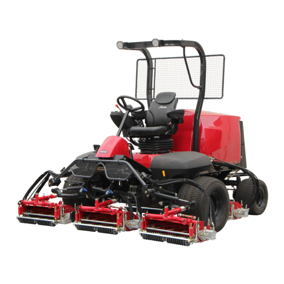
- Page 1 5-Unit Reel Mower Owner's Operating Manual Serial No. LM551:10087- "Required reading" Read this manual before using the machine. Original Instructions Ver.1.3...
- Page 2 LM551 Greeting Thank you for purchasing the Baroness product. This manual describes the proper handling, adjustment, and inspection of your product. We hope you will use the product safely, and take advantage of its best performance. For details on the handling, adjustment and inspection of the attachments, refer to the Owner's Operating Manual for the attachments.
- Page 3 The operator is responsible for operating the product properly and safely. Maintenance should only be performed by a certified specialist. If you have any questions concerning maintenance or genuine parts, please contact a Baroness dealer or Kyoeisha. When making inquiries about the product, please specify the product's model designation and serial number.
- Page 4 When replacing parts, be sure to use genuine Baroness parts or parts designated by Kyoeisha. Note that the Baroness product warranty may not apply to defects caused by the use of parts from other companies. Prior to use, carefully read the following manuals to thoroughly understand the contents for safe and correct operation.
-
Page 5: Table Of Contents
LM551 Contents Safety .............. Page 1-1 Safe Operating Practices .......Page 1-2 Disposal ............Page 2-1 Recycle and Waste Disposal ......Page 2-2 Product Overview .......... Page 3-1 Specifications ..........Page 3-2 Names of Each Section ......... Page 3-4 Regulation Decals ..........Page 3-4 Safety Signs and Instruction Signs .... - Page 6 LM551 Contents...
-
Page 7: Safety
LM551 Safety Safe Operating Practices ...... Page 1-2 Training ..........Page 1-2 Preparation ..........Page 1-2 Operation ..........Page 1-3 Maintenance and Storage ..... Page 1-4 Page 1-1... -
Page 8: Safe Operating Practices
LM551 Safety Failure to adequately follow these safety Never allow children or people unfamiliar precautions may cause an accident resulting in with these instructions to use or service the injury or death. machine. Local regulations may restrict the age of the... - Page 9 LM551 Safety Exercise care in the handling of fuel. Remember there is no such thing as a safe slope. Travel on grass slopes requires Warning particular care. To guard against overturning: Warning-Fuel is highly flammable. Take the following precautions. Do not stop or start suddenly when going up or downhill.
- Page 10 LM551 Safety Before checking, cleaning, or working the Reduce the throttle setting during engine machine. run-out and, if the engine is provided with a shut-off valve, turn the fuel off at the After striking a foreign object or if an conclusion of operation.
- Page 11 LM551 Safety When checking the hydraulic circuit for pinhole leaks or oil leakage from nozzles, do not use your hands. Use items such as paper or corrugated cardboard to find leakage points. Be extremely careful with high-pressure oil as it may pierce your skin, resulting in an injury.
- Page 12 LM551 Safety Page 1-6 Safe Operating Practices...
-
Page 13: Disposal
LM551 Disposal Recycle and Waste Disposal ....Page 2-2 About Recycle ........Page 2-2 About Waste Disposal ......Page 2-2 Page 2-1... -
Page 14: Recycle And Waste Disposal
LM551 Disposal Recycle and Waste Disposal About Recycle Recycling battery etc. is recommended for environmental conservation and economical use of resources. It may be required by local laws. About Waste Disposal Make sure that waste generated when servicing or repairing the machine is disposed of in accordance with local regulations. -
Page 15: Product Overview
LM551 Product Overview Specifications ........Page 3-2 Specifications .........Page 3-2 Sound Pressure Level ......Page 3-3 Sound Power Level ....... Page 3-3 Vibration Level ........Page 3-3 Names of Each Section ......Page 3-4 Regulation Decals ........Page 3-4 Positions of Regulation Decals ....Page 3-4 Description of Regulation Decals .. -
Page 16: Specifications
LM551 Product Overview Specifications Specifications Model LM551 Mower unit type 22 in 26 in Total length 116.14 in 295 cm ← ← Total width 86.61 in 220 cm ← ← Dimensi Roof 94.09 in 239 cm ← ← Total height Handle 62.99 in... -
Page 17: Sound Pressure Level
LM551 Product Overview 10.0 dm (10.0 Coolant volume 2.64 U.S.gals ← ← 30.3 dm (30.3 Hydraulic tank capacity 8.01 U.S.gals ← ← Operating width (Mowing width) 100.00 in 254 cm 111.02 in 282 cm 0.197 - 0.787 LH52 5.0 - 20.0 mm ←... -
Page 18: Names Of Each Section
LM551 Product Overview Names of Each Section Regulation Decals Positions of Regulation Decals 10,11 quwxcl-182 Names of Each Section_001 quwxcl-183 Steering wheel Positions of Regulation Decals_001 Tilt lever Serial number plate Seat Specification decal Hood Noise emission decal Radiator cover... -
Page 19: Regulation Decals
LM551 Product Overview Description of Regulation Decals Year of Manufacture Decal Serial Number Plate (For Europe) The year of manufacture decal indicates the The serial number plate indicates the model year when this machine was manufactured. and serial number of the machine. -
Page 20: Safety Signs And Instruction Signs
If they are damaged, become dirty, or peel off, replace them with new ones. Part numbers for decals that need to be replaced are listed in the parts catalog. Order them from a Baroness dealer or Kyoeisha. 2z2dxu-001 Positions of Safety Decals and Instruction... - Page 21 LM551 Product Overview 6iul4h-134 6iul4h-138 Positions of Safety Decals and Instruction Decals_002 Positions of Safety Decals and Instruction Decals_006 Decal for operation 2 Caution to rotating object decal Caution to hot parts decal Caution to injury decal Caution for mower lock decal...
-
Page 22: Description Of Safety Decals And Instruction Decals
LM551 Product Overview Description of Safety Decals and Instruction Decals Caution Rollover - Do not work on slopes of 15 Decal for Operation 2 degrees or more. Decal for operation 2 When you descend a slope, lower the mower LM2400-0918Z0 units and then drive at low speed. - Page 23 LM551 Product Overview Caution to Hot Parts Decal Caution for Mower Lock Decal K4205001540 K4205001900 Decal for caution to hot parts Decal, caution for mower lock Lock the mower units when traveling or Caution storing with the mower units #4 and 5 raised.
- Page 24 LM551 Product Overview Fire Prohibited Decal PTO Caution Decal K4205001940 K4205002000 Decal, fire prohibited Decal, caution PTO Warning Warning Keep away from fire. Watch for rotating parts - Keep your hands away from the joints while the engine is running.
- Page 25 LM551 Product Overview Diesel Fuel Icon Caution to Noise Decal K4209001000 K4205002090 Diesel fuel icon Decal, caution to noise Use diesel fuel. bwu9po-001 xmitt2-001 Caution to Noise Decal_001 Diesel Fuel Icon_001 DO NOT JACK UP Decal K4205002220 Decal, DO NOT JACK UP Do not jack up.
- Page 26 LM551 Product Overview Page 3-12 Safety Signs and Instruction Signs...
-
Page 27: Handling Instructions
LM551 Handling Instructions Inspections ..........Page 4-2 Description of Operation Decals ..Page 4-26 Proximity Sensor ........Page 4-29 Radiator Cover ........Page 4-2 Relays ..........Page 4-30 Radiator ..........Page 4-2 Light Switch ......... Page 4-31 Coolant ..........Page 4-3 Traveling/Working Selector Switch ..Page 4-31 Oil Cooler ..........Page 4-5... -
Page 28: Inspections
LM551 Handling Instructions Make sure that the radiator is not Inspections contaminated. Inspect the machine according to the Cleaning of Radiator maintenance schedule so that you will be able to take advantage of its optimum performance for a Important long period of time. -
Page 29: Coolant
LM551 Handling Instructions Pull up the radiator cover to remove it. Carefully clean the radiator with water or compressed air. Coolant Inspection of Coolant Caution Do not touch the radiator or coolant during engine operation or immediately after the engine has been turned off. - Page 30 LM551 Handling Instructions If no coolant is in the reserve tank, follow Coolant Supply the steps below to supply clean water. Open the radiator cap, and then supply Caution clean water up to the opening. Do not touch the radiator or coolant during...
-
Page 31: Oil Cooler
LM551 Handling Instructions Oil Cooler Hydraulic Oil Inspection of Oil Cooler Inspection of Hydraulic Oil Make sure that there is no damage to the The oil gauge is on the side of the hydraulic oil cooler. tank. Make sure that the oil cooler is not Raise the mower units and maintain that contaminated. -
Page 32: Air Cleaner
LM551 Handling Instructions Tank cover Screw If the hydraulic oil level is low, follow the steps below to supply oil. Open the tank cap, and then supply hydraulic oil through the oil filling port until the oil level reaches the middle of the oil gauge on the hydraulic tank. -
Page 33: Battery
LM551 Handling Instructions Battery Inspection of Battery Danger Danger Keep away from fire while inspecting or charging the battery. The battery may explode. yt4sup-016 Warning Cleaning of Air Cleaner_001 Do not allow the battery fluid level to become Air cleaner element... -
Page 34: Tire
LM551 Handling Instructions U P P E R L E V E L U P P E R L E V E L L O W E R L E V E L L O W E R L E V E L... -
Page 35: Belt
LM551 Handling Instructions Belt Engine Oil Inspection of Belt Inspection of Engine Oil Warning Important The engine must be stopped when the belt is Securely tighten the oil level gauge and oil inspected. filler cap. Check the oil level 10 to 20 minutes after Important stopping the engine. -
Page 36: Fuel
LM551 Handling Instructions Fuel Supply of Engine Oil Inspection of Fuel Quantity Important With the machine on a level surface, observe Do not supply too much engine oil. Otherwise, the fuel gauge in the operation panel to check the engine may be damaged. -
Page 37: Water Separator
LM551 Handling Instructions Set the ignition key to the "OFF" position. 2e4emp-012 kou8ls-009 Supply of Fuel_001 Air Bleeding of Fuel System_001 Fuel tank Air-bleed plug Tank cap Injection pump Air Bleeding of Fuel System Fuel filter Water Separator Important The air-bleed plug should always be in the... - Page 38 LM551 Handling Instructions Drain the water from the cup. Draining of Water Separator Important Important During installation, prevent contamination with dirt or dust. Water-contaminated fuel may impair engine If the fuel is contaminated with dirt, dust, etc., startability, decrease output or damage engine the fuel injection pump and injection nozzle parts.
- Page 39 LM551 Handling Instructions Drain the water from the cup. Cleaning of Water Separator Clean the cup and element with diesel fuel. Important Important Water-contaminated fuel may impair engine During installation, prevent contamination with startability, decrease output or damage engine dirt or dust.
-
Page 40: Fuel Filter
LM551 Handling Instructions Fuel Filter Inspection of Fuel Filter The fuel filter works to remove foreign objects mixed into the fuel. When the fuel flow becomes insufficient, replace the fuel filter if necessary. Make sure that there is no fuel leakage. -
Page 41: Tightening Torques
LM551 Handling Instructions Tightening Torques Important Refer to the Tightening Torque table. Note that the Baroness product warranty may not apply to defects caused by incorrect or overtorque tightening, etc. Standard Tightening Torques Bolts and Nuts Important A number of bolts are used in each part of this machine. - Page 42 LM551 Handling Instructions General bolt Strength classification 4.8 Nominal diameter tib3yb-001 kgf-cm lb-in 3 - 5 30.59 - 50.99 26.55 - 44.26 7 - 9 71.38 - 91.77 61.96 - 79.66 14 - 19 142.76 - 193.74 123.91 - 168.17 29 - 38 295.71 - 387.49...
-
Page 43: Principal Tightening Torques
LM551 Handling Instructions Principal Tightening Torques Tightening Torque by Model LM551 LM551A Tighten the following bolts and nuts at the torque specified in the table. For thread locking adhesive, apply a middle strength thread locker (ThreeBond 1322 or equivalent anaerobic sealant). -
Page 44: Adjustment Before Work
LM551 Handling Instructions Adjustment before Work Tilt lever FREE (released) Adjustment of Steering Wheel LOCK (locked) Adjustment of Seat Warning Do not make adjustments while traveling since Use the adjustment levers to adjust the seat. doing so is dangerous. Adjust the position to fit the operator. -
Page 45: Adjustment Of Reel Rotation Control Valves
LM551 Handling Instructions Adjustment of Reel Rotation Control Dial Valves Lock nut Indicating screw The reel rotation control valves adjust the rotation speeds of the reel cutters (cutting Important cylinders). Adjust according to the operating conditions. In order to maintain quality mowing, the reel... -
Page 46: Adjustment Of Mower Stopper Pin
LM551 Handling Instructions Dial (mower units #1, #4 and #5) Lock nut Specialized wrench (accessory) Note: Raise the lock nut to a position where it will not interfere when the dial is turned. 96fzvf-003 Adjustment of Reel Rotation Control Valves_006... -
Page 47: Adjustment Of Mower Stabilizer
LM551 Handling Instructions To fix: The mower stabilizer stabilizes the mower units Insert the cotter pin into the upper hole in the and prevents an undulating finish (a mower stopper pin. phenomenon called Marcelling). On a level surface, lower all mower units. -
Page 48: Procedure To Start/Stop Engine
LM551 Handling Instructions Adjustment of Stopper Nuts Procedure to Start/Stop Engine Note: Start/Stop of Engine Depending on the specifications, this function Procedure to Start Engine may not be available. The stopper nut adjusts the movement range Caution of the mower unit. - Page 49 LM551 Handling Instructions Move the throttle lever from the "Low After the thermo-start lamp turns off, speed” position halfway toward the "High immediately set the ignition key to the speed” position. "START" position. Important Important The thermo-start lamp turns off at the Quickly returning the ignition key from the specified time.
-
Page 50: Safety Mechanisms
LM551 Handling Instructions Close the fuel cock of the water separator. Engine Overload Warning Buzzer If the traveling pedal is depressed and the Safety Mechanisms speed exceeds 12.0 km/h while the pedal stopper is in the "Traveling" position and the... -
Page 51: Operation Method
LM551 Handling Instructions Operation Method Cautions for when You Leave The Machine Caution LAPP ING If the brakes are not sufficiently effective, use the wheel stoppers to secure the machine. 6n6oux-153 Caution Positions of Operation Decals_004 Never park the machine on a slope. -
Page 52: Description Of Operation Decals
LM551 Handling Instructions Description of Operation Decals Light Switch Mark Key Switch Decal Note: Depending on the specifications, this function Key switch decal may not be available. This indicates the key switch positions. Light switch mark It illustrates ON/OFF of the light. - Page 53 LM551 Handling Instructions Mower Unit Up/Down Decal Tilt Steering Decal Decal, mower unit up/down K4203001710 This indicates the Up/Down positions of the Decal, tilt steering mower unit. This illustrates the tilt directions of the steering wheel and the locked/free positions.
- Page 54 LM551 Handling Instructions BRAKE Decal Driving Mode Shift Decal K4203001450 K4203001740 Decal, BRAKE Decal, shifting driving mode This indicates brake. This indicates high/low speed. BRAKE 7elqr2-001 kp2t9l-013 BRAKE Decal_001 Driving Mode Shift Decal_001 FORWARD Decal Working speed Traveling speed K4203001430...
-
Page 55: Proximity Sensor
LM551 Handling Instructions Lapping Decal Reel Stop Decal K4203001590 K4203001310 Decal, lapping Decal, reel stop This indicates rotational direction of the reel This indicates stop of the reel cutter (cutting cutter (cutting cylinder). cylinder). v57o51-001 if834g-002 Lapping Decal_001 Reel Stop Decal_001... -
Page 56: Relays
LM551 Handling Instructions Mower unit #2 ・ Relays The relay box is located inside the underseat cover. These relays control traveling/working selection, rotation of the reel cutters (cutting cylinders), and mower unit lowering selection. The operating condition can be checked by the illumination of the LEDs. -
Page 57: Light Switch
LM551 Handling Instructions The traveling/working selector switch is located Light Switch in the operation panel. This can change the positions where mower Caution units #4 and #5 stop when they are raised. The lights provide auxiliary lighting. Do not travel or operate the machine at night or under poor visibility. -
Page 58: Reel Rotation Switch
LM551 Handling Instructions Reel Rotation Switch Important If the reel rotation switch is not set to the Caution "Rotation" position, the reel cutter (cutting cylinder) will not rotate. Set the reel rotation switch to the "Rotation" position immediately before starting cutting The reel forward/reverse switch is located work. -
Page 59: Reel Rotation/Stop Switching Lever
LM551 Handling Instructions Reel Rotation/Stop Switching Lever Mower Unit Up/Down Lever Caution Caution Before operating the reel rotation/stop Before raising or lowering the mower units, switching lever, be sure to set the reel rotation make sure that there are no people around switch to the "Stop"... -
Page 60: Throttle Lever
LM551 Handling Instructions Note: The height and angle of the traveling pedal can When the mower units are raised, the reel be adjusted to fit the operator. cutters (cutting cylinders) stop rotating even if Forward: the reel rotation switch is set to the "Rotation"... -
Page 61: Pedal Stopper
LM551 Handling Instructions Pedal Stopper Important When the traveling speed exceeds 12.0 km/h during cutting operation, a buzzer will sound. If the operation continues, the engine and hydraulic equipments will be damaged. The pedal stopper is located in the right foot area. -
Page 62: Open-Close Lever
LM551 Handling Instructions Brake pedal Radiator cover Locking pedal Rubber catch Open-Close Lever Close the radiator cover slowly. Lock the rubber catch securely. The open-close lever is located at the lower-left Hood side of the seat. This is used when opening and closing the underseat cover. -
Page 63: Underseat Cover
LM551 Handling Instructions Rubber catch Steering wheel Catch clip Seat Backrest Bolt While unlocking with the open-close lever, grab the grip and tilt the seat to the right to Make sure that the radiator cover is closed. open the underseat cover. -
Page 64: Instruments
LM551 Handling Instructions Fuel Gauge Instruments The fuel gauge is located in the operation Instruments on The Operation Panel panel. This instrument indicates the quantity of fuel inside the fuel tank. F U E L kz7ka6-015 Instruments on The Operation Panel_001... -
Page 65: Travel Of Machine
LM551 Handling Instructions Hour Meter Thermo-Start Lamp The thermo-start lamp is the middle pilot lamp The hour meter is located in the operation located in the operation panel. panel, and indicates the accumulated operation When the ignition key is set to the "GLOW"... -
Page 66: Towing The Machine
LM551 Handling Instructions Turn the unload valve under the seat 1 to 1.5 Towing The Machine turns counterclockwise. If the machine does not travel due to engine trouble, etc., you can move it in the following ways: Caution Do not touch the unload valve except when towing the machine. -
Page 67: Cutting Work
LM551 Handling Instructions Set the traveling/working selector switch to Cutting Work the "Working" position. Cutting Work Shift the mower unit up/down lever to the "Down" position to lower the mower units. Warning Set the reel rotation switch to the "Rotation"... -
Page 68: Transporting
LM551 Handling Instructions bos35l-003 4xt2ml-001 Removal/Installation of Grass Catcher_001 Transporting Procedure_002 Grass catcher Bumper Grass catcher mounting bracket Storage Mounting pin Before Long-Term Storage Transporting Remove dirt, grass clippings, debris, oil ・ Transporting Procedure stains etc. completely. Supply oil and apply grease to appropriate ・... -
Page 69: Maintenance
LM551 Maintenance Maintenance Precautions ..... Page 5-2 Maintenance Schedule ......Page 5-2 Adjusted Value ........Page 5-7 Jacking Up The Machine .......Page 5-8 About Jacking Up The Machine .....Page 5-8 Jack-Up Points ........Page 5-8 Greasing ..........Page 5-9 About Greasing ........Page 5-9 Greasing Points ........ -
Page 70: Maintenance Precautions
Use tools appropriate for each maintenance operation. Important For the safe and best performance of your machine, use Baroness genuine parts for replacement and accessories. Please note that our product warranty may be void if you use non-genuine parts for replacement or accessories. - Page 71 LM551 Maintenance Maintenance Item Remarks Check traveling ○ pedal motion Check brake ○ ...
- Page 72 LM551 Maintenance Maintenance Item Remarks Check looseness of 100 hours ○ ○ wheel mounting bolt thereafter 50 hours first check, every 100 hours thereafter.
- Page 73 LM551 Maintenance Maintenance Item Remarks Check every 100 hours or Check exterior of every month ○ ○ battery whichever comes earlier Check every 100 hours or...
- Page 74 LM551 Maintenance Maintenance Item Remarks Check closed ○ breather hoses Grease mower unit hydraulic motor ○ ...
-
Page 75: Adjusted Value
Replace brake pads △ ・ *1: Consult your local Baroness Dealer or local KUBOTA Dealer for this service. The items above (*2 marked) are registered as emission related critical parts by KUBOTA in the ・ U.S. EPA nonroad emission regulation. -
Page 76: Jacking Up The Machine
LM551 Maintenance Jacking Up The Machine Jack-up points Front right frame About Jacking Up The Machine Front left frame Right pivot Warning Left pivot When replacing a tire or beginning any other Front right frame maintenance or repairs, be sure to chock the wheels to prevent the machine from moving. -
Page 77: Greasing
LM551 Maintenance Greasing About Greasing Since there may be adhesion or damage due to lack of grease on moving parts, they must be greased. Add urea-based No. 2 grease in accordance with the Maintenance Schedule. Other locations where the specified grease or lubricant is used are indicated in "Greasing... - Page 78 LM551 Maintenance Mower unit #3 No. of Location greasing points Mower arm fulcrum Lift arm fulcrum Lift arm fulcrum shaft Swiveling bracket fulcrum Brake pedal shaft fulcrum Traveling pedal shaft fulcrum Pedal stopper 8bq62b-361 Pivot Greasing Points_004 Joint Mower unit #4...
- Page 79 LM551 Maintenance Lift arm fulcrum Mower unit #4 There is one greasing point on each lift arm fulcrum connected to the mower unit. Mower unit #1 8bq62b-367 Greasing Points_010 Mower unit #5 8bq62b-364 Greasing Points_007 Mower unit #2 8bq62b-368 Greasing Points_011...
- Page 80 LM551 Maintenance Mower unit #5 Brake pedal shaft fulcrum 8bq62b-370 8bq62b-373 Greasing Points_013 Greasing Points_016 Swiveling bracket fulcrum Traveling pedal shaft fulcrum There is one greasing point on each swiveling bracket fulcrum connected to the mower unit. Mower unit #2...
-
Page 81: Lubrication
LM551 Maintenance Rear wheel Left Lubrication About Lubrication It is necessary to lubricate moving parts so that they will not become stuck or damaged. The locations where lubricant is used are indicated in "Lubricating Points". Apply the lubricant. Lubricating Points... - Page 82 LM551 Maintenance Steering cylinder spherical bearing There are two locations. 9llqa9-020 Lubricating Points_005 9llqa9-017 Mower unit #2 Lubricating Points_002 9llqa9-021 9llqa9-018 Lubricating Points_006 Lubricating Points_003 Mower cylinder spherical bearing There are two locations on each mower cylinder. Mower unit #1...
-
Page 83: Maintenance Work
LM551 Maintenance 9llqa9-024 9llqa9-028 Lubricating Points_009 Lubricating Points_013 Mower unit #4 Maintenance Work Swiveling Mower Units #2 and #3 Caution Both the reel cutter (cutting cylinder) and the bed knife (bottom blade) are edged tools. Handle them carefully, since they could cut your hands or legs. -
Page 84: Swiveling Mower Units #2 And #3
LM551 Maintenance Swivel the mower unit toward the outside of Hydraulic hose the main vehicle. Muffler Exhaust gas Mower unit swivel angle 90° Mower unit swivel angle 45° sibu71-011 Swiveling Mower Units #2 and #3_004 Mower unit Fully insert the grip pin into the locking hole... - Page 85 LM551 Maintenance Mower unit position: Rear Use the center locking hole (B) for maintenance. sibu71-013 Swiveling Mower Units #2 and #3_006 Grip pin Pipe pin Start the engine, and then raise the mower units. sibu71-014 Swiveling Mower Units #2 and #3_007...
-
Page 86: Removing/Installing Tires
LM551 Maintenance Removing/Installing Tires Bolt, heat-treated Securely place the jack beneath the jack-up Front Tires point of the pivot, and then raise it until the Follow the steps below to remove the front tires lift off the ground. tires: "Jack-Up Points" (Page 5-8) Loosen the bolts. -
Page 87: Adjustment Of Parking Brake
LM551 Maintenance Brake pedal Latch Notch Fourth or fifth notch Adjust the adjustment bolt so that the latch is positioned in the fourth or fifth notch from the top. mzdn8n-004 Fan Belt_001 Fan Belt Blade Alternator Bolt A Bolt B 10 mm (0.39 in) - Page 88 LM551 Maintenance ulabms-013 nfzln9-025 Adjustment of Brake_001 Adjustment of Brake_003 Brake wire Brake wire Adjustment bolt Adjustment bolt Lock nut Lock nut Brake pedal Stop the engine. Start the engine. Remove the step cover. Drive the machine to check the following.
-
Page 89: Adjusting The Neutral Position Of The Piston Pump
LM551 Maintenance Find the position where all tires stop, and Adjusting The Neutral Position of The then, while holding the traction adjusting Piston Pump cam in place, secure it with the lock nut. Caution Make sure not to touch rotating tires. -
Page 90: Adjustment Of Stoppers
LM551 Maintenance B: Installed at the upper position Control arm LH62 ・ Spring washer Washer Bolt Adjustment of Stoppers Important The installation method and installation position of the stoppers differ depending on the mower unit model. euiiz5-002 Adjustment of Stoppers_002... - Page 91 LM551 Maintenance Mower unit #2 Coil spring Lift arm Light spring load (standard position) Heavy spring load 26 in mower unit imue1o-004 Adjustment of Mower Unit Leveling Spring_002 Coil spring Lift arm 22 in mower unit imue1o-006 26 in mower unit...
-
Page 92: Adjustment Of Positions Of Mower Units #2 And #3
LM551 Maintenance 26 in mower unit Important Since mower units #2 and #3 are connected, slide them at the same time. Follow the steps below to slide the mower units. When moving to the front position: ・ Loosen bolt A of mower unit #3. -
Page 93: Adjustment Of Mower Stopper
LM551 Maintenance Remove bolts B of mower unit #3. The attaching direction of the mower stopper for mower unit #1 differs according to the type of mower unit. Install in the appropriate direction. Loosen the nuts of the right and left mower stoppers. - Page 94 LM551 Maintenance LH52・LS62・LS66 Remove the nuts of the mower stopper. oxie9a-008 oxie9a-002 Adjustment of Mower Stoppers for Mower Unit #1_002 Adjustment of Mower Stoppers for Mower Unit #2 and #3_001 Mower stopper Bolt Spring washer Spring washer Washer Washer Adjust the mower stopper position.
- Page 95 LM551 Maintenance Mower unit #3 LH52・LS62 oxie9a-014 oxie9a-010 Adjustment of Mower Stoppers for Mower Unit #2 and Adjustment of Mower Stoppers for Mower Unit #2 and #3_003 #3_005 Mower stopper front position Mower stopper Mower stopper rear position Front Rear Attach the mower stoppers temporarily.
- Page 96 LM551 Maintenance LS66 LH52・LS62 Mower unit #3 After installing the mower stoppers, press the stopper auxiliary fitting COMP firmly against the bottom side of the frame and secure it with the bolts. oxie9a-016 Adjustment of Mower Stoppers for Mower Unit #4 and...
-
Page 97: Change Of Coolant
LM551 Maintenance Change of Coolant LLC concentration Freezing temperature (volume %) Caution Down to -10 °C (14 °F) 20 % Down to -15 °C (5 °F) 30 % Do not touch the radiator or coolant during Down to -20 °C (-4 °F) -
Page 98: Change Of Hydraulic Oil
LM551 Maintenance Remove the reserve tank. Change of Hydraulic Oil Caution Be careful with hot oil, which could cause burns if it contacts your skin. Important When you change the hydraulic oil, be sure to drain it into a container and discard it in ouuoov-019 accordance with local laws and regulations. -
Page 99: Change Of Hydraulic Oil Filter
LM551 Maintenance Open the tank cap, and then pour new oil Important from the fill port until the oil level reaches the middle of the oil gauge on the hydraulic tank. If the hydraulic oil emulsifies or if it becomes... - Page 100 LM551 Maintenance Lightly coat the O-ring of the new filter Filter cartridge cartridge with hydraulic oil, and then install Filter case the cartridge. Body Supply hydraulic oil until it reaches the specified level. "Supply of Hydraulic Oil" (Page 4-5) Start the engine, and then after the hydraulic oil has warmed up, stop the engine.
-
Page 101: Change Of Air Cleaner
LM551 Maintenance Replace the air cleaner element by following Filter protection plate the same steps as for cleaning the air Bolt cleaner. Filter cartridge "Cleaning of Air Cleaner" (Page 4-6) Remove the old filter cartridge. Change of Engine Oil Lightly coat the packing of the new filter... -
Page 102: Change Of Engine Oil Filter
LM551 Maintenance Drain plug Important Re-place the drain plug. Securely tighten the oil level gauge and oil filler cap. Remove the oil filler cap, and then supply new engine oil until the oil reaches a level in With the filter wrench, remove the old filter between the upper and lower limit lines on cartridge. -
Page 103: Change Of Fuel Filter
LM551 Maintenance Change of Fuel Filter Cartridge Packing Important Cover Air-bleeding plug During installation, prevent contamination with O-ring dirt or dust. If the fuel is contaminated with dirt, dust, etc., When the ignition key is set to the "ON" the fuel injection pump and injection nozzle position and the fuel pump is operated after will become worn. - Page 104 LM551 Maintenance Fusible Link Fuse capacities of the fusible links are 30 A and 50 A. A B C D E Engine stop solenoid: 30 A ・ Battery: 50 A ・ H I J pkm25s-003 Fuse Box_002 Timer unit Thermo-start lamp...
- Page 108 1-26, Miyuki-cho, Toyokawa-city, Tel : +81 - 533 - 84 - 1390 Head Office Fax : +81 - 533 - 84 - 1220 Aichi-pref, 442-8530 JAPAN LM551---UM--GBZ/20L-00-S.K E01[LM551_EU01]...
Need help?
Do you have a question about the LM551 and is the answer not in the manual?
Questions and answers