Keba KeContact P40 Installation Manual
Hide thumbs
Also See for KeContact P40:
- Quick manual (61 pages) ,
- Operating instructions manual (36 pages) ,
- Manual (24 pages)

Subscribe to Our Youtube Channel
Related Manuals for Keba KeContact P40


Summary of Contents for Keba KeContact P40
- Page 1 KeContact P40 / P40 Pro Charging Station Installation manual V 1.01 Translation of the original instructions...
- Page 2 Specifications are subject to change due to further technical developments. Details presented may be subject to correction. All rights reserved. Reindlstraße 51, 4040 Linz, Austria, www.keba.com/emobility KEBA Energy Automation GmbH +43 732 7090-0, +43 732 7309-10, kecontact@keba.com For information about KEBA and our subsidiaries please look at www.keba.com.
-
Page 3: Table Of Contents
General criteria for the site selection ............... Required tools....................Installation specifications and space requirement ........... Preparing the charging station for installation..........Mounting the charging station................Notes on cable routing ..................Electrical connections and wiring ................Required tools....................Installation manual V1.01 © KEBA 2024... - Page 4 Connection of an external energy meter (RTU)*..........14.4 Supported external energy meters..............14.5 Dynamic domestic connection monitoring ............14.6 PV-optimized charging..................14.7 Remote control by the power grid operator............14.8 Smart Home Interface..................15 OCPP backend......................Installation manual V1.01 © KEBA 2024...
- Page 5 General ......................20.2 Power supply ....................20.3 Ambient conditions................... 20.4 Interfaces ......................20.5 Equipment depends on version ............... 20.6 Internal protective functions ................20.7 Dimensions and weight..................21 EU Directives and Standards ................... Index ........................... Installation manual V1.01 © KEBA 2024...
-
Page 6: Introduction
Introduction P40 / P40 Pro Introduction This manual is valid for KeContact P40. The pictured devices used in this manual are visual examples. The figures and explanations contained in this manual refer to a typical device design. The devices used by you may differ in their appearance. -
Page 7: Purpose Of The Document
Purpose of the document This document describes the installation and configuration of KeContact P40. This document is an extension of the supplied manuals for KeContact P40. You must comply with all instructions and safety notes in the supplied manuals! Requirements... -
Page 8: Warranty
Mention of names The Bluetooth® word mark and logos are registered trademarks owned by Bluetooth SIG, Inc. and any use of such marks by KEBA is under license. Other trademarks and trade names are those of their respective owners. Installation manual V1.01... -
Page 9: Safety Notes
● Using cable extension sets or adapters of any kind is prohibited. Persons who, due to their special training, expertise and experience as well as knowledge of current standards, are able to assess the work per- formed and the possible hazards. Installation manual V1.01 © KEBA 2024... - Page 10 Not observing the safety notes can result in risk of death, injuries and damage to the device! The device manufacturer does not accept any liability for claims that result from non-compliance with the safety notes! Installation manual V1.01 © KEBA 2024...
-
Page 11: Scope Of Delivery
Screw covering caps (for the plug holder) Terminal cover If the included mounting material is not used, for safety reasons, equivalent mounting must be used which can bear a weight of 90 kg (30 kg per mount- ing point). Installation manual V1.01 © KEBA 2024... -
Page 12: Description Of The Charging Station
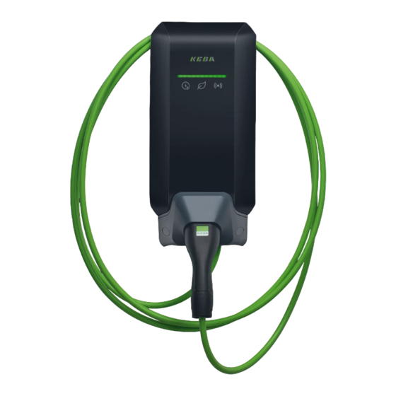
Description of the charging station P40 / P40 Pro Description of the charging station Front view KeContact P40 ... Housing cover ... LED bar (status display) ... Touch button ... Smart charging symbol ... RFID reader ... Charging plug with charging cable ... - Page 13 The plug holder for the charging cable can be installed directly beneath or separately from the charging station. Information If the plug holder for the charging cable is installed directly beneath the charging station, it can be used to secure the housing cover. Installation manual V1.01 © KEBA 2024...
-
Page 14: Rear View
... Flush-mounted cable opening (for ... Off-center substitute hole position control lines) View from below ... Surface-mounted cable opening (for ... Surface-mounted cable opening (for supply line) control lines) ... Fixed-mounted charging cable Installation manual V1.01 © KEBA 2024... -
Page 15: Type Plates
... Electrical data ... ClimatePartner certification ... CE marking ... Manufacturer address ... Operator information ... UKCA marking/address ... Country of manufacture ... Production location and date ... Serial number as a QR code Installation manual V1.01 © KEBA 2024... -
Page 16: Product Key (Variants Of The Charging Station)
...Cable variant, no cable attached Cable 6 …Cable lenght in meter [m] (0 = no cable) ...1 phase Phases ...3 phases ...3 phases→1 phase (phase switching) ...16 A VIII Maximum Charging Current ...32 A Installation manual V1.01 © KEBA 2024... - Page 17 ...Variant 1 ...not equipped Touch button ...Touch button XXII User interface L ...LED XXIII Future options 0 ...None Options for individual customer versions, not relevant for EU XXIV Customer options xxxx declaration of conformity Installation manual V1.01 © KEBA 2024...
-
Page 18: Status Displays
Indicates that the LED bar pulses at a consistent speed. Example The light pattern explanations are shown in a short time sequence for a duration of 5 sec- onds. The example shows that the entire LED bar flashes green for 0.5 seconds every 5 seconds. Installation manual V1.01 © KEBA 2024... - Page 19 The charging process is blocked by the charging sta- tion (e.g. vehicle not ready, switch contact input or load management specification). KEBA eMobility App can be used to start identification of the charging station. The charging station emits a short Flashing green (one cycle) flashing signal and audio signal in order to be identified.
-
Page 20: Displays In Event Of Error
Installation mode was ended using the Service key and settings have been saved. Flashing orange (2x short) The ampere values shown in the illustrations are printed on the housing of the charging station. Installation manual V1.01 © KEBA 2024... -
Page 21: Optional Operating Elements
In this case, the charging current limit can be waived once for the current charging session using the touch but- ton (1) (contact surface), if this is permitted by the grid operator. This charges the vehicle faster, if needed. Installation manual V1.01 © KEBA 2024... -
Page 22: Smart Charging Symbol
(e.g. due to a network problem). The animation follows the display on the light bar. Orange The charging station is in a critical error state. The animation follows the display on the light bar. Installation manual V1.01 © KEBA 2024... -
Page 23: Power Supply And Line Dimensioning
The rated current must be determined in accordance with the type plate data in coordination with the desired charging power and the supply line. Installation manual V1.01 © KEBA 2024... - Page 24 The charging station is set to 16 A in the delivery state. To adjust the maxi- mum current to the installed circuit breaker, the charging current must be configured using the Service key or using KEBA eMobility App. Installation manual V1.01...
-
Page 25: Mounting And Installation Instructions
● The mounting surface must be level and completely cover the back side of the charging station. ● Choose a suitable tightening torque for the mounting screws that is ap- propriate for the subsurface; however, the tightening torque must not ex- ceed 7 Nm. Installation manual V1.01 © KEBA 2024... -
Page 26: General Criteria For The Site Selection
The charging station must not be exposed to direct spray water (e.g. neighboring manual car wash facility, high-pressure cleaner, garden hose). ● The charging station should be protected against direct rain as far as possible to prevent icing, hail damage or similar. Installation manual V1.01 © KEBA 2024... -
Page 27: Required Tools
Installation specifications and space requirement Installation specifications The charging station must be installed vertically, without any tilt, on a wall or floor-mounted column. Installation on the floor or on a ceiling is not permit- ted. Installation manual V1.01 © KEBA 2024... - Page 28 ● For a device variant with an energy meter, a larger clearance on the right side is recommended to allow for the display to be read comfort- ably. Installation manual V1.01 © KEBA 2024...
-
Page 29: Preparing The Charging Station For Installation
2) Lift the housing cover at the bottom, then re- move it upward. 1) Remove the four Torx screws (1) of the pro- tective cover. 1) Lift the protective cover (1) at the bottom (2), then remove it upward. Installation manual V1.01 © KEBA 2024... - Page 30 Tool size: 34 mm 1) For the use of cable glands, the correspond- ing seals must be cut out of the charging station in a ring shape. 2) Ensure leak-tightness when inserting the ca- ble gland. Installation manual V1.01 © KEBA 2024...
-
Page 31: Mounting The Charging Station
Preparing the charging station for installation"). Hole positions ... Charging station mounting holes ... Plug holder mounting holes ... Flush-mounted cable routing (op- ... Upper substitute hole position tional) (marked on the back side of the charging station) Installation manual V1.01 © KEBA 2024... - Page 32 8) In case of surface-mounted cable routing, maintain a sufficiently large bending radius so that the plug holder under the charging station does not collide with the connection cables. Installation manual V1.01 © KEBA 2024...
-
Page 33: Notes On Cable Routing
● Examine all cable passages for tightness. Any optional cable glands used must be properly installed and screwed sufficiently tightly, as other- wise water ingress can occur. Installation manual V1.01 © KEBA 2024... -
Page 34: Electrical Connections And Wiring
Voltage zones ... Protective extra-low voltage zone ... Low-voltage zone All control lines must be routed in the protective extra-low voltage zone, safely separated from the connection lines of the low-voltage zones. Installation manual V1.01 © KEBA 2024... -
Page 35: Connecting The Voltage Supply
The supply terminals are designed as push-in spring terminals. 9.3.1 Connection example - Cable entry from below 1-phase: Via terminals 3-phase: Via terminals L1, N and L1, L2, L3, N and 1… Cable sheathing 2…Installation pipe (fixed routing) Installation manual V1.01 © KEBA 2024... - Page 36 4) Push all connector wires into the designated terminal openings of the push-in spring terminals as far as they will go. 5) Check that all connector wires are positioned securely. The charging station is connected to the power supply. Installation manual V1.01 © KEBA 2024...
-
Page 37: Electrical Connection To Special Systems Of Ac Power Supply
A three-phase con- nection in delta networks should only take place with an upstream trans- former ("triangle-to-star converter"). Fig. 9-2: Connection to a three-wire IT system with 230 V Installation manual V1.01 © KEBA 2024... -
Page 38: Connection Overview Of The Application Module
Only SELV/PELV voltages and circuits that have a safe separation from hazardous voltages (for example, sufficient insulation) are permitted to be connected to terminals [X1] through [X4] (switch contact inputs, switch con- tact output, LAN port and RS485 port). Installation manual V1.01 © KEBA 2024... -
Page 39: Switch Contact Inputs [X1A] / [X1B]
To read in the state, the external switch contact is loaded with 12 V DC PELV voltage and 2 mA. The terminals are designed as push-in spring terminals. Activation and configuration of this function takes place using KEBA eMobil- ity App. Connection diagram (example of X1a) ... - Page 40 Charging enabled when X1x is closed AND RFID authorization is correct. X1x function "Authorization bypass": Charging enabled when X1x is closed OR RFID authorization is correct. On…Function activated in the app / Off…Function deactivated in the app Installation manual V1.01 © KEBA 2024...
-
Page 41: Switch Contact Output [X2]
The switch contact output for SELV/PELV voltages has 1500 V AC isolation from the internal electronics. The terminals are designed as push-in spring terminals. Activation and configuration of this function takes place using KEBA eMobil- ity App. WARNING! Risk of electric shock! Supply the terminal for the switching contact output [X2] exclusively from a voltage source that has SELV/PELV protective extra-low voltage. - Page 42 Main relay monitoring signal- X2 switch contact output function The charging station then behaves as follows: Switch contact output [X2] State Open No error. Error - The switch contacts of the installed Closed main relay are stuck. Installation manual V1.01 © KEBA 2024...
- Page 43 The switch contact output can also be used to de-energize the charging sta- tion with a higher-level disconnect solution in the event of error. Activation and configuration of this function takes place using KEBA eMobil- ity App. Connection diagram ...
-
Page 44: Network Connection (Lan) [X3]
The network connection establishes a wired connection to an Ethernet net- work (LAN). The floating network connection is executed as a RJ45 socket. Activation and configuration of this function takes place using KEBA eMobil- ity App. WARNING! Risk of electric shock! In extended systems, a transient current flowing through the shielding can lead to hazards when work is being done on the data lines. - Page 45 The "Link/Act" status LED for the network interface is located above the RJ45 socket. "Link/Act" status LED Description No connection to the network Lights up green Connection to the network (Link) Flashes green Data transfer in progress (Activity) Installation manual V1.01 © KEBA 2024...
-
Page 46: Rs485 Interface* [X4] (For External Energy Meter)
For details on integrating external energy meters, refer to the chapter "14.1 Integration of an external energy meter." Activation and configuration of this function takes place using KEBA eMobil- ity App. The terminal is designed as a push-in spring terminal. Bus cabling requirements ●... - Page 47 The excess length of the bus cable must be routed in the center in the designated area so that safe separation from the supply line and charg- ing cable is guaranteed. The bus cable is connected. Installation manual V1.01 © KEBA 2024...
-
Page 48: Switching On The Power Supply
The power supply can be switched on after successful connection of all nec- essary lines. 1) Position the protective covers for commissioning the charging station. 2) Switch on the corresponding cut-off device for the power supply in the upstream electrical installation. Installation manual V1.01 © KEBA 2024... -
Page 49: Wireless Connections
WLAN connection The WLAN module establishes a wireless connection to a local network (LAN). Activation and configuration of this function takes place using KEBA eMobil- ity App. Ensure a connection of sufficient quality to your WLAN access point to guar- antee a reliable connection. - Page 50 The SIM card can also be removed in the switched-on operating state. 1) By lightly pressing the SIM card with your finger, the mechanism is acti- vated and the SIM card is ejected. 2) Remove the SIM card upward. Installation manual V1.01 © KEBA 2024...
-
Page 51: Configuration
Basic electrical configuration and parameterization using the After the device has been connected with KEBA eMobility App and put in in- stallation mode, the charging current limit and other settings can be parame- terized according to the local connection requirements using the "Installer"... -
Page 52: Activating/Deactivating Installation Mode
Installation mode is activated. Simplified configuration of the charging cur- rent limit using the Service key or extended configuration of the charging sta- tion using KEBA eMobility App can now be performed. Deactivating installation mode Installation mode can be ended as follows: ●... -
Page 53: Basic Electrical Configuration Directly At The Device
6A, 8A, 10A, 16A, 20A or 32A. An LED lights up beneath the set charging current limit. If a custom value was set for the charging current limit using KEBA eMobility App, the LED for […] lights up. -
Page 54: Establishing An App Connection Via Bluetooth
P40 / P40 Pro 11.3 Establishing an app connection via Bluetooth® For the initial use of KEBA eMobility App and for configuring or operating the charging station, proceed as follows: 1) Install KEBA eMobility App on your mobile device. ®... - Page 55 Switches the output if stuck main relay con- signaling tacts are detected and the internal main re- lay can no longer be actuated. Deactivating installation mode 1) Deactivate installation mode (see "11.1 Activating/deactivating installa- tion mode"). Installation manual V1.01 © KEBA 2024...
-
Page 56: Operation And Extended Configuration Using The App
P40 / P40 Pro 11.5 Operation and extended configuration using the app Using KEBA eMobility App, the "User" role can be selected to perform ex- tended configuration. To do this, proceed as follows: 1) Select the charging station in KEBA eMobility App (see "11.3 Establish-... -
Page 57: Activating/Deactivating Bluetooth
LED is dark under the corresponding display. Deactivating Bluetooth® The Bluetooth® function integrated into the charging station is activated by default and can be deactivated as needed using KEBA eMobility App. 1) Navigate to the "Settings" in the app and follow the corresponding menu items. -
Page 58: Displays During Configuration
Installation mode was ended using the Service key and settings have been saved. Flashing orange (2x short) The ampere values shown in the illustrations are printed on the housing of the charging sta- tion. Installation manual V1.01 © KEBA 2024... -
Page 59: Commissioning
● State-of-the-art testing devices allow for measurement of the loop im- pedance without triggering a fault current device. This enables the mea- surement to take place using a vehicle simulator in the charging state. Installation manual V1.01 © KEBA 2024... -
Page 60: Mounting Covers / Sealing
A missing terminal cover can cause an electrical hazard in event of error (conductor has come loose from the terminal)! ● Always attach the terminal cover to guarantee safe separation between hazardous voltages and touchable voltages. Installation manual V1.01 © KEBA 2024... - Page 61 The housing cover must be correctly seated in the housing guide on all sides and snap in on the left and right in the lower area (3). The housing cover is fitted. Installation manual V1.01 © KEBA 2024...
-
Page 62: Mounting The Plug Holder
2) Insert the two covering caps into the open- ings of the plug holder. The plug holder is mounted. Installation manual V1.01 © KEBA 2024... -
Page 63: Rfid Authorization
For a charging station without a higher-level OCPP backend, all RFID cards must be taught in and saved locally at the charging station. Up to 1000 RFID cards can be stored. RFID cards are managed using KEBA eMobility App or via the optional KEBA eMobility Portal. Management through the OCPP backend If the charging station is connected to a higher-level OCPP backend, RFID cards are managed using the OCPP backend. - Page 64 "Authorization with/without OCPP back- end (no connection)" applies. Standard: Offline local authorization Information The setting from the table "Authorization with OCPP backend (with connec- tion)" is not taken into account. Installation manual V1.01 © KEBA 2024...
-
Page 65: Special Functions
... Optional PV system Information The illustration provides an example system overview and does not include all the necessary auxiliary devices required for safe operation of the system (e.g. line circuit breaker, residual current device, etc.). Installation manual V1.01 © KEBA 2024... -
Page 66: Connection Of An External Energy Meter (Modbus Tcp)
The RS485 interface (Modbus-compatible) of the charging station is deacti- vated by default. If an external energy meter (Modbus RTU) is installed in the system, this interface must be configured. Activation and configuration of this function takes place using KEBA eMobil- ity App. Installation manual V1.01... -
Page 67: Supported External Energy Meters
A9MEM3155 3+N / 63 A Hager ECR180D 1+N / 80 A Hager ECR380D 3+N / 80 A These 3-phase energy meters are suitable for the "Dynamic domestic connection monitor- ing" and "PV-optimized charging" functions. Installation manual V1.01 © KEBA 2024... -
Page 68: Dynamic Domestic Connection Monitoring
This function can extend the charging time of the vehicle. Temporary deacti- vation of this function (charging boost) is not possible, as this could overload the domestic connection. Activation and configuration of this function takes place using KEBA eMobil- ity App. Requirements ●... -
Page 69: Pv-Optimized Charging
This function can extend the charging time of the vehicle. This function can be temporarily deactivated (charging boost) using KEBA eMobility App, the touch button (depending on the variant) or a switch contact input. Activation and configuration of this function takes place using KEBA eMobil- ity App. Prerequisite ●... - Page 70 If the minimum charging current for all 3 3p.→1p. phases cannot be provided any longer → available charging capacity < 4.14 kW. If the minimum charging current on all 3 1p.→3p. phases can be provided again → available charging capacity > 4.14 kW. Installation manual V1.01 © KEBA 2024...
-
Page 71: Remote Control By The Power Grid Operator
This is used to limit the electricity volume of devices with high consumption during peak usage times in the power grid. Activation and configuration of this function takes place using KEBA eMobil- ity App. Regulation principle A corresponding switching signal for power limiting by the grid operator must be connected to a switch contact input [X1]. -
Page 72: Ocpp Backend
The selected port must be con- figured on the charging station. Access to external (outgo- Port at which the OCPP backend Custom ing) can be reached. Port for optional connection with an Incoming and outgoing NTP server (time server). Installation manual V1.01 © KEBA 2024... - Page 73 OCPP backend Supported OCPP messages Message Authorize BootNotification ChangeAvailability ChangeConfiguration ClearCache DataTransfer GetConfiguration Heartbeat MeterValues RemoteStartTransaction RemoteStopTransaction Reset StartTransaction StatusNotification StopTransaction UnlockConnector GetDiagnostics DiagnosticsStatusNotification FirmwareStatusNotification UpdateFirmware GetLocalListVersion SendLocalList CancelReservation ReserveNow ClearChargingProfile GetCompositeSchedule SetChargingProfile TriggerMessage Installation manual V1.01 © KEBA 2024...
-
Page 74: Short Description Of The App
Short description of the app P40 / P40 Pro Short description of the app KEBA eMobility App is an extended user interface for the charging station and can be used for the following applications: ● View the current status. ●... - Page 75 Possible settings are: LAN, WLAN, User mode WLAN hotspot ● Start and stop charging processes ● Comprehensive configuration options (interfaces) ● RFID card management ● And much more Installation manual V1.01 © KEBA 2024...
-
Page 76: Establishing An App Connection Via Bluetooth
P40 / P40 Pro 16.1 Establishing an app connection via Bluetooth® For the initial use of KEBA eMobility App and for configuring or operating the charging station, proceed as follows: 1) Install KEBA eMobility App on your mobile device. ®... -
Page 77: Establishing An App Connection Via Lan/Wlan
To use the app, proceed as follows: 1) Start KEBA eMobility App and establish the connection to the charging station. Re-entering the PIN is not necessary. The connection to the charging station is established. -
Page 78: Maintenance
Software update with KEBA eMobility App To update the software of the charging station, proceed as follows: 1) Open KEBA eMobility App and connect with the charging station. 2) A more recent software version is shown in the app. The update process can be started directly from there. -
Page 79: Troubleshooting
WLAN connection Software update via KEBA eMobility Portal If the charging station is registered in KEBA eMobility Portal and connected with it, a software update can be initiated conveniently through the portal. In the portal, the RAUC update method can also be selected, for example. -
Page 80: Accessories
Accessories P40 / P40 Pro Accessories 18.1 Floor-mounted columns KeContact P40 is suitable for installation on the following floor-mounted col- umns. V1: #131 771 The floor-mounted column is suitable for the installation of one charging station. V2: #131 813 The floor-mounted column is suitable for the installation of two charging stations on it. -
Page 81: Disposal
The materials are recyclable in accordance with their labeling. You can make an important contribution to protecting our environment by reusing, renewing and recycling materials and old appliances. Sustainability Please consider the environment. The device contains valuable raw materi- als which should be recycled. Installation manual V1.01 © KEBA 2024... -
Page 82: Technical Data
Depending on the cable and the type of in- Connection cross-section of the supply: stallation ● 16 A nominal current: 2,5-10 mm / AWG 13-7 ● 32 A nominal current: 6,0-10 mm / AWG 9-7 Stripping length: 18 mm Maximum terminal temperature: 90 °C Installation manual V1.01 © KEBA 2024... -
Page 83: Ambient Conditions
Isolation voltage 1500 V AC (1 min.) ® Bluetooth ® Bluetooth standard: BLE 5.0 or higher Intended use: Connection with KEBA eMobility App Band: 2,4 GHz Switch contact inputs [X1a / X1b] Connections for external, potential-free Type: switch contacts Quantity: Authorization, charging current reduction,... - Page 84 Flexible conductor with wire end ferrule: max. 0,75 mm² / AWG 19 Stripping length: 10 mm PLC (Power Line Communication)* // only KeContact P40 Pro Communication with the vehicle: ISO 15118 ready* … Function will be made available with a later software update.
-
Page 85: Equipment Depends On Version
Time delay in the event of a fault current: Type for general use Mounting method: Installation type Connections are independent of the mechan- Method of connection: ical mounting Type of terminals: Screwless terminals for external copper wires Installation manual V1.01 © KEBA 2024... - Page 86 Rated current: = 32 A Rated DC residual operating current: = 0.006 A Δdc Rated making and breaking capacity: = 500 A Rated conditional short-circuit current: = 3000 A Degree of protection: IP 10 Installation manual V1.01 © KEBA 2024...
-
Page 87: Dimensions And Weight
476 mm / 221 mm / 142 mm Weight of the charging station (including 6m ~ 6,2 kg (depending on variant) charging cable): Dimensions of the packaging: 590 mm x 280 mm x 258 mm Installation manual V1.01 © KEBA 2024... -
Page 88: Eu Directives And Standards
2014/53/EU Radio Equipment Directive (RED) Directive on the restriction of the use of cer- 2011/65/EU tain hazardous substances (RoHS) Directive for waste electrical and electronic 2012/19/EU equipment (WEEE) 2014/32/EU European Measuring Device Directive (MID) Installation manual V1.01 © KEBA 2024... -
Page 89: Index
Connecting the voltage supply .... 35 Display information...... 18 Connection diagram X1x ...... 39 Error states.......... 20 Connection diagram X2 ...... 41 Line circuit breaker........ 23 Connection overview Location selection ........ 26 Application module ...... 38 Cut-off device .......... 23 Installation manual V1.01 © KEBA 2024... - Page 90 PV-optimized charging ...... 69 Space requirement........ 28 Supported RTU energy meters .... 67 Supported TCP energy meters .... 67 Switch contact inputs ....... 39 Switch contact output....... 41 Disconnect solution connection example ............ 43 Switching on the power supply .... 48 Installation manual V1.01 © KEBA 2024...
- Page 91 Tool ........... 27, 34 WLAN connection ........ 49 Touch button ........... 21 Troubleshooting........ 79 X1a............ 39 Type plates X1b............ 39 Charging station........ 15 X2............. 41 Position .......... 15 X3............. 44 X4............. 46 View from below ........ 14 Voltage zones.......... 34 Installation manual V1.01 © KEBA 2024...
- Page 92 Index P40 / P40 Pro Installation manual V1.01 © KEBA 2024...
- Page 94 KEBA Energy Automation GmbH Reindlstraße 51 4040 Linz / Austria www.keba.com...
Need help?
Do you have a question about the KeContact P40 and is the answer not in the manual?
Questions and answers