Table of Contents
Advertisement
Quick Links
Advertisement
Table of Contents

Related Manuals for Dormakaba DB25


Summary of Contents for Dormakaba DB25
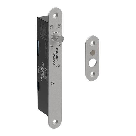
- Page 1 Solenoid Drop Bolt DB25 Operating Manual WN 060423 45532/16458 - 08/2022...
-
Page 2: Table Of Contents
Example 2: Install lock on frame and strike plate on glass door. Electrical connection Select power supply Connections Three-wire connection (recommended) Two-wire connection Connect signaling contacts for door position and bolt position. Configure lock Maintenance and Cleaning Disposal of the device Solenoid Drop Bolt DB25 WN 060423 45532/16458 - 08/2022... -
Page 3: Information About This Document
1 Information about this document 1.1 Contents and purpose This manual describes installation, connection, operation and maintenance of the lock DB25. Read the manual carefully and observe the instructions it contains. They contain important information for reliable installation and trouble-free operation. -
Page 4: Security
In case of non-professional assembly or connection, serious injuries, fire or material damage may result from the system. • Assembly and connection may only be carried out by persons who have the re- quired qualifications. Solenoid Drop Bolt DB25 WN 060423 45532/16458 - 08/2022... -
Page 5: Product Description
Screws M5 × 10 3.2 Accessories (to be ordered separately) • Short striking plate DBA103A 2400001213 • Long striking plate DBA103E 2400001214 • Housing DBA104J 2400001215 • Cover plate DBA106J 2400001216 WN 060423 45532/16458 - 08/2022 Solenoid Drop Bolt DB25... -
Page 6: Variants
Electrical connection Connection terminals Screw terminals Conductor cross-section 0,20 ... 2.0 mm²/AWG24 ... AWG14 Signal contacts Latch position max. 25 V DC max. 500 mA Door position max. 100 V DC max. 500 mA Solenoid Drop Bolt DB25 WN 060423 45532/16458 - 08/2022... -
Page 7: Dimensions
Ø15,5 12,5 12,5 Ø5,5 Ø10 12,5 12,5 2× M5×0,8 Fig. 2: Lock - dimensions Dimensions lock Dimensions housing (accessories) Dimensions short striking plate Dimensions cover plate (accessories) Dimensions long striking plate (accessories) WN 060423 45532/16458 - 08/2022 Solenoid Drop Bolt DB25... -
Page 8: Operating Modes And Functions
Operating modes and functions Operating Manual 4 Operating modes and functions 4.1 Overview of functions The DB25 is a magnetically operated deadbolt lock for single-closing doors. The intelligent electronics provide a range of functions: Features • Multi-voltage input (DC 12 V/24 V) •... - Page 9 Operating Manual Operating modes and functions Functional overview of lock and connection variants DB25 Connection Multiple relocking Automatic. Re- Time for relocking Multiple locking adjustable unlocking Lock variant: Fail-safe (currentless opening) Three-wire yes (9×) connection Two-wire connection yes (5×) Lock variant: Fail-secure (currentless closing) Three-wire yes (5×)
-
Page 10: Mounting
6 mm. If the gap is greater, the lock can no longer correctly detect the position of the striking plate and will no longer function reliably. Installation position The lock can be mounted horizontally or vertically. Solenoid Drop Bolt DB25 WN 060423 45532/16458 - 08/2022... - Page 11 48 m 0,52 26 m 77 m 0,82 41 m 122 m 1,31 65 m 195 m 2,08 103 m 310 m Table 2: Conductor cross-section as a function of the cable length WN 060423 45532/16458 - 08/2022 Solenoid Drop Bolt DB25...
-
Page 12: Example 1: Installing Lock And Strike Plate In Mortise Openings
8. Install the strike plate into the door panel and secure with two 10G×1" screws. 9. Check the alignment of the lock and strike plate with each other. The striker must be able to enter the strike plate freely. Solenoid Drop Bolt DB25 WN 060423 45532/16458 - 08/2022... -
Page 13: Example 2: Install Lock On Frame And Strike Plate On Glass Door
The magnet function should catch and align the door so that the striker bolt can freely retract into the strike plate. When the housing is in the correct position, press the housing firmly into place. WN 060423 45532/16458 - 08/2022 Solenoid Drop Bolt DB25... -
Page 14: Electrical Connection
In this case, additional wire jumpers are required. Terminals 4 to 8 are signaling contacts which can be evaluated by an access control or alarm system. Solenoid Drop Bolt DB25 WN 060423 45532/16458 - 08/2022... -
Page 15: Three-Wire Connection (Recommended)
8 7 6 5 4 3 -ve CL NC NO C The DIP switches are already correctly configured at delivery and do not need to be changed. Power 12-24VDC WN 060423 45532/16458 - 08/2022 Solenoid Drop Bolt DB25... -
Page 16: Connect Signaling Contacts For Door Position And Bolt Position
Table 5: Switch positions S1 and S2 Connection M position Lock variant fail-safe (currentless opening) Three-wire connection Off (default) Two-wire connection Lock variant fail-secure (currentless closing) Three-wire connection On (default) Two-wire connection Table 6: Switch positions M Solenoid Drop Bolt DB25 WN 060423 45532/16458 - 08/2022... -
Page 17: Maintenance And Cleaning
• Play of the latch • Contamination • Escaping lubricant • Moisture If there are unusual noises, noticeable play, escaping lubricant or similar, replace the lock. Table 7: Maintaining and cleaning the lock WN 060423 45532/16458 - 08/2022 Solenoid Drop Bolt DB25... -
Page 18: Disposal Of The Device
• Germany dormakaba Deutschland GmbH will properly dispose of goods delivered at the end of their useful life, in accordance with the legal regulations (ElektroG or the Electrical and Electronic Equipment Act in Germany). Any transport costs incurred are to be borne by the owner of the electronic device. - Page 19 Operating Manual Notes WN 060423 45532/16458 - 08/2022 Solenoid Drop Bolt DB25...
- Page 20 Deutschland GmbH DORMA Platz 1 58256 Ennepetal Germany Headquarters: +49 2333 793-0 Service DE: 0800 524 0246 www.dormakaba.com www.dormakaba.com...
Need help?
Do you have a question about the DB25 and is the answer not in the manual?
Questions and answers