Table of Contents
Advertisement
Quick Links
Advertisement
Table of Contents
Troubleshooting

Related Manuals for Varmebaronen MP4 G3


Summary of Contents for Varmebaronen MP4 G3
- Page 1 MANUAL Use and Installation Mini Boiler MP4 G3 and MP6 G3...
-
Page 2: Table Of Contents
Contents About the manual…….……………………………………………………………………………………………………………………………..2 1.1. About the User Manual ............................2 1.2. About the Installation Manual ........................... 2 1.3. Explanation of symbols ............................2 1.4. Disclaimer ..................................2 User Manual………………………………………………………………………………………………………………………………………………3 2.1. Safety ....................................3 2.2. Installation information ............................4 2.3. Overview.................................... -
Page 3: About The Manual
1. About the manual This manual consists of two parts, a User Manual and an Installation Manual. 1.1. About the User Manual The User Manual is aimed at those who have purchased a boiler made by Värmebaronen. Here you will find descriptions of boiler functions, user instructions and maintenance advice. -
Page 4: User Manual
2. User Manual 2.1. Safety • Please read through the User Manual carefully before using the boiler! • Installation, service and other measures may only be carried out by a qualified installation engineer. However, normal users are allowed to perform the maintenance that is described on pages 13-16. •... -
Page 5: Installation Information
Does the system contain anti-freeze? Type of glycol: Concentration in %: Note! Max. 30%. Electrical connection MP4 G3 1.5 kW / 230 V ~ MP6 G3 2 kW / 230 V ~ 2.25 kW / 400 V 2N ~ 3 kW / 400 V 2N ~... -
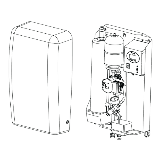
Page 6: Overview
2.3. Overview... - Page 7 Control panel 2. Power switch 3. Overheating protection 4. Vent valve 5. Safety valve 6. Pressure gauge 7. Drain water tank 8. Expansion tank 9. Circulation pump 10. Boiler tank and immersion heater 11. Design label 12. Touch protection, boiler electronics 13.
- Page 8 Bypass valve (14) Using the bypass valve, the installation engineer can shut off the circulation in the pipe system. The bypass valve can also act as a safety feature that allows circulation inside the boiler in the event of a blockage in the pipe system.
-
Page 9: Functions And Settings
Safety valve (5) The safety valve opens and releases water if the boiler’s water pressure exceeds 2.5 bar. The water is collected in the drain water tank. The safety valve closes automatically when the water pressure drops below approx. 2 bar. Pressure gauge (6) The pressure gauge shows the water pressure in the boiler. -
Page 10: Eco Function
3. Select icon Heating curve Current temperatures Installation engineer settings Alarms, warnings, limitations and log list ECO function Time and date Language selection Product information 4. Use the arrows to navigate the submenus. 5. Use the plus and minus buttons to change the setting. 6. -
Page 11: Temperature-Regulating Functions
Activating and deactivating the ECO function 1. Press the menu button. 2. Use the arrows to navigate the menu. 3. Select the ECO function symbol. 4. Use the plus and minus buttons to switch between NORM and ECO. To activate the ECO function, select ECO. To deactivate the ECO function, select NORM. -
Page 12: Safety Functions
If you are unhappy with the indoor temperature after adjusting the heating curve level, you can also adjust the heating curve’s slope. Adjust the heating curve slope 1. Press the menu button. 2. The heating curve is selected. 3. Press the Confirm button. 4. -
Page 13: Alarms, Warnings And Limitations
Reset the overheating protection Wait until the boiler has cooled down to 65°C or a lower temperature. 2. Loosen the rubber cover in the hole for resetting. 3. Using a screwdriver, push firmly inwards into the hole until you hear a click. 4. -
Page 14: Maintenance
Warnings The boiler will start up again if the reason for the warning ceases, but the warning will remain on the display until you have acknowledged the warning. When a warning has been activated, the boiler will perform the following actions: The boiler temporarily stops operating. - Page 15 Check the vent valve Unscrew the red plastic cap. Check for deposits or water leaks by the vent valve. If these are present, contact your installation engineer for troubleshooting and remedial actions. Screw on the red plastic cap. Check the safety valve’s opening function Note! This check must be performed quickly so that the system does not lose too much water and pressure.
- Page 16 Check the water pressure Check the water pressure while the boiler is cold. Refer to the installation engineer’s note regarding the set pre-charge pressure on page 4. If the pressure is less than 0.2 bar above the pre-charge pressure, add water to the pipe system via the filling valve. If the filling valve is missing, contact your installation engineer.
-
Page 17: Troubleshooting
2.6. Troubleshooting Notify any error code when you contact your installation engineer. What has happened? What does it mean? What should I do? A warning signal sounds. The boiler has activated Turn off the alarm signal by acknowledging the an alarm. alarm: Press the button furthest to the left. - Page 18 What has happened? What does it mean? What should I do? The boiler has triggered The boiler temperature Reset the overheating protection or contact your the overheating has exceeded 80°C and installation engineer. protection, the red light the boiler has shut down. Read how to reset the overheating protection is flashing and the on page 12.
-
Page 19: Installation Manual
3. Installation Manual 3.1. Safety • The boiler must not be used for direct heating of drinking water. • The boiler may only be installed indoors. • In cases where the instructions in this manual violate national regulations, the latter must be followed. •... -
Page 20: Install The Boiler And The Outdoor Sensor
Recommended water values Subject Recommended value Risk in the event of deviating value pH value Between 7.5 pH and 8.5 pH Lower values can result in corrosion damag Alkalinity At least 60 mg/l Corrosion. Carbonic acid content Max. 25 mg/l Corrosion. -
Page 21: Fill With Water And Adjust The Pressure
Adapt the size of the pipe system The built-in expansion tank in the boiler is dimensioned to fit most normal installations, but may need to be expanded. The size of heating system that the boiler’s expansion tank can cope with is affected by the volume of liquid in the system, the operation and static pressure of the heating system, as well as the max. - Page 22 The pre-charge pressure in the expansion tank should be approx. 0.1 bar higher than the system’s static pressure, and the minimum operating pressure should be 0.2 bar higher than the static pressure so that there is always a little water left in the expansion tank. Adjust the operating pressure in the system When the boiler is being filled with cold water, the operating pressure must be set to the lowest desired pressure;...
-
Page 23: Install The Electricity
3.2.6. Install the electricity Electrical installation or alteration to electrical installation may only be carried out by qualified personnel. Overview Connection, external blocking / alternative Terminal block temperature Jumper (option) Level sensor for water level sensor Circulation pump Room unit connection Overheating protection Potential-free relay output for buzzer alarm Control switch... - Page 24 Wiring diagram Electrical installation or alteration to electrical installation may only be carried out by qualified personnel. For an explanation of labels, see page 22. Jumper N – X option for single-phase coupling and for increasing the power in the case of two-phase coupling. The jumper is not included in the boiler delivery...
- Page 25 Connect the boiler Depending on the design of the electrical system and the pipe system, connect the boiler to: • One phase with jumper • Two phases without jumper • Two phases with jumper • Three phases One phase with jumper MP4: 1.5 kW / 230 V~ / 6.5 A MP6: 2.0 kW / 230 V~ / 8.7 A Power cable:...
-
Page 26: Venting The Boiler
3.2.7. Venting the boiler Unscrew the red cap on the vent valve to vent the boiler. Don’t forget to refit the red cap to ensure that the vent valve works automatically. The float switch temporarily turns off the boiler and triggers a warning if the vent valve is unable to vent the boiler automatically. - Page 27 Menu overview...
- Page 28 Menu functions On the display Explanation Enable UTK Select YES to activate the outdoor sensor and NO to deactivate the outdoor sensor. (Installation engineer settings) Current temperatures Displays current temperatures for Boiler temperature, Setpoint, Outdoor temperature, Room temperature, (Main menu) Room setpoint and Internal temperature.
- Page 29 On the display Explanation Contrast Adjusts the display’s contrast. The factory setting is 10. (Installation engineer Selectable values range from 10 to 34. The setting should not settings/ Advanced) be changed. Curve slope The curve slope regulates how much the flow temperature (Heating curve) increases in relation to the outdoor temperature.
- Page 30 On the display Explanation Summer mode The summer mode specifies the outdoor temperature at which the boiler stops heating and activates the ECO function. (Heating curve) Selectable values range from 0 to 40°C. The factory setting is 17°C. Language selection Selectable languages are Swedish, Norwegian and English.
-
Page 31: After Installation
3.3. After installation 3.3.1. Registration Fill out the enclosed registration form. Post the copy with the pre-printed address to Värmebaronen and give the other copy to the user. 3.3.2. Installation engineer’s checklist Before starting up the boiler Has the electrical installation been adapted to the local power supply? Are the boiler and heating system filled with water and vented? Is the pressure correct? Are all pipe connections leakproof? -
Page 32: Troubleshooting
3.4. Troubleshooting Work on the system which requires tools, must only be carried out by authorised installation engineers! Ensure the boiler is disconnected from the power supply before starting work! Possible cause What has happened Control valves in the system are restricting the flow. No or insufficient heat. - Page 33 Troubleshooting outdoor sensor The outdoor sensor must not be connected to the circuit board during resistance measurement. Measurement points on the circuit board Values °C kΩ °C kΩ 88.7 64.2 47.0 34.7 25.9 19.5 14.8 Error codes Error code Explanation Alarm: The boiler’s temperature sensor is broken F01: Boiler sensor or the temperature cannot be measured.
-
Page 34: Technical Specification
When a value in the boiler reaches a set limit value and the boiler activates a limitation, the green indicator light flashes. When no limitations are activated, the green indicator light will be permanently lit. 3.5. Technical specification MP4 G3 and MP6 G3 700 mm Height 420 mm... - Page 35 Dimensional sketch Power options MP4 G3 Power options 1.5 kW 2.25 k 3.0 kW 4.5 kW Voltage 230 V 400 V 400 V 400 V Frequency 50/60 50/60 50/60 50/60 Current 6.5 A 5.6 A 7.5 A 6.5 A Fuse protectio...
- Page 36 Components Designation Quantity Art no Vent 245078 Circulation pump adapter cable for 246003 150017 Circulation pump Grundfos UPM3 AUTO 246003 L 15-50 130 (Alternative component) Circulation Pump Wilo Para 15/6-43/SC 246004 Immersion heater for MP4 G2: 4.5 kW 110010 Immersion heater for MP6 G2: 6 kW 110015 Immersion heater container 731392...
Need help?
Do you have a question about the MP4 G3 and is the answer not in the manual?
Questions and answers