
Subscribe to Our Youtube Channel
Related Manuals for Varmebaronen EP E Series


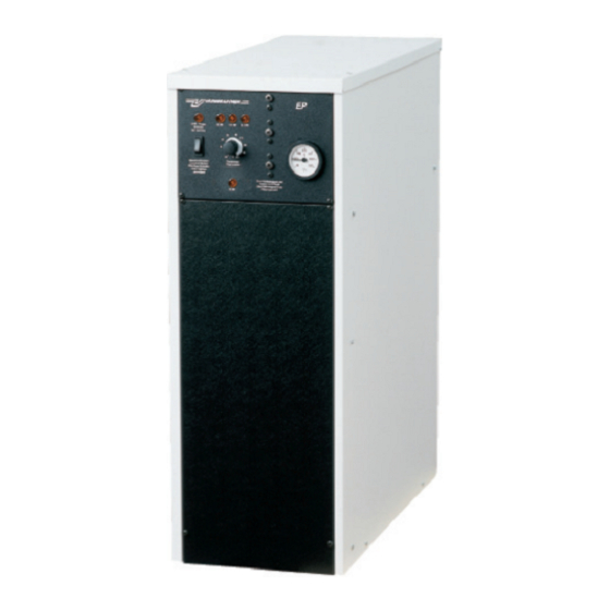
Summary of Contents for Varmebaronen EP E Series
- Page 1 Installation, operation and care EP E Series 7-stage electric boilers EP 26E EP 42E 2011-03-21 utg: xxxxxx Ersätter:08-05...
-
Page 2: Table Of Contents
Contents EP E series 11-03 General Electrical installation Notes Remote control/external block Features Remote control Technical data External block - external stage/power control HVAC installation External block Siting the boiler Passive 0-10 V Cables and pipework Active 0-10 V Safety/supply pipe... -
Page 3: Notes
Notes EP E series 11-03 To be completed when the boiler is installed! Type: EP 26 E EP 42 E Serial number: ............................Installation date: ............................Installer: ............................Tel: ............................Other: ...................................................................................................................................................................... Number of power stages: .............. -
Page 4: Features
Features EP E series 11-03 Heating or industrial processes Load guard The E Series contains two boilers with power ratings of 26.2 and 42 Load guard for power supply on 35- 125 A main fuse. Current trans- kW. The boilers can be used as the source of heat in water-based formers are included. -
Page 5: Technical Data
Technical data EP E series 11-03 EP 26 E EP 42 E Both models Power 26.25 Voltage 400V3N~, 50Hz Current 37.9 Cable fitting Ø 37 Power stage 3.75 Volume of water litre Current/stage Test pressure Connecting cable, max Operating pressure Max temperature °C... -
Page 6: Hvac Installation
HVAC installation EP E series 11-03 In large systems it is virtually impossible to prevent leaks and oxy- The installation must comply with the applicable genation. In such systems, an oxygen-demanding agent can be add- regulations and standards. ed so there is always a slight surplus in the system. These agents often contain anti-corrosive additives. -
Page 7: Hvac Installation
HVAC installation EP E series 11-03 Pressure drop diagram Closed expansion system <2.5 bar, <100 kW and <110 °C Pressure drop The safety and venting valves are mounted on the boiler safety pipe. Flow Direction of flow >2.5 bar, >100 kW and >110 °C... -
Page 8: Electrical Installation
Electrical installation EP E series 11-03 Circulation pump Electrical installation must be in accordance with the Connecting the circulation pump to the boiler allows you to utilise applicable regulations, under the supervision of an the pump stop function, which also operates the pump briefly authorised installer. when it is not in use. The function can be disabled for continuous operation. -
Page 9: Electrical Installation
Electrical installation EP E series 11-03 Remote control/external block External block Jumpers 2 - 3 removed. A PCB input has different functions depending on the position of SW Voltage-free contact to 2 -3. 4/1. The functions cannot be used at the same time. -
Page 10: Wiring Diagram - Ep 26 E
Wiring diagram - EP 26 E EP E series 11-03 1. Connection of supply cable, 12. Alarm, overheat protection triggered. 2. Circulation pump connection, 230V. 13. Alarm relay. 3. Current transformer. 14. Control switch. 4. Temperature sensor. 15. Control fuse. -
Page 11: Wiring Diagram - Ep 42 E
Wiring diagram - EP 42 E EP E series 11-03 11 10 1. Connection of supply cable, 13. Alarm relay. 2. Circulation pump connection, 230V. 14. Control switch. 3. Current transformer. 15. Control fuse. 4. Temperature sensor. 16. Overheat protection power groups one and two. -
Page 12: Electronic Control System - Settings
Electronic control system - settings EP E series 11-03 26. Button to temporarily disable delayed reconnection after power 6. Power/status light. failure and to speed up the connection of power stages. According to the standards, no more than 50% of the power can Steady glow: Normal operation. -
Page 13: Operation And Care
Control panel EP E series 11-03 6. Power/status light. 7. Temperature setting. 9. Indicator for power group one, approx. 15 % of power. 10. Indicator for power group two, approx. 30 % of power. 11. Indicator for power group three, approx. 55 % of power. -
Page 14: Troubleshooting
Troubleshooting EP E series 11-03 Any work requiring the use of tools must be carried out by an authorised electrical installer. Start all troubleshooting by looking at the status indicator, see point 6 on page 8. This section does not cover issues relating to the status indicator. -
Page 15: Components
Components EP E series 11-03 Ref. Product no. Name 26 E 42 E 16 00 20 Earth bar JS 35 923 03 Panel 16 01 05 Terminal 100-CT43 11 00 16 Immersion heater 6 kW 17 00 06 Relay 1-pole alt. - Page 16 Värmebaronen AB retains the right to change the specification of included components without prior notice, as part of its policy of continuous improvement and development. Värmebaronen AB �4644-226320 Arkelstorpsvägen 88 �4644-226358 291 94 Kristianstad www.varmebaronen.se Sweden info@varmebaronen.se...
Need help?
Do you have a question about the EP E Series and is the answer not in the manual?
Questions and answers