Advertisement
Quick Links
Quick Start Installation
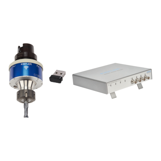
Rotating Cutting Dynamometer (RCD) and Wireless Receiver
Type 9170B...
Foreword
Thank you for choosing a Kistler quality product. Please read
these instructions carefully, so that you can take optimum
advantage of the versatile features of this product.
The information in this document is subject to change at any
time without prior notice. Kistler reserves the right to improve
and modify the product in accordance with technical progress
without the obligation to inform persons and organizations
based on these changes.
©2024 Kistler Group. All rights reserved.
Content
1. General information
2. Device description
3. Installation and commissioning
4. Restoring all settings
5. Service and support
6. Conformations
7. Safety instructions
1. General information
The complete measuring system 9170B comprises a
sensory tool holder (Rotating Cutting Dynamometer),
that can be mounted directly at the machine spindle and
a communication box 5347A (WL Receiver), that receives
the data through wireless from the tool holder. The spindle
type on the machine tool determines which rotor version
is required. The piezoelectric 4-component sensor, four
charge amplifiers and the digital transmission electronics are
integrated into the tool holder. It measures the radial forces
F
and F
, the axial force F
and the torque M
x
y
z
2. Device Description
The following brief description explains the basic components
of the measuring chain and refers to the corresponding
chapters with more detailed descriptions:
Tool holder (RCD) – 9170B...
1
Kistler Group
Eulachstraße 22
8408 Winterthur, Switzerland
Front side WL Receiver - 5374A...
Back side WL Receiver - 5374A...
5
6 7
Description
1
Overpressure valve
2
Magnetic charging plug
3
Analog outputs (BNC neg.)
Light-emitting diodes (LEDs), indicating
4
the status of the corresponding RCD input
(left side) or analog output (right side)
Main switch for the power supply of the
9170B_012-064e-01.24
5
device
6
Ground lug
Connector of the 24 V power supply
7
(e.g. plug-in power supply unit)
Remote control connector (D-Sub 9-pole neg.)
• Measure/Reset control (Pin 5)
8
• Start/Stop trigger (Pin 4)
• 24 V supply (Pin 1)
• GND (Pins 2 & 6)
USB ports for receiver dongle. The dongle
9
must be plugged into one of these ports.
2 Ethernet interfaces (RJ45). Only Sync In
10
connector active
Reset button for resetting the device to
11
factory settings
2.1 Overpressure valve
CAUTION
2.2 Charging the battery
The battery runtime (active measurement) is at least 5 hours.
Afterwards, the RCD with built-in battery can be charged via
the magnetic charging plug.
NOTE
.
z
2.3 Receiver dongle
The receiving antenna receives the data signals transmitted
by the tool holder (RCD) and forwards them to the WL
Receiver. The dongle should be placed as close as possible to
the RCD (range ≤5 m).
2.4 Status LEDs
The LEDs indicate the status of the corresponding RCD input
or analog output and the general operating statuses of the
device.
The table below shows the possible statuses:
LED status
2
no light
blue
blue
flashing
yellow
red
red
flashing
Tel. +41 52 224 11 11
info@kistler.com
4
4
3
8
9
10
Chapter
2.1
2.2
-
2.4
-
-
-
-
2.3
-
4
Do not discard old electronic instruments in
municipal trash. For disposal at end of life, please
return this product to an authorized local electronic
waste disposal service or contact the nearest Kistler
Instruments sales office for return instructions.
Only charge the RCD at an ambient temperature
between 0 and 40 °C. Use the original charger
and the original charging cables. Charging outside
the specifications can seriously and irreversibly
affect the performance and service life of the
rechargeable battery!
The receiver dongle is the receiving and
transmitting unit on the stationary side of the
measuring system. The receiver dongle contains
the transmitting and receiving antenna.
Operating status
RCD input LEDs
Output LEDs
No RCD connected, unit
-
switched off
RCD connected, battery ok,
Measurement
in progress
no overload
-
Reset
RCD connected,
-
battery <20%
RCD connected,Overload
Overload
RCD connected,
-
battery < 10%
www.kistler.com
3. Installation and commissioning
The tool holder (RCD) is a precision instrument that requires
careful handling. The following instructions should be
followed for that reason:
• The tool holder (RCD) has been fine balanced in order
for it to be able to be used for up to 16'000 rotations per
minute for force and moment measurements. Depending
on the selected adapter, there may be further restrictions
on the rotation speed. The binding permissible speed is
engraved on the housing of the RCD.
• Incorrect handling of the dynamometer has an immediate
influence on the balance quality and thus on the quality of
the measurement.
11
Do not allow the dynamometer to fall and do
not subject it to any hard blows! The maximum
force of a shock of this type could exceed the
load range of the device and cause lasting
CAUTION
deformations.
3.1 Mounting the tool holder (RCD)
Please observe the respective information in the manual of
the machine tool manufacturer before the tool holder (RCD)
is inserted in the spindle.
The tool holder (RCD) may only be inserted
manually into the spindle without explicit
approval from Kistler and may not be changed
CAUTION
with the automatic tool changer.
3.2 Connecting via PTS App
The software connection and set-up of the unit is described
in the instruction manual of the PTS App Z22059-900. All
settings of the measurement chain and its operation can
only follow via the PTS App. After starting the app, the first
thing to do is to log in with the password "CFM" before you
can make any further settings.
4. Restoring all settings
The Wireless Receiver can be reset to the factory settings by
using the Reset button (11). This causes all user and network
settings to be reset.
To reset the settings, the Reset button (11) on the back of
the device must be actuated with a pointed object (e.g.
needle) for at least 2 seconds.
5. Service and support
Please contact your sales partner directly for additional
product information.
Repairs at Kistler
Repairs at the Kistler factory can be arranged via the local
sales company. Information can be found at www.kistler.
com. Please contact your sales partner directly for additional
product information.
Disposal instructions for electronic devices
Old electronics devices may not be disposed of with
household refuse/residual waste. Please return obsolete
devices to the nearest electronics disposal center for disposal
or contact your Kistler Sales Representative.
6. Conformations
CE (Europe)
Hereby, Kistler Instrumente AG declares that the radio
equipment type 9170B... is in compliance with Directive
2014/53/EU. The full text of the EU declaration of
conformity is available at the following Internet address:
https://www.kistler.com/en/product/type-9170b/
FCC (USA)
This device complies with Part 15 of the FCC Rules.
Operation is subject to the following two conditions:
1. This device may not cause harmful interference, and
2. This device must accept any interference received,
including interference that may cause undesired operation.
IC (Canada)
Operation is subject to the following two conditions: this
device may not cause interference, and this device must
accept any interference, including interference that may
cause undesired operation of the device
Son utilisation est soumise aux deux conditions suivantes:
Cet appareil ne doit pas causer d'interférences et il doit
accepter toutes interférences reçues, y compris celles
susceptibles d'avoir des effets indésirables sur son
fonctionnement.
Advertisement

Related Manuals for Kistler 9170B Series


Summary of Contents for Kistler 9170B Series
- Page 1 Repairs at Kistler The complete measuring system 9170B comprises a Afterwards, the RCD with built-in battery can be charged via Repairs at the Kistler factory can be arranged via the local sensory tool holder (Rotating Cutting Dynamometer), the magnetic charging plug.
- Page 2 Instruction manuals for each product are available on the • Completely discharge the battery by running the RCD in disposable or rechargeable battery manufacturer. Kistler website and can be accessed via the type number at operating mode (measuring mode) www.kistler.com or with the QR code.
Need help?
Do you have a question about the 9170B Series and is the answer not in the manual?
Questions and answers