
Related Manuals for Kistler 9285B Series


Summary of Contents for Kistler 9285B Series
- Page 1 Instruction Manual Multicomponent Force Plate with Glass Top Plate Type 9285B… ä 9285B_002-499e-02.10...
- Page 2 Instruction Manual Multicomponent Force Multicomponent Plate with Glass Top Force Plate with Glass Top Plate Plate Type 9285B… Type 9285B… ä ä 9285B_002-499e-02.10...
- Page 4 Information in this document is subject to change without notice. Kistler reserves the right to change or improve its products and make changes in the content without obligation to notify any person or organization of such changes or improvements.
-
Page 5: Table Of Contents
Multicomponent Force Plate with Glass Top Plate Type 9285B… Content Introduction ........................... 4 Important Information........................5 For Your Safety ........................5 ä-Conformity........................6 How to Treat the Instrument....................6 With External Amplifier (Type 9285B…) ................6 Hints for Using the Operating Instructions ................7 What Happens After Modifications? .................. - Page 6 Dimensions and Connections ....................32 Technical Data for Type 9285B...................33 General ........................33 8.2.1 8.2.2 Built-In 8 Channel Charge Amplifier...............35 Glossary............................36 Coordinate System......................36 Kistler Coordinate System ....................36 ISB Coordinate System ...................37 9.2.1 Parameters Calculation......................37 Warranty............................38 Declaration of Conformity ......................39 Total pages 40 9285B_002-499e-02.10...
-
Page 7: Introduction
It will help you with the installation, maintenance, and use of this product. To the extent permitted by law Kistler does not accept any liability if this instruction manual is not followed or products other than those listed under Accessories are used. -
Page 8: Important Information
Important Information Important Information Please keep to the following rules without fail. This will ensure your personal safety when working, and assure long, trouble-free performance by the instrument. For Your Safety This instrument has been tested thoroughly and it left the works in a perfectly safe condition. -
Page 9: Ä-Conformity
Multicomponent Force Plate with Glass Top Plate Type 9285B… ä-Conformity The Force Plate Type 9285B… is conforming to ä directives according to the Declaration of Conformity enclosed with these operating instructions. How to Treat the Instrument The force plate may be used only under the specified environmental and operating conditions ... -
Page 10: Hints For Using The Operating Instructions
Please keep these Operating Instructions in a safe place where they can be consulted any time. If the instructions get lost, just turn to your Kistler distributor and they will be replaced without delay. All information and directives in these instructions may be modified at any time without prior notification. -
Page 11: General Description Of The Instrument
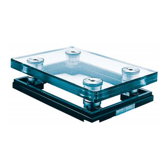
Multicomponent Force Plate with Glass Top Plate Type 9285B… General Description of the Instrument Introduction The multicomponent force plate Type 9285B… is a piezoelectric sensor assembly that allows the following measurands to be recorded: The 3 components F and F of a force F applied to the plate ... - Page 12 General Description of the Instrument Fig. 1: Multicomponent force plate for biomechanics Type 9285B… 9285B_002-499e-02.10 Page 9...
-
Page 13: Assembly Of The Force Plate
Multicomponent Force Plate with Glass Top Plate Type 9285B… Assembly of the Force Plate Assembly of the force plate. Fig. 2: Cross section through the force plate 1 3 component force measuring elements (force links) 2 Mounting base 3 Pressure pads 4 Hollow bolt 5 Top plate, replaceable 5 Cable channel... - Page 14 General Description of the Instrument Fig. 2 shows the force plate assembly. Each pair of 3- component force links Type 9067 or 9068 (1) are mounted between the Force plate frame (2) and the four pressure pads (3) with four hollow bolts (4)$$, each with a preload of 160 kN.
- Page 15 Multicomponent Force Plate with Glass Top Plate Type 9285B… Fig. 3: Assembly and dimensions Page 12 9285B_002-499e-02.10...
-
Page 16: Mounting, Installation And Putting Into Operation
In particular, it must be mounted exactly to specification to avoid being damaged by overloads (such as excessive internal stresses, etc.). For nonobservance of the mounting instructions Kistler will decline all responsibility. Installation Modes The force plate Type 9285B… may be set up in position in principle. - Page 17 Multicomponent Force Plate with Glass Top Plate Type 9285B… Important The force plate is not suitable for outdoor use. A gap of at least 2 mm must be left free between the force plate and the surrounding floor. Floor coverings such as Tartan or other types of surfacing must also be interrupted at the edge of the force plate to avoid a force bypass...
- Page 18 Mounting, Installation and Putting into Operation Fig. 4: Foundations with mounting frame for photographic applications (suggested arrangement) 9285B_002-499e-02.10 Page 15...
-
Page 19: Installing The Force Plate
Multicomponent Force Plate with Glass Top Plate Type 9285B… Installing the Force Plate Once the mortar has set, the plate (and any mirror) can be mounted. Mounting procedure (see Fig. 2 … 6) The assembly must be prepared for mounting by removing the glass top plate, the decoupling pieces and the flanges one after the other: ... - Page 20 Mounting, Installation and Putting into Operation Mounting force plate Lay the force plate frame on the mounting frame in its mounting position as shown in Fig. 5: Press down on alternate diagonally opposite corners of the force plate frame to check whether it is lying evenly on the mounting frame.
- Page 21 Multicomponent Force Plate with Glass Top Plate Type 9285B… Fig. 6: Mounting top plate on frame Fixing bolt Flange Cylinder head screw Top plate Fixing bolt Decoupling piece Page 18 9285B_002-499e-02.10...
- Page 22 Mounting, Installation and Putting into Operation Tapped holes for the eyebolts and the clearance around the heads of the necked bolts can be filled with Sylgard 170 (part of delivery) if desired Important Before tightening fixing screws make sure that there are no extreme temperature differences between force plate and mounting frame or foundation.
-
Page 23: Basic Circuitry And Cabling Of The Measuring System
The following rules should be observed when cabling the measuring station: Between force plate and charge amplifier the special cables supplied by Kistler must be used Ordinary cables may be used to link the charge amplifiers with the display or evaluation instruments ... -
Page 24: Connections With Built-In Amplifier (Type 9285B
Mounting, Installation and Putting into Operation Connections with Built-In Amplifier (Type 9285B...) The following figure shows the elements required for a complete measuring system. ® Fig. 7: Measuring system with BioWare and two force plates Type 9285BA Instead of the BioWare software system also other processing and indicating instruments can be connect to the force plate. -
Page 25: Connector Of Force Plate Type 9285B
Multicomponent Force Plate with Glass Top Plate Type 9285B… 4.6.1 Connector of Force Plate Type 9285B... with Built-In Amplifier Exct. GND Operate Control GND N.C. (reserved) x1+2 10 F x3+4 11 F y1+4 12 F y2+3 13 A' (Range z select) 14 Signal GN 15 N.C. -
Page 26: Cable Type 1758A
Mounting, Installation and Putting into Operation 4.6.2 Cable Type 1758A... A cable Type 1758A... (Fischer 19 female) connects the Fischer 19 female connector of the force plate to a D-Sub 37 pole female connector and is compatible with all BioWare data acquisition systems. Signal GND Signal GND Signal GND... -
Page 27: Digital Control
Multicomponent Force Plate with Glass Top Plate Type 9285B… 4.6.3 Digital Control All Digital Inputs are isolated with optocouplers: Fig. 11: Digital Control input circuit Logical Signal Dig. Input <4,4 V 5 ... 45 V Table 1: Digital Control input signals Range Select Group I F (Shear) Range Select Group II F... -
Page 28: Operation
Operation Operation Range Selection Below are range recommendations for different applications. It is important that for every application the smallest possible range is chosen. This will take full advantage of the maximum output voltage thus keeping noise and other errors the smallest possible. If, however, too small a range is chosen, one or more analog channels may be loaded beyond the limit of the possible measuring range (maximum output voltage). -
Page 29: Usable Frequency Range
Multicomponent Force Plate with Glass Top Plate Type 9285B… 5.2.1 Balance Analysis, Posturography It is imperative the charge amplifier is switched to OPERATE before the subject steps onto the force plate. Otherwise Center of Pressure COP can not be calculated correctly. Usable Frequency Range The force plate Type 9285B…... -
Page 30: Temperature Influences
Operation Temperature Influences The fact that the temperature coefficient of the sensitivity is negligibly small means the sensitivity of the sensors does not change with temperature. However, temperature gradients lead to generation of an error signal in the form of drift. This deviation with temperature depends on the heat input and is particularly evident while the temperature of the preloading elements is changing. -
Page 31: Maintenance
(zero offset and drift) is most likely to arise. Work on the charge amplifier requires special equipment and service personnel trained by Kistler. Zero shift and drift tests can be performed directly at the analog output pins with the voltmeter function of BioWare or a similar software package or with another voltmeter. -
Page 32: Weekly Function Check
Maintenance Weekly Function Check The system check should be performed weekly. 6.2.1 System Check Checking the system ensures that each channel of the force plate is outputting a signal that is correctly amplified in the charge amplifier and output to the data acquisition system. -
Page 33: Maintenance
Do not put a damaged instrument into operation Leave all repairs (e.g. replacement of damaged plug and socket connections or defective sensors) to Kistler trained service personnel Cleaning and Sterilization In principle, because of the usual high temperatures sterilization of the force plate is not permissible. -
Page 34: Troubleshooting
If a major repair is involved, you will receive a cost estimate Kistler will endeavor to repair your force plate as quickly as possible and at minimum cost, and to return it as good as new ... -
Page 35: Technical Data
Multicomponent Force Plate with Glass Top Plate Type 9285B… Technical Data Dimensions and Connections Fig. 12: Dimensions and connection of the multicomponent force plate Type 9285B... Page 32 9285B_002-499e-02.10... -
Page 36: Technical Data For Type 9285B
Technical Data Technical Data for Type 9285B... 8.2.1 General Measuring range –2,5 ... 2,5 0 ... 10 Overload –6/6 0/12 ±0,5 Linearity %FSO Hysteresis %FSO <0,5 ±2,0 Crosstalk <–> F ±2,0 –> F –> F ±0,5 4 Max. COP error 6... - Page 37 Multicomponent Force Plate with Glass Top Plate Type 9285B… Threshold <250 Drift mN/s <5 mN/s <10 Supply voltage 10 … 30 45 Supply current Output voltage 0 … ±5 Output current –2 … 2 Control inputs (optocoupler) 5 … 45 0,4 …...
-
Page 38: Built-In 8 Channel Charge Amplifier
Technical Data 8.2.2 Built-In 8 Channel Charge Amplifier 9285B_002-499e-02.10 Page 35... -
Page 39: Glossary
There are two different coordinate systems in use. In these operating instructions, the Kistler coordinate system is used exclusively. Kistler Coordinate System The following coordinate system is used for all Kistler force plates. Fig. 13: Kistler coordinate system Page 36... -
Page 40: Parameters Calculation
Glossary 9.2.1 ISB Coordinate System The ISB (International Society of Biomechanics) proposes the following coordinate system. Fig. 14: ISB coordinate system In the ISB-system not the active (acting) but counteracting (reacting) forces are described. The ISB coordinate system is used above all in connection with comprehensive movement analyses. -
Page 41: Warranty
Multicomponent Force Plate with Glass Top Plate Type 9285B… 10. Warranty Regarding the warranty reference is made to the agreement between the respective contracting parties. Page 38 9285B_002-499e-02.10... -
Page 42: Declaration Of Conformity
Declaration of Conformity 11. Declaration of Conformity EG-Konformitätserklärung EC Declaration of conformity / Déclaration de conformité CE Hersteller Kistler Instrumente AG Manufacturer / Fabricant CH-8408 Winterthur erklärt, dass das Produkt declares that the product / déclare que le produit Name /... - Page 43 Multicomponent Force Plate with Glass Top Plate Type 9285B… With External Amplifier Force Plate Cable Amplifier Data Acquisition Type 9281E Type 1686A... Type 9865E... Type 5691A1 with cable Type 1769A Type 9285 Type 1685B... Type 9286B Type 1685B... Type 2812A… Type 9287C Type 1686A...
Need help?
Do you have a question about the 9285B Series and is the answer not in the manual?
Questions and answers