
Related Manuals for Kistler 9366CD


Summary of Contents for Kistler 9366CD
- Page 1 Instruction Manual Multicomponent Force Link Set Type 9366CD 9366CD_002-412e-04.23...
- Page 3 Foreword Foreword Information in this document is subject to change without notice. Kistler reserves the right to change or improve its products and make changes in the content without obligation to notify any person or organization of such changes or improvements.
-
Page 4: Table Of Contents
Multicomponent Force Link Set, Type 9366CD Content Introduction..........................4 Important Information ....................... 5 For Your Safety ..........................5 How to Treat the Instrument ......................6 Tips for Using the Instruction Manual ....................6 What Happens After Modifications? ....................6 General Description of the Instrument ..................7 What Does a Multicomponent Force Plate Do? ................ - Page 5 Content Annex ............................38 Glossary ............................38 Measurement Uncertainty ......................41 Linearity ............................42 Frequency Range ..........................44 Influence of Temperature ....................... 45 Total pages: 46 9366CD_002-412e-04.23 Page 3...
-
Page 6: Introduction
It will help you with the installation, maintenance, and use of this product. To the extent permitted by law Kistler does not accept any liability if this instruction manual is not followed or products other than those listed under Accessories are used. -
Page 7: Important Information
Important Information 2. Important Information Please keep to the following rules without fail. This will ensure your personal safety when working, and assure long, trouble-free performance by the instrument. 2.1 For Your Safety This instrument has been tested thoroughly and it left the works in a perfectly safe condition. -
Page 8: How To Treat The Instrument
Please keep this Instruction Manual in a safe place where they can be consulted any time. If the instructions get lost, just turn to your Kistler distributor and they will be replaced without delay. 2.4 What Happens After Modifications? Modifications to instruments result in alterations of the Instruction Manual as a rule. -
Page 9: General Description Of The Instrument
General Description of the Instrument 3. General Description of the Instrument 3.1 What Does a Multicomponent Force Plate Do? The multicomponent force plate provides dynamic and quasi- static measurement of the 3 orthogonal components of a force (F ) acting from any direction onto the top plate. With the aid of optional evaluation devices the 3 moments M and M can be measured as well. -
Page 10: Functional Principle
Multicomponent Force Link Set, Type 9366CD 3.2 Functional Principle The force to be measured is introduced via a top plate and distributed among four triaxial force sensors arranged in a force measuring element. Each of the sensors has three pairs of quartz plates, one sensitive to pressure in the z direction and the other two to shear in the x and y directions respectively. -
Page 11: Design Of The Multicomponent Kit
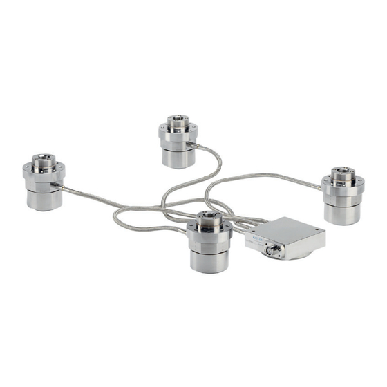
General Description of the Instrument 3.3 Design of the Multicomponent Kit The multi-component force link kit consists of four force measuring elements and a summing box with integrated cables. Each force link contains a preloaded triaxial force sensor. The 3-core cables of the summing box are routed in protective hoses and the screw connections to the sensor are marked with the corresponding position of the force measuring platform. -
Page 12: Assembly, Installation And Putting Into Operation
Multicomponent Force Link Set, Type 9366CD 4. Assembly, Installation and Putting Into Operation 4.1 Important Remarks The multicomponent force plate is a precision instrument, but its inherent accuracy can be exploited and retained only if it is treated with care. The following rules should therefore be... -
Page 13: Design Variants Of Force Plate
Assembly, Installation and Putting Into Operation 4.2 Design Variants of Force Plate Variant 2 Variant 1 Standard model Top plate Variant 3 Variant 4 Variant 2 Fig. 4: Design variants of force plates Variant 1: Main solution for minimum overall height Variants 2, 3 and 4: Additional solutions 9366CD_002-412e-04.23 Page 11... -
Page 14: Size Of Top Plate
Multicomponent Force Link Set, Type 9366CD 4.2.1 Size of Top Plate The cover plate must be between 300x300 mm (minimum) and 900x900 mm (maximum) in size. Steel versions chosen must not exceed 600x600 mm. A cable length of 0.5m is long enough for cover plates up to 750x750 mm in size. -
Page 15: Suggested Cover Plate Materials
Assembly, Installation and Putting Into Operation 4.2.2 Suggested Cover Plate Materials Steel DIN 1.4057* X17CrNi162 DIN 1.4021* X20Cr13 DIN 1.2316* X36CrMo7 DIN 1.1191 Ck45 rust-resistant Aluminum DIN 3.4345 Al Zn Mg Cu0.5 EN AW-7022-T651 4.2.3 Thickness of Top Plate The thickness depends on the size, load and material of the top plate. -
Page 16: Measuring Ranges
Multicomponent Force Link Set, Type 9366CD 4.2.5 Measuring Ranges The maximum allowed measuring range of the force plate depends on the dimensions and material of the top plate and on the point of force application. The maximum measuring ranges (see Fig. 7) applied for a point of force application within and no more than 100 mm above the surface of the top plate. -
Page 17: Natural Frequency
Assembly, Installation and Putting Into Operation 4.2.6 Natural Frequency A carefully mounted force plate of the recommended thickness achieves the following approximate natural frequencies. Fig. 8: Natural frequency as a function of cover plate length 9366CD_002-412e-04.23 Page 15... -
Page 18: Cover Plate Mounting Dimensions
Multicomponent Force Link Set, Type 9366CD 4.2.7 Cover Plate Mounting Dimensions The dimensions for mounting the force links on the cover plate for the four variants listed in Section 4.2 are given below. Variant 1 Top plate Fig. 9: Mounting dimensions of... - Page 19 Assembly, Installation and Putting Into Operation Variant 2 Top plate Intermediate ring Fig. 10: Mounting dimensions of variant 2 The force link can only be aligned using the alignment surfaces. 9366CD_002-412e-04.23 Page 17...
- Page 20 Multicomponent Force Link Set, Type 9366CD Variant 3 Top plate Intermediate ring Fig. 11: Mounting dimensions of variant 3 The force link can only be aligned using the alignment surfaces. Page 18 9366CD_002-412e-04.23...
- Page 21 Assembly, Installation and Putting Into Operation Variant 4 Top plate Intermediate ring Intermediate ring bottom Fig. 12: Mounting dimensions of variant 4 The force link can only be aligned using the alignment surfaces. 9366CD_002-412e-04.23 Page 19...
-
Page 22: Mounting Set On Cover Plate
Multicomponent Force Link Set, Type 9366CD 4.3 Mounting Set on Cover Plate The mounting diagram on the type label shows: Connector summing box Position of force measuring elements with respective series number Coordinate system Fig. 13: Type label of multicomponent force link set... - Page 23 Assembly, Installation and Putting Into Operation Attach the cables to the correspondingly numbered force links. Fix the summing box on the top plate. Insert the two ø4 mm positioning pins for force link 1 into the prepared holes. Clean the bearing surfaces on top plate and force measuring element.
- Page 24 Multicomponent Force Link Set, Type 9366CD Instead of using positioning pins, the force links can also be aligned using a straightedge. As shown in Figure 16, this is achieved by laying the straightedge against each pair of force links. straightedge reference surface Fig.
- Page 25 Assembly, Installation and Putting Into Operation Fix the force measuring elements to the top plate with two screws M6x20 each (tighten screws lightly). Attention screws good quality property class 12.9 (DIN 267). Mount force links 2, 3 and 4 as described under steps 4 to Turn over force plate and screw home all 32 fastening screws by hand to the stop.
-
Page 26: Installing The Force Plate
Multicomponent Force Link Set, Type 9366CD 4.4 Installing the Force Plate To install the force plate correctly please observe the following points: The force plate must be installed only by persons familiar with the device and sufficiently qualified for this work. -
Page 27: Basic Circuity And Cabling Of The Measuring System
Assembly, Installation and Putting Into Operation Important Before tightening the fastening screws consideration should be given that there are no extreme temperature differences between the force plate and mounting surface. Otherwise there is the danger of high internal stresses between force plate and mounting surface when the temperatures adjust. -
Page 28: Triaxial Force Measurement
Multicomponent Force Link Set, Type 9366CD [BM1] 4.6 Triaxial Force Measurement The form of construction of a force plate consisting of four triaxial force links with a common base and cover plate ensures the acting forces do not exert any moments on the individual force link. - Page 29 If there is a possibility of the acting loads damaging the dynamometer, please contact your Kistler Customer Service Center, where an analysis can be carried out for your load case.
-
Page 30: 6-Component Force Measurement
Multicomponent Force Link Set, Type 9366CD 4.7 6-Component Force Measurement For 6-component force measurement the output signals of the four triaxial force sensors are connected as shown in the diagram. Fig. 18: Connection of the twelve sensor outputs for 6-component force measurement... -
Page 31: Operation
Operation 5. Operation 5.1 Range selection Use of charge amplifiers with sensitivity adjustment (such as Type 5080A...) is recommended for the force plate. Adjust the sensitivities according to the data in the calibration sheets for the channels F and F . - Page 32 Multicomponent Force Link Set, Type 9366CD a Set the amplifier to <Reset>. Choose the range for F follows: 20 kN (amplifier to <Long Time Constant>). b Switch the amplifier to <Operate>. c Apply F (start machine tool). d After reading off and/or recording the force, switch the amplifier to <Reset>...
-
Page 33: Useful Frequency Range
Operation Useful Frequency Range In the resonant range a force link or a dynamometer exhibits mildly damped vibration characteristics. It is possible to measure up to about one third of the natural frequency without excessive errors. The lower frequency limit is determined by the drift of the charge amplifier and the quality of the insulation. - Page 34 Multicomponent Force Link Set, Type 9366CD Rule of thumb The better the force link (dynamometer) is mounted on the bench support and the better the part used to introduce the force is mounted on the link the higher the resonant frequency and hence the useful frequency of the measuring system.
-
Page 35: Temperature Influences
Operation 5.4 Temperature influences The temperature coefficient of the sensitivity (sensitivity change with temperature, the entire force plate being at the same temperature) is negligibly small. Temperature changes on the other hand give rise to an error signal in the form of a zero drift. This temperature drift is a function of the heat input. -
Page 36: Maintenance
Recalibration of the sensor is necessary, for example, after an uncontrolled overload. This recalibration must be carried out in the manufacturer's factory. Please contact your Kistler distributor in this case. Our products can be recalibrated or checked using the method used prior to initial dispatch. Our subsidiaries can also sometimes calibrate using the same or similar methods. -
Page 37: Troubleshooting
Troubleshooting 7. Troubleshooting 7.1 Diagnosis and Rectification of Faults Below is a list of typical faults, together with their causes and remedies. If you cannot deal with a fault, please consult your Kistler distributor. Fault Cause Remedy Signal line broken No measuring signal at charge Check measuring rig (connections). -
Page 38: Defective Multicomponent Kit
Proceed as follows if your force plate is defective Contact your Kistler distributor and advise him that you are sending in the defective instrument. Send the defective kit in its original packing to your Kistler distributor. Give an exact description of the trouble and the... -
Page 39: Technical Data
Technical Data 8. Technical Data For all technical data and references to accessories etc. please consult the data sheet of the Multicomponent Force Link Set 9366CDsp on www.kistler.com. 9366CD_002-412e-04.23 Page 37... -
Page 40: Annex
Kistler special cables and Kistler charge amplifiers are used. Calibrated measuring range Measuring range or part of the measuring range for which the sensor has been calibrated. Because of the high linearity of quartz crystal sensors, the sensitivity of a measuring range can usually also be used for smaller measuring ranges. - Page 41 Annex Disturbance Forces, moments and environmental influences acting on the sensor such as the temperature, which the sensor does not measure as a measurand and which produce an output signal (error). Example: when an additional bending moment acts on a force sensor. Drift Unwanted changes in the output signal independent of the measurand as a function of time.
- Page 42 See "Coulomb". piezoelectric The characteristic of quartz crystals in which mechanical loading produces a proportional electric charge. quasistatic Describes the ability of Kistler sensors and charge amplifiers to undertake short-term measurements or DC-similar measure- ments. Range see "Measuring range"...
-
Page 43: Measurement Uncertainty
Laboratory charge amplifier ±0,2 ... 0,5 % FSO Industrial charge amplifier ±1 % FSO Higher accuracy can be achieved with the following procedures: Calibration in the Kistler factory Calibration with charge amplifier Type 5395A Restriction of the temperature range ... -
Page 44: Linearity
Multicomponent Force Link Set, Type 9366CD This requirement is found mainly in repetitive measurements in production processes, where good repeatability is usually sufficient for process monitoring. Accuracy primarily plays only a subordinate role, when measurements can be directly related to confor-ming/nonconforming parts. - Page 45 Annex Best straight line – mathematical definition The minimization of maximum deviation is known as Chebyshev’s approximation. The best straight line is determined as follows: x = measurand (reference) Q = sensor charge signal or output signal from the charge ...
-
Page 46: Frequency Range
Multicomponent Force Link Set, Type 9366CD 9.4 Frequency Range Because of their mechanical quality, piezoelectric sensors have very low damping. The useful frequency range is limited in the upwards direction by the increasing resonance rise. Key: Measuring frequency Natural frequency... -
Page 47: Influence Of Temperature
Annex In their dynamic behavior, piezoelectric sensors are superior to all other measuring methods. Their high rigidity results in the highest possible natural frequencies. Piezoelectric sensors are thus ideal for measuring measurands which change rapidly over time. Their dynamic behavior is thereby largely determined by the surrounding structure. - Page 48 Multicomponent Force Link Set, Type 9366CD Temperature gradient error (dynamic error) A temporary change in the output signal is denoted as temperature gradient error, when the temperature of the environment or surrounding medium changes with a certain rate. In this case, the sensor is not in thermal equilibrium with the environment.
Need help?
Do you have a question about the 9366CD and is the answer not in the manual?
Questions and answers