
Related Manuals for Kistler 9813C Series


Summary of Contents for Kistler 9813C Series
- Page 1 Instruction Manual KiRoad Wireless for RoaDyn S6 Wheel force transducers On-board Unit Type 9813C... Wheel Unit Type 9822A... Rotary Encoder Type 5262A... 9813C_002-952e-10.23...
- Page 3 © 2021 ... 2022 Kistler Group. Kistler Group products are protected by various intellectual property rights. For more details visit www.kistler.com. The Kistler Group includes Kistler Holding AG and all its subsidiaries in Europe, Asia, the Americas and Australia.
-
Page 4: Table Of Contents
KiRoad Wireless HDR, Type 9813C... and Type 9822A... Contents Introduction ..........................4 Important notes ...........................5 For your safety ........................5 Disposal instructions for electrical and electronic equipment ..........6 Handling of Wheel Units .....................7 Software upgrades and updates ..................10 Product description ........................11 Overview ...........................11 System overview ......................12 Accessories ........................13 Further documents ......................14... - Page 5 Troubleshooting ........................50 Cables and power supply ....................50 On-board Unit status display and LED ................50 Interpretation of the status bits ..................50 Software ...........................52 CAN ..........................52 Environmental conditions ....................53 EMC interference ......................53 Service ..........................53 Other information ........................54 EU declaration of conformity ....................55 Total pages 55 9813C_002-952e-10.23 Page 3...
-
Page 6: Introduction
It will help you with the installation, maintenance, and use of this product. To the extent permitted by law Kistler does not accept any liability if this instruction manual is not followed or prod- ucts other than those listed under Accessories are used. -
Page 7: Important Notes
Important notes For your safety Observe the following remarks before you commission the device. Kistler accepts no responsibility for damages that could arise from improper use of this product. Prerequisite for the proper and safe use of the device is... -
Page 8: Disposal Instructions For Electrical And Electronic Equipment
Kistler assumes no liability for damages caused due to the use of cables other than those delivered by Kistler. For additional information, please contact Kistler: +49 7031 3090 0 info.de@kistler.com... -
Page 9: Handling Of Wheel Units
Important notes Handling of Wheel Units The Wheel Units are equipped with a built-in, high- performance battery with a capacity of 6.5 Ah. 2.3.1 Further documents UL (Underwriters Laboratories Inc.): ƒ Standard for Lithium Batteries ƒ UL 1642 - Fifth Edition, March 2012 UN (United Nations): ƒ... - Page 10 KiRoad Wireless HDR, Type 9813C... and Type 9822A... Storage outside of these temperatures can lead to a greater amount of self discharge, lower performance and swelling of the battery cells. Minimum charge level during storage A minimum charge level of 3.62 V at the end of storage is necessary to prevent deep discharge.
- Page 11 Important notes 2.3.3 Using the Wheel Units after a long storage period After a long storage period, the following procedure is rec- ommended: ƒ Complete discharging of the battery ƒ Preferably, run a complete charge / discharge cycle. Otherwise, it may take 2 to 3 cycles until the maximum capacitance is available again ƒ...
-
Page 12: Software Upgrades And Updates
Kistler may occasionally supply upgrades or updates for embedded software. Such upgrades or updates must always be installed. Kistler declines all liability for any direct or consequential damages caused by products running on embedded soft- ware that has not been upgraded or updated to the latest available version. -
Page 13: Product Description
4 RoaDyn trans- ducers. If a Kistler DTI-Logger is used for data acquisition, only one cable is required for the On-board Unit to transfer the data, to provide power, and configure the On-board Unit via KiCenter. -
Page 14: System Overview
KiRoad Wireless HDR, Type 9813C... and Type 9822A... On-board Unit Wheel Unit RoaDyn WFT Rotary Encoder Fig. 1: KiRoad Wireless HDR system components System overview Fig. 2: KiRoad Wireless HDR system Page 12 9813C_002-952e-10.23... -
Page 15: Accessories
Product description Accessories 3.3.1 Included accessories Wheel Unit Ordering No. Component 18043616 Wheel Unit S6 (without exchangeable accumulator battery) 3.3.2 Optional accessories Wheel Unit Ordering No. Component 18044044 Exchangeable accumulator battery incl. charging tray, charging device and mains cable EU 18044086 Exchangeable accumulator battery 18044087... -
Page 16: Further Documents
KiRoad Wireless HDR, Type 9813C... and Type 9822A... 3.3.5 Included accessories Rotary encoder Component Ordering No. Central contacting (customer-specific) Type 9711A4 for CFRP wheel force transducers Customized Type 9711A5 for ALU wheel force transducers Rotary encoder Angle encoder Customized Angle disk / insulating disk with spacer sleeves Pincer clamp Wheel mounting bolts Customized... -
Page 17: Technical Data
Technical data Technical data Specifications Wheel Unit, Type 9822A... System specifications Dimensions (LxWxH), approx. 184x184x62,8 Weight Temperature range Operation °C –20 ... 50 Storage °C –40 ... 50 Power supply lithium-Ion accumulator battery Number of load cycles >500 Wireless standard IEE 802.11n Transmitted channels Forces... -
Page 18: Specifications On-Board Unit, Type 9813C
KiRoad Wireless HDR, Type 9813C... and Type 9822A... Specifications On-board Unit, Type 9813C... System specifications Dimensions (LxWxH), approx. 181x125x149 Weight grams 2,500 Operating temperature range °C –20 ... 50 Degree of protection (cable mounted) IP40 Power supply 10 ... 28 Power consumption max. -
Page 19: Installation And Connections
Installation and connections Installation and connections Description of the Wheel Unit and overview of the LED codes Fig. 3: KiRoad Wireless HDR Wheel Unit Initialization switch Indicator LEDs Each LED on the control panel represents a wheel posi- tion number (position 3 is used as an example in the fol- lowing descriptions). - Page 20 KiRoad Wireless HDR, Type 9813C... and Type 9822A... <2 s Initialization: Indicates the position that is requested (the corresponding LED lights up for 3 seconds) Measurement: Displays the assigned position (the corresponding LED lights up for 3 sec- onds) and performs a wheel search (hot-plugin). It is not necessary to supply power to the Wheel Unit again to detect a connected wheel if it has been mounted (or removed) after pow- er-on.
- Page 21 Installation and connections Positioning procedure Start sequence for positioning [1+2►2+3►3+4►off]: The activation of the positioning mode is indicated by this short LED sequence. After that, the system switches to return mode and the user must press the power button within 5 seconds to change the selection (see next steps).
- Page 22 Irregular condition of the Wheel Unit. Switch the Wheel Unit on again. If this error occurs frequently, a firmware update may help. If a firmware update is not successful, contact your Kistler Service or send the device for inspection. Page 20...
-
Page 23: Description Of The On-Board Unit
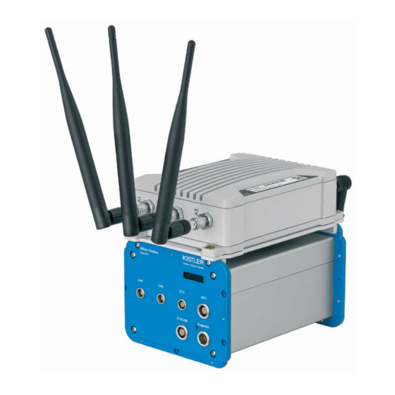
Installation and connections Description of the On-board Unit Fig. 5: KiRoad Wireless HDR On-board Unit Power / DTI Ethernet / USB (no function) Analog output Display Antenna connections Initialization switch Undervoltage (<10 V) can cause the On-board Unit to restart and thus interrupt the transmission of data. If several On-board Units are used, only one can be connected to the measurement computer via USB! Otherwise, there are undefined system states due to IP... -
Page 24: Commissioning
KiRoad Wireless HDR, Type 9813C... and Type 9822A... Commissioning Charging the Wheel Unit The Wheel Unit with exchangeable accumulator battery can be unlocked and then removed via a locking system. Only use the original accessories to charge the exchangeable accumulator battery! Mount the country-specific power plug onto the charging device. - Page 25 Commissioning ƒ Place the exchangeable accumulator battery in the charging tray. Fig. 7: Charging the Wheel Unit, charging tray with exchangeable accumulator battery ƒ Place the exchangeable accumulator battery in the charging tray. ƒ Plug the charging connectors of the charging device into the charging tray sockets.
- Page 26 KiRoad Wireless HDR, Type 9813C... and Type 9822A... The 18044087 charging tray has a charge level indicator (1), connection sockets for the prescribed charger (2), a green LED (3), which signals that the charging tray is supplied with power and a red LED (4), which lights up in the event of shutdown due to overtemperature.
-
Page 27: Installing And Adjusting The Rotary Encoder On The Vehicle
Commissioning Installing and adjusting the rotary encoder on the vehicle 6.2.1 Setup with aluminum inner part Optional Fig. 8: Setup with the aluminum inner part Central contactor Aluminum inner part (existing inner parts can be reworked) Rotary encoder Optional: retrofit package (centering sleeve and insulating disk) 9813C_002-952e-10.23 Page 25... - Page 28 KiRoad Wireless HDR, Type 9813C... and Type 9822A... 6.2.2 Setting up the rotary encoder Tightening torque: 2.1 Nm Tightening torque: 2.1 Nm Tightening torque: 0.9 Nm Tightening torque: 2.1 Nm Fig. 9: Setting up the rotary encoder Insulating disk with pitch circle diameter of the wheel force transducer Aluminum inner part (existing inner parts can be reworked)
- Page 29 Commissioning Insert the central contactor and screw it on from the other side. Fig. 11: Installing the central contactor, step 2 The central contactor is fixed onto the ring of the inner part with 10 x hexagon socket screws, M1, 6x6 (55062156). 6.2.4 Optional: installing the centering sleeve with the insulating disk (retrofit) Fig.
- Page 30 KiRoad Wireless HDR, Type 9813C... and Type 9822A... 6.2.5 Adjusting and aligning the rotary encoder Mount the vehicle-specific ET adapter with the wheel bolts on the vehicle's hub. Use the spacers and the pincer clamp to adjust the exact position of the rotary encoder. Hexagon socket screw, I-6k M4x10 55075431 Hexagon socket screw, I-6k...
- Page 31 Commissioning Plug the rotary encoder onto the ET adapter, then center the rotary encoder over the special wheel mounting bolts. Hexagon socket screw, I-6k M4x6 55075430 Fig. 14: Adjusting the rotary encoder, step 2 The rotary encoder's gold contacts must be handled care- fully.
-
Page 32: Installation Of The On-Board Unit
KiRoad Wireless HDR, Type 9813C... and Type 9822A... Installation of the On-board Unit The On-board Unit is positioned and secured in the inte- rior of the vehicle. Never mount the KiRoad Wireless HDR On-board Unit or other equipment parts so that they come into contact with the airbag if it is triggered. -
Page 33: Connecting To The Network
Commissioning 6.3.2 Installation of the On-board Unit when using a DTI Logger Connect the DTI port to the DTI logger. Connect the DTI logger to a PC via Ethernet to configure the system and to be able to record measurement data. For configuring the system, see Chapter 6.5. -
Page 34: System Setup Using Kicenter
The soft- ware also offers the option to record the measurement data. Always use the current version of KiCenter. Check the Kistler website www.kistler.com periodically for any updates. 6.5.1 KiCenter: system requirements ƒ Operating system: Windows 10 ƒ... - Page 35 Commissioning 6.5.2 KiCenter: sensor and system settings After KiCenter starts, the KiRoad Wireless On-board Unit will have a green status in the "Device Tree" with its serial number. If this is not the case, click the "Browse All" but- ton again to search for connected devices. If it still does not connect after doing this, check the connections for the USB or LAN cables as well as the IP address for the KiRoad Wireless On-board Unit and the network settings...
- Page 36 KiRoad Wireless HDR, Type 9813C... and Type 9822A... Fig. 17: KiCenter screen view of the Status Page – without connected Wheel Units A node and 6 pages are displayed in the "Device Tree": ƒ Measurement Display ƒ Sensor Configuration ƒ Sensor Calibration ƒ...
- Page 37 ƒ Total Operating Hours in the Service Interval: Displays the cumulative operating hours for the On-board Unit since the last service interval with Kistler The wheel force transducer tiles display the most import- ant, current measured values for the individual wheel force transducers as well as additional information: ƒ...
- Page 38 KiRoad Wireless HDR, Type 9813C... and Type 9822A... 6.5.3 KiCenter: measurement display Fig. 18: KiCenter screen view -- Measurement Display The measurement display is used most of all to monitor the correct functioning of the system. Thus the system status and the current measuring range are displayed. In addition, the measurement data for the individual wheel torque transducers is displayed in order to check the plau- sibility of the measurement data.
- Page 39 Commissioning 6.5.4 KiCenter: sensor configuration Fig. 19: KiCenter screen view -- Sensor Configuration This sub-menu is used to configure the wheel positions and the network settings Wheel Positions The individual wheels can be adjusted corresponding to their installation position on the vehicle "left" or "right" Signal delay Display of the current signal delay, consisting of processor computing time and delay caused by the filter.
- Page 40 KiRoad Wireless HDR, Type 9813C... and Type 9822A... Wireless Settings The operating frequencies are adjustable between three channels: Channel 1: 2 412 MHz Channel 6: 2 437 MHz Channel 11: 2 462 MHz The default setting is always the "Automatic" mode. Network Settings DHCP Preset: Enabled.
- Page 41 Commissioning 6.5.5 KiCenter: Sensor calibration Fig. 20: KiCenter screen view -- Sensor Calibration The calibration matrix for the individual wheel force trans- ducers can be uploaded in the "Sensor Calibration" sub- menu. Press the "Load Calibration File" button and open the specific *.cm calibration file.
- Page 42 KiRoad Wireless HDR, Type 9813C... and Type 9822A... 6.5.6 KiCenter: analog output The output for the analog channels can be configured on the "Analog Output" page. The desired resolution and off- set can be set here. The analog outputs are only fully functioning when the On-board Unit was purchased with the "Calibrated Analog Outputs"...
- Page 43 Commissioning 6.5.7 KiCenter: CAN bus The settings for the CAN bus can be adjusted on the "CAN Bus" page. Fig. 22: KiCenter screen view -- CAN Bus Baud Rate Preset: 1 MBaud Transmission speed of the CAN bus protocol. Must match the settings in the data acquisition system.
- Page 44 KiRoad Wireless HDR, Type 9813C... and Type 9822A... Send Mode ƒ Continuous Transmission: The data is transmitted continuously with the set interval time. The system operates internally with an interval time of 2 ms. If the transmission interval is increased, every measured value is no longer output via the CAN bus.
- Page 45 Commissioning Creating a CAN DB It is possible to generate CAN database files (CAN DB) using the KiCenter software. CAN DB can only be created on the Status page. In order to begin generating a CAN DB, click the top right button "Create CAN DB File".
-
Page 46: Firmware Update
KiRoad Wireless HDR, Type 9813C... and Type 9822A... 6.5.8 KiCenter: CAN DBC names This menu item enables individual names to be assigned to the individual channels. Fig. 24: KiCenter screen view – CAN DBC Settings Firmware update Because the sensors are constantly undergoing devel- opment, it may be necessary to update the firmware for them. -
Page 47: Operation
Operation Operation Configuration of the wheel force transducers (settings) The first time your RoaDyn WFT is connected to KiRoad Wireless HDR you need to set up the sensor parameter and calibration matrix by switching to Sensor Settings in the GUI menu. Here, you can configure Wheel Name, Wheel Position, Angle Steps and Lever Arm and check the Loadcell Radius of the WFT. - Page 48 KiRoad Wireless HDR, Type 9813C... and Type 9822A... Signs for transforming from wheel to vehicle forces Left wheel (LF, LR) Right wheel (RF, RR) Fig. 25: Definition of the wheel/vehicle related coor- dinate systems using RoaDyn wheel force transducers and KiRoad Wireless HDR The angle steps are stored in the wheel angle encoder and are read out at system startup.
- Page 49 Operation Any changes in settings using the web-based GUI are not made until the "Save to Device" button is pushed and the current software configuration is transferred to the hard- ware unit. In the Calibration menu, the 6x6 hexapod calibration matrix for maximum sensor accuracy and crosstalk com- pensation can be assigned to the connected RoaDyn WFT.
-
Page 50: Preparing A Measuring Drive
KiRoad Wireless HDR, Type 9813C... and Type 9822A... Preparing a measuring drive Before any measurement is started, the WFT system must have been switched on for at least half an hour and the WFT must have cycled through at least two full revo- lutions to synchronize the angular measurement and to correct angle counting. - Page 51 Operation Live data from the connected RoaDyn WFT can be monitored on the Measurement Display. The refresh rate is limited by the web-browser display capability and sufficient for quasi-static measuring data check. This is strongly recommended for all Main Channels of each connected WFT before starting the real measurement and data capturing.
-
Page 52: Troubleshooting
KiRoad Wireless HDR, Type 9813C... and Type 9822A... Troubleshooting Cables and power supply ƒ Check that all connections are properly connected and that the system is connected to an appropriately designed power supply. ƒ Check that the correct cables have been used for all connections. - Page 53 Troubleshooting Transform the status bits (decimal) into a binary number. Below you can see an example for the status bit message 4.111: Read the binary code from the calculator. Then read the values from the table above. This means, that: ƒ...
-
Page 54: Software
KiRoad Wireless HDR, Type 9813C... and Type 9822A... Software ƒ If one or more output signals are incorrect, the sensor may have been set-up incorrectly via the KiCenter software. Check all of the settings in KiCenter: - All analog voltage settings must be within range and conform with the settings for the data acquisition system to which they are connected. -
Page 55: Environmental Conditions
+49 7031 3090 0 or by e-mail: info.de@ kistler.com. Please provide the following information: ƒ A ".kdx" file saved from the KiCenter software as an example of the problem or fault condition. -
Page 56: Other Information
KiRoad Wireless HDR, Type 9813C... and Type 9822A... Other information This information has been compiled from sources consid- ered to be authoritative and is accurate and credible as of the creation date to the best of our knowledge. How- ever, there is no claim to completeness or absolute credi- bility. -
Page 57: 10. Eu Declaration Of Conformity
EU Declaration of Conformity EU-Konformitätserklärung Déclaration UE de conformité The manufacturer / Der Hersteller / Le Fabricant: Kistler Instrumente GmbH, Umberto-Nobile-Straße 14, D-71063 Sindelfingen, Germany hereby declares that the product / erklärt hiermit, dass das Produkt / déclare que le présente produit:...
Need help?
Do you have a question about the 9813C Series and is the answer not in the manual?
Questions and answers