Table of Contents
Advertisement
Quick Links
Advertisement
Table of Contents

Related Manuals for Kistler 9255C


Summary of Contents for Kistler 9255C
- Page 1 Instruction Manual Quartz 3-Component Dynamometer Type 9255C 9255C_002-615e-02.15...
- Page 2 Instruction Manual Quartz 3-Component Dynamometer Type 9255C 9255C_002-615e-02.15...
- Page 4 Information in this document is subject to change without notice. Kistler reserves the right to change or improve its products and make changes in the content without obliga- tion to notify any person or organization of such changes or improvements.
-
Page 5: Table Of Contents
Recalibrating the Instrument ....................23 Maintenance Tasks ......................24 Trouble Shooting ......................... 25 Tracing Faults and Remedying Them .................. 25 Defective Dynamometer ....................26 Technical Data ..........................27 3-Component Dynamometer Type 9255C ................. 27 Accessories ......................... 29 Page 2 9255C_002-615e-02.15... - Page 6 Content Annex ............................30 Glossary ..........................30 Measurement Uncertainty ....................34 Linearity ..........................35 Frequency Range ........................ 37 Influence of Temperature ....................38 Total Pages 39 9255C_002-615e-02.15 Page 3...
-
Page 7: Introduction
It will help you with the installation, maintenance, and use of this product. To the extent permitted by law Kistler does not accept any liability if this instruction manual is not followed or prod- ucts other than those listed under Accessories are used. -
Page 8: Important Information
Important Information 2. Important Information 2.1 For Your Safety This instrument has been tested thoroughly and it left the works in a perfectly safe condition. To maintain this condition and assure safe operation, the user must observe the directives and warnings contained in these instructions ... -
Page 9: How To Treat The Instrument
Quartz 3-Component Dynamometer Type 9255C 2.2 How to Treat the Instrument The dynamometer may be used only under the specified environmental and operating conditions The insulation resistance is crucially important with pi- Ω ezoelectric measurements. It must be around 10 Ω) -
Page 10: Tips For Using The Instruction Manual
Please keep this Instruction Manual in a safe place where they can be consulted any time. If the instructions get lost, just turn to your Kistler customer service station and they will be replaced without delay. All information and directives in these instructions may be modified at any time without prior notification. -
Page 11: General Description Of The Instrument
Quartz 3-Component Dynamometer Type 9255C 3. General Description of the Instrument 3.1 What Does a Multicomponent Dynamometer Do? The multicomponent dynamometer provides dynamic and quasi-static measurement of the 3 orthogonal components of a force (F ) acting from any direction onto the top plate. -
Page 12: Functional Principle
General Description of the Instrument 3.2 Functional Principle The force to be measured is introduced via a top plate and distributed between four piezoelectric 3-component force sensors arranged between the base and top plates. Each of the sensors has three pairs of quartz plates, one sensitive to pressure in the z direction and the other two to shear in the x and y directions respectively. -
Page 13: Design Of The Dynamometer
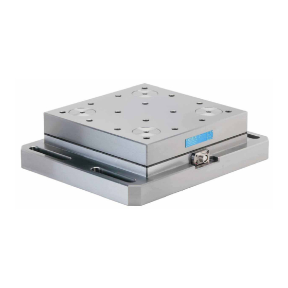
Quartz 3-Component Dynamometer Type 9255C 3.3 Design of the Dynamometer The dynamometer consists of four 3-component force sensors sandwiched under high preload between a baseplate and a top plate. This preload is needed to transmit the friction forces. Fig. 3: Design of the dynamometer... -
Page 14: Assembly, Installation And Putting Into Operation
Assembly, Installation and Putting into Operation 4. Assembly, Installation and Putting into Operation 4.1 Important Remarks The multicomponent dynamometer Type 9255C is a preci- sion instrument, but its inherent accuracy can be exploited and retained only if it is treated with care. The following rules should therefore be noted: ... -
Page 15: Positioning Of The Dynamometer
Quartz 3-Component Dynamometer Type 9255C To align the Dynamometer on the machine table one of the side wall of the flange can be used Make sure that the dynamometer rests absolutely flat. Even the smallest air gap will cause undesirable elasticity and reduce the resonant frequency of the measuring rig. -
Page 16: Basic Circuitry And Cabling Of The Measuring System
Assembly, Installation and Putting into Operation 4.4 Basic Circuitry and Cabling of the Measuring System The electrical charges (in pC) delivered from the measuring platform are converted by charge amplifiers into propor- tional voltages, which may be displayed, recorded or further processed with usual instruments. -
Page 17: Force Measuring With 3 Components (F )
Quartz 3-Component Dynamometer Type 9255C 4.4.1 Force Measuring with 3 Components (F The illustration below shows the elements needed to connect the dynamometer with a multichannel charge amplifier (e.g. Type 5070Ax01xxx). It is a ground-insulated measur- ing chain with 3-wire cable. -
Page 18: 3-Component Force Measurement
If there is a possibility of the acting loads damaging the dynamometer, please contact your Kistler Customer Service Center, where an analysis can be carried out for your load case. -
Page 19: Force And Moment Measuring With 6 Components (F )
Quartz 3-Component Dynamometer Type 9255C 4.4.3 Force and Moment Measuring with 6 Components (F The illustration below shows the elements needed to con- nect the dynamometer with an multichannel charge ampli- fier or with several single amplifiers (such as Type 5070Ax1xx). - Page 20 Depending on the analysis of the measuring results, the distance between the cover plate surface and the sensor center is the deciding factor. This distance is called az0. The value for Type 9255C is: az0 = 48.5 mm 9255C_002-615e-02.15 Page 17...
-
Page 21: Operation
Quartz 3-Component Dynamometer Type 9255C 5. Operation 5.1 Range Selection Use of charge amplifiers with sensitivity adjustment (such as Type 5070A) is recommended for the multicomponent dynamometer Type 9255C. Adjust the sensitivities according to the data in the calibration sheets for the channels F and F . - Page 22 Operation a Set the amplifier to <Reset>. Select the range for F as follows: 2 · 10 N/V (amplifier to <Long Time Constant>) b Switch the amplifier to <Operate> c Apply F (put the machine tool into operation) d After reading and/or recording the force, switch the amplifier back to <Reset>...
-
Page 23: Usable Frequency Range
Quartz 3-Component Dynamometer Type 9255C Usable Frequency Range At the upper frequency limit the frequency behaviour of the dynamometer shows oscillation with relatively little damping. Frequencies up to about one-third of the natural frequency can be resolved without excessive measuring er- rors. - Page 24 Operation Rule The better the mounting of the measuring device (force link, dynamometer) on a base structure and the firmer the attachment of the force introduction parts – the higher is the resonant frequency and the wider is the usable fre- quency range.
-
Page 25: Temperature Influences
Quartz 3-Component Dynamometer Type 9255C 5.4 Temperature Influences The temperature coefficient of the sensitivity (sensitivity change with temperature, the entire dynamometer being at the same temperature) is negligibly small. Temperature changes on the other hand give rise to an error signal in the form of a zero drift. This temperature drift is a function of the heat input. -
Page 26: Maintenance
The dynamometer must be recalibrated for example after an uncontrolled overloading. This recalibration should be carried out in the manufactur- er's factory. In such cases, please contact your Kistler dis- tributor. Our products can be recalibrated or tested the same way as when they were first delivered. -
Page 27: Maintenance Tasks
Clean the free nine-pin plug and socket connection of the dynamometer or connecting cable regularly with an extremely pure cleansing agent, such as Kistler cleansing and insulating spray Type 1003 or rectified benzene 9255C_002-615e-02.15... -
Page 28: Trouble Shooting
7. Trouble Shooting 7.1 Tracing Faults and Remedying Them Below is a list of typical faults, together with their causes and remedies. If you cannot deal with a fault, please consult your Kistler distributor. Fault Cause Remedy No measuring signal at Signal line broken Check measuring rig (connections). -
Page 29: Defective Dynamometer
Quartz 3-Component Dynamometer Type 9255C 7.2 Defective Dynamometer Proceed as follows if your dynamometer is defective: Contact your Kistler distributor and advise him that you are sending in the defective instrument Send the defective dynamometer in its original packing to your Kistler distributor ... -
Page 30: Technical Data
Technical Data 8. Technical Data Please note that all technical data and all other information in this section may be altered at any time without prior notice. 8.1 3-Component Dynamometer Type 9255C Range –30 ... 30 Force application within and max. - Page 31 Quartz 3-Component Dynamometer Type 9255C Fig. 8: Dimensions of dynamometer Type 9255C 9255C_002-615e-02.15 Page 28...
-
Page 32: Accessories
Technical Data 8.2 Accessories The accessories included in the scope of supply are shown in the current price list. For the dynamometer Type 9255C the following accessories are obtainable: Type Connecting cable (3- wire) (straight plug) 1687B5 (angle plug) 1689B5... -
Page 33: Annex
Cable capacitance The cable capacitance, and thus the length of the con- necting cable, has no noteworthy influence on the meas- uring result when Kistler special cables and Kistler charge amplifiers are used. Calibrated range Measuring range or part of the measuring range for which the sensor has been calibrated. - Page 34 Annex Disturbance Quantity that is not the measurand but that affects the result of the measurement. The contributions are expressed in terms of the measurand related to the acting quantity. Examples: • additional bending moment acts on a force sensor: →...
- Page 35 Describes the ability of Kistler sensors and charge amplifiers to undertake short-term measurements or DC-similar measurements. Range see "Measuring range"...
- Page 36 Annex Note: sensitivity of piezoresistive and strain gauge sensors is additionally dependent on the excitation current or volt- age. Sensor System which produces a definite change in the output signal as a function of the change of the measurand acting on it.
-
Page 37: Measurement Uncertainty
Quartz 3-Component Dynamometer Type 9255C 9.2 Measurement Uncertainty Systematic errors, accuracy Accuracy is the extent of the conformity between a meas- ured value and a true value of the measurand. In a piezoe- lectric measuring chain it is determined by many systematic errors, such as ... -
Page 38: Linearity
Errors due to zero drift caused by influences changing with time, such as the tem- perature, are thus basically excluded. With Kistler piezoelectric measuring chains, a typical repeata- bility within 0,1 % FSO can be assumed. 9.3 Linearity... - Page 39 Quartz 3-Component Dynamometer Type 9255C Best straight line – mathematical definition The minimization of maximum deviation is known as Che- byshev’s approximation. The best straight line is deter- mined as follows: x = measurand (reference) Q = sensor charge signal or output signal from the charge amplifier ...
-
Page 40: Frequency Range
Annex 9.4 Frequency Range Because of their mechanical quality, piezoelectric sensors have very low damping. The useful frequency range is lim- ited in the upwards direction by the increasing resonance rise. Key: f Measuring frequency Natural frequency Amplitude ratio The following approximate values apply to the amplitude error or achievable accuracy as a function of frequency: Accuracy 10 % ... -
Page 41: Influence Of Temperature
Quartz 3-Component Dynamometer Type 9255C In their dynamic behavior, piezoelectric sensors are superior to all other measuring methods. Their high rigidity results in the highest possible natural frequencies. Piezoelectric sensors are thus ideal for measuring measurands which change rapidly over time. Their dynamic behavior is there- by largely determined by the surrounding structure. - Page 42 Annex Temperature gradient error (dynamic error) A temporary change in the output signal is denoted as temperature gradient error, when the temperature of the environment or surrounding medium changes with a cer- tain rate. In this case, the sensor is not in thermal equilibri- um with the environment.
Need help?
Do you have a question about the 9255C and is the answer not in the manual?
Questions and answers