
Subscribe to Our Youtube Channel
Related Manuals for Kistler 9317C


Summary of Contents for Kistler 9317C
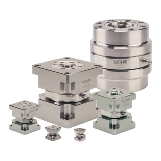
- Page 1 Instruction Manual Triaxial load cell Type 9317C Type 9327C Type 9347C Type 9367C Type 9377C Type 9397C 93x7C_002-893e-06.21...
- Page 2 Information in this document is subject to change without notice. Kistler reserves the right to change or improve its products and make changes in the content without obligation to notify any person or organization of such changes or improvements.
-
Page 3: Table Of Contents
Content Content Introduction ............................ 4 Important notes ..........................5 For your safety ........................5 Unpacking ..........................6 Notes on handling the instrument ..................6 Tips on the use of this instruction manual ................7 What happens in the event of changes? ................7 General description of the instrument .................... -
Page 4: Introduction
It will help you with the installation, maintenance, and use of this product. To the extent permitted by law Kistler does not accept any liability if this instruction manual is not followed or products other than those listed under Accessories are used. -
Page 5: Important Notes
Important notes 2. Important notes It is essential for you to study the following information, compliance with which is for your personal safety during the work and will ensure long, fault-free operation of the instrument. For your safety This instrument has been thoroughly tested and has left the factory in a perfectly safe condition. -
Page 6: Unpacking
Triaxial load cell Type 93x7C Unpacking Check all packaging for transport damage. Report any such damage to the transporters and to the authorized Kistler distributor. Notes on handling the instrument The load cell must only be used under the specified environmental and operating conditions. -
Page 7: Tips On The Use Of This Instruction Manual
Please keep these instructions in a safe place where they are always to hand. If you lose these instructions, please contact your Kistler customer service organization and you will receive a re- placement by return. All details and directions in these instructions are subject to change at any time without prior notice. -
Page 8: General Description Of The Instrument
Triaxial load cell Type 93x7C 3. General description of the instrument What is the purpose of a triaxial load cell? The piezoelectric triaxial load cell is used for the dynamic and quasistatic measurement of the three orthogonal components of any force acting on the sensor (F Triaxial force transducers measure: ... - Page 9 General description of the instrument Inertia force measurement Impact force measurement Fig. 2: Force Limited Vibration Testing on Fig. 5: Drop test installation for landing gears satellites Reaction force measurement Product testing Fig. 6: Rocket motor static test range Fig. 3: Athletics sprint start optimization Wheel force measurement Fig.
-
Page 10: Functional Principle
Triaxial load cell Type 93x7C Functional principle The force sensor contains three pairs of quartz plates, of which one is sensitive to pressure in the z direction and the two others to shear forces in the x and y directions. The type of sensitivity depends on the position of the cut from the quartz blank. - Page 11 General description of the instrument Fig. 9: Shear quartz and its reaction to a cross force The force to be measured is introduced via a top plate and distributed on the triaxial ring force transducer arranged between top and base plates. The force introduced is resolved into three orthogonal components.
-
Page 12: Assembly, Installation And Initial Start-Up
Triaxial load cell Type 93x7C 4. Assembly, installation and initial start-up Important notes The triaxial force transducer is a precision instrument which must be carefully handled if its inherent accuracy is to be maintained in a useful state. To measure the three components of a force vector the load cell must be mounted on a foundation plate (table). - Page 13 Recommended tightening torques for mounting screws Strength Tightening Triaxial class torque load cell Variant Thread acc. to MA [N·m] Type ISO 898/1 10.9 9317C Var. 1 12.9 10.9 Var. 2 12.9 9327C 10.9 Var. 1 12.9 10.9 Var. 2 12.9 9347C 10.9...
-
Page 14: Measuring Range/Introduction Of Force
Triaxial load cell Type 93x7C 5. Measuring range/introduction of force Triaxial Force Measurement using a Single 3 Axis Load Cell The maximum measuring range of an individual preloaded triaxial force sensor can only be utilized when the line of action of the resulting force vector runs through the center of the sensor, i.e. - Page 15 Measuring range/introduction of force When the force application point and the three components of the resulting force are known, the active moments can be calculated as follows: · a – F · a · a – F · a · a –...
- Page 16 Triaxial load cell Type 93x7C Fig. 13: generic Nomogram for graphical specifications Fig. 14: Maximum values to be filled in the nomogram Page 16 93x7C_002-893e-06.21...
- Page 17 Measuring range/introduction of force Example: Process data: Forces -1000 N 10000 N 8’000 N Application 0.005 m Coordinates 0.008 m Calculations: Load cell Type 9347C 70 kN Preload force Moments M · a – F · a = 64 N·m ·...
- Page 18 Triaxial load cell Type 93x7C Mathematical method: (1) The sum of the applied shear force F [%], the torsional moment M [%] and half the Bending moment M has to be equal or lower than the force in z-direction [%] + F [%]) (2) The bending moment M shall not exceed the allowed...
- Page 19 Measuring range/introduction of force 2) The applied bending moment M [30%] is within the boundaries, but reduces the limit for F and M �������� [ % ] ≤ �������� [ % ] → �������� �������� % ≤ �������� �������� % ��������...
-
Page 20: Triaxial Force Measurement Using A Dynamometer
Triaxial load cell Type 93x7C Triaxial force measurement using a Dynamometer The configuration of a dynamometer consisting of four triaxial ring force transducer with common base plate and cover plate ensures the acting forces do not apply any moments to the individual force sensor, which can therefore be loaded to its maximum measuring range defined for when it is free from moments. - Page 21 Measuring range/introduction of force Fig. 15: Force plate with solid top plate Fig. 16: Force plate with top plate of any shape 93x7C_002-893e-06.21 Page 21...
-
Page 22: Axis Force/Torque Measurement Using A Dynamometer
Triaxial load cell Type 93x7C 6 axis force/torque measurement using a Dynamometer For a 6 axis force/torque measurement, the output signals four triaxial ring force transducers interconnected as in Fig. 11. Fig. 17: Interconnection of the twelve sensor outputs for the 6 axis force/torque measurement The three forces and three moments can be calculated from the eight measuring signals as follows... -
Page 23: Measuring System With Triaxial Load Cell
*no welding possible ) more than one Amp needed 1) not suitable with load cells 93x7C (structure is not weldable) Please check homepage www.kistler.com/force for all available cables. Measuring system with four triaxial load cells (Dynamometer) Please check homepage www.kistler.com/force for all available cables. -
Page 24: Operation
Triaxial load cell Type 93x7C 6. Operation Range selection It is advisable to use charge amplifiers with sensitivity ad- justment (e.g. Type 5167A or 5080A) with the triaxial load cell. Measuring small force changes The piezoelectric method of measurement allows very accurate measurement of small force changes when there is large preload present at the same time. - Page 25 Operation a Set the amplifier to "RESET". Select the range for F as follows: 1 · 10 N/V (amplifier to "LONG TIME CONSTANT"). b Switch the amplifier to "OPERATE". c Apply F (start machine tool) d After reading and/or recording the force, switch the amplifier back to "RESET"...
-
Page 26: Useful Frequency Range
Triaxial load cell Type 93x7C Useful frequency range At the upper frequency limit, the frequency response of the dynamometer reveals relatively little vibration damping. Frequencies can be triggered up to about a third of the natural frequency without excessive measuring errors. The lower frequency limit is determined by the drift of the charge amplifier and the quality of the insulation. - Page 27 Operation Rule The better the mounting of the measuring device (load cell, dynamometer) on a base structure and the firmer the attachment of the force introduction parts – the higher is the resonant frequency and the wider is the usable frequency range.
-
Page 28: Piezoelectric Force Measurement
Triaxial load cell Type 93x7C Piezoelectric force measurement Accuracy The question of accuracy of a piezoelectric measuring chain cannot be answered easily by giving a number. In addition to the specified errors of sensor and charge amplifier, tem- perature and other environmental conditions influence the measuring result. - Page 29 Operation Temperature error Due to a change in temperature, the force sensor experiences internal temperature stresses resulting in a measuring error. We define this error as: Temperature error [N/°C] The magnitude of the error depends on the sensor and on the preload elements and can be determined for a piezoelectric load cell by tests.
- Page 30 Triaxial load cell Type 93x7C Cable Cables and connectors must be kept clean and dry. Other- wise the electrical drift increases. Drift of the measuring chain can be measured in operating mode without loading the sensors. If the electrical drift val- ues are higher than specified the insulation of the measur- ing chain is not sufficient.
-
Page 31: Hints For Better Measuring Results
Operation Hints for better measuring results Store dynamometer in the same room where the meas- urement takes place. Leave connecting cable permanently connected to the dynamometer. Mount dynamometer and force introducing parts firmly. Warm-up charge amplifier for at least one hour. ... -
Page 32: Maintenance
Quality management systems such as ISO 9001 call for documentation and adhering to the recalibration at regular intervals. Kistler recommends recalibration of the force sensors every two years. Maintenance work Please study the following notes on maintenance of your force transducer: ... - Page 33 These surfaces should not be further machined! Visible scratches and notches can be leveled with a whetstone. Clean plug connectors of the sensor or connecting cable regularly with a cleaning agent such as the Kistler clean- ing and insulating spray Type 1003 or white petroleum. 93x7C_002-893e-06.21...
-
Page 34: Troubleshooting
If it appears that major repairs will be necessary, obtain a estimate of the cost. Kistler will try to repair your sensor in the shortest possi- ble time and at minimum cost and to return it to you in an as new condition. -
Page 35: Optional Accessories
There are a maximum of eight measuring signals, analog to the standard Kistler Dynamometer. Please check the datasheet for further details. Fig. 22: Summing box Type 5417 Fig. 23: Cleaning and insulation spray 250 ml Type 1003 Fig. -
Page 36: Annex
The capacitance, and thus the length of the connecting Cable capacitance cable, has no influence on the measuring result when Kistler special cables and Kistler charge amplifiers are used. Calibrated measuring range Measuring range or part of the measuring range for which the sensor has been calibrated. - Page 37 Annex Disturbance Forces, moments and environmental influences acting on the sensor such as the temperature, which the sensor does not measure as a measurand and which produce an output signal (error). Example: when an additional bending moment acts on a force sensor. Drift Unwanted changes in the output signal independent of the measurand as a function of time.
- Page 38 (picocoulomb) piezoelectric The characteristic of quartz crystals in which mechanical loading produces a proportional electric charge. quasistatic Describes the ability of Kistler sensors and charge amplifiers to undertake short-term measurements or DC-similar measurements. Range see "Measuring range" Output voltage per unit of the measurand at the analog or Scaling monitor output of a charge amplifier.
-
Page 39: Measurement Uncertainty
±1% FSO Industrial charge amplifier Higher accuracy can be achieved with the following procedures: Calibration in the Kistler factory Calibration with charge amplifier Type 5395A Restriction of the temperature range Random errors, precision, reproducibility Precision or reproducibility is the extent of conformity between independent data measured under specified conditions. -
Page 40: Linearity
Errors due to zero drift caused by influences changing with time, such as the temperature, are thus basically excluded. With Kistler piezoelectric measuring chains, a typical repeatability within 0.1% FSO can be assumed. 10.3 Linearity... - Page 41 Annex Best straight line – mathematical definition The minimization of maximum deviation is known as Chebyshev’s approximation. The best straight line is determined as follows: x = measurand (reference) Q = sensor charge signal or output signal from the charge amplifier ...
-
Page 42: Frequency Range
Triaxial load cell Type 93x7C 10.4 Frequency range Because of their mechanical quality, piezoelectric sensors have very low damping. The useful frequency range is limited in the upwards direction by the increasing resonance rise. Key: f Measuring frequency Natural frequency Amplitude ratio The following approximate values apply to the amplitude error or achievable accuracy as a function of frequency:... -
Page 43: Influence Of Temperature
Annex In their dynamic behavior, piezoelectric sensors are superior to all other measuring methods. Their high rigidity results in the highest possible natural frequencies. Piezoelectric sensors are thus ideal for measuring measurands which change rapidly over time. Their dynamic behavior is there- by largely determined by the surrounding structure. - Page 44 Triaxial load cell Type 93x7C Temperature gradient error (dynamic error) A temporary change in the output signal is denoted as temperature gradient error, when the temperature of the environment or surrounding medium changes with a certain rate. In this case, the sensor is not in thermal equilibrium with the environment.
Need help?
Do you have a question about the 9317C and is the answer not in the manual?
Questions and answers