Fröling Lambdatronic H 3200 Service Handbook
Hide thumbs
Also See for Lambdatronic H 3200:
- Service manual (144 pages) ,
- Service handbook (116 pages) ,
- Service handbook (116 pages)
Table of Contents
Advertisement
Quick Links
Service handbook
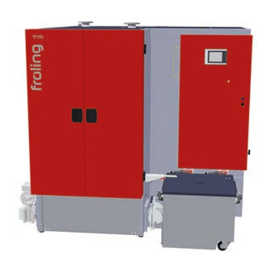
Lambdatronic H 3200 - Turbomat
Core module version 55.04 - Build 05.21 | Touch contol version 60.01 Build 01.39
Translation of original German version of service handbook for technicians.
Read and follow all instructions and safety instructions.
All errors and omissions excepted.
B1840023_en | Edition 21/03/2024
Advertisement
Table of Contents


Need help?
Do you have a question about the Lambdatronic H 3200 and is the answer not in the manual?
Questions and answers