Fröling Lambdatronic H 3200 Service Manual
For wood chip boiler
Hide thumbs
Also See for Lambdatronic H 3200:
- Service handbook (116 pages) ,
- Service manual (134 pages) ,
- Service handbook (116 pages)
Table of Contents
Advertisement
Quick Links
Service manual
Lambdatronic H 3200 for wood chip boiler
Core module version 50.04 - Build 05.19 | Touch control version 60.01 - Build 01.37
Translation of the original German installation instructions for technicians
Read and follow the instructions and safety information!
Technical changes, typographical errors and omissions reserved!
B1480721_en | Edition 12/08/2021
Froling GesmbH | A-4710 Grieskirchen, Industriestraße 12 | www.froeling.com
Advertisement
Table of Contents

Related Manuals for Fröling Lambdatronic H 3200


Summary of Contents for Fröling Lambdatronic H 3200
- Page 1 Service manual Lambdatronic H 3200 for wood chip boiler Core module version 50.04 - Build 05.19 | Touch control version 60.01 - Build 01.37 Translation of the original German installation instructions for technicians Read and follow the instructions and safety information!
-
Page 2: Table Of Contents
Table of contents 3.1.2 Check on the connected units 1 General 3.1.3 System check 3.2 General information about the settings 1.1 About these instructions wizard 1.2 Safety information 3.3 Switching on for the first time 2 Power connection and wiring 3.4 Starting the setting wizard 2.1 Core module and connection options 4 Parameters overview... - Page 3 5.7.2 Carrying out a software update on the Set - Cleaning touch control Setting - Combustion chamber 5.7.3 Finishing a software update Setting - Lambda values Set - Lambda probe Service manual Lambdatronic H 3200 for wood chip boiler | B1480721_en...
- Page 4 Table of contents 5.8 USB data recording 7.1 Addresses 7.1.1 Address of manufacturer Customer service 6 Notes 7.1.2 Address of the installer 7 Appendix Froling GesmbH | A-4710 Grieskirchen, Industriestraße 12 | www.froeling.com...
-
Page 5: General
❒ Insulate the flue gas pipes and do not touch them during operation The information on safety, standards and guidelines in the assembly and operating instructions for the boiler should also be observed! Service manual Lambdatronic H 3200 for wood chip boiler | B1480721_en... -
Page 6: Power Connection And Wiring
Power connection and wiring Core module and connection options 2 Power connection and wiring 2.1 Core module and connection options 2.1.1 Board view - core module KM-36 (Optionsmodul) KM-02 KM-01 (Bus) (Bus) KM-35 End jumper (Betriebssignal) KM-03 (Bus) KM-34 (Heizkreispumpe 0 KM-04 Core module oder Brennerrelais) - Page 7 Pump 1 Connection cable 3 x 1.5 mm , max. 1.5A / 280W / 230V KM-29 Mains connection Connection cable 3 x 1.5 mm , fuse provided by customer: C16A Service manual Lambdatronic H 3200 for wood chip boiler | B1480721_en...
-
Page 8: Mains Connection
Power connection and wiring Core module and connection options Connection / Name Note KM-30 Mixing valve heating circuit 2 Connection cable 4 x 0.75 mm , max. 0.15A / 230V KM-31 Mixing valve heating circuit 1 KM-32 Heating circuit pump 2 Connection cable 3 x 1.5 mm , max. -
Page 9: Fra Room Temperature Sensor
Allows you to adjust the temperature by +/- 3°C IMPORTANT! Refer to the supplied assembly instructions for more detailed explanations on connecting and operating the FRA room temperature sensor. Service manual Lambdatronic H 3200 for wood chip boiler | B1480721_en... -
Page 10: Boiler Enable Contact
(Heizkreispumpe 1) KM-32 (Heizkreispumpe 2) Power connection and wiring KM-31 Core module and connection options (Mischer 1) nde) 2.1.5 Boiler enable contact KM-30 (Mischer 2) ...) When commissioning the boiler using the settings wizard, the boiler release contact function (“How is the 5V/P3 boiler release contact on the core module being used?”) is called up to enable the optional KM-29... - Page 11 30%). FRKEM29 AO-P1 ❒ Connect pump to output “Pump 1” of the core module ❒ In the relevant menu, set the pump control to “Pump without control signal” Service manual Lambdatronic H 3200 for wood chip boiler | B1480721_en...
-
Page 12: Connecting An Isolating Valve To The Core Module
Power connection and wiring Core module and connection options 2.1.7 Connecting an isolating valve to the core module If an isolating valve is connected to the speed-controlled pump outlet, an RC element must be used. FRKEM29 AO-P1 ❒ Phase (L) for switching the valve and connecting neutral conductor (N) to output “Pump 1” with the RC element ❒... -
Page 13: Heating Circuit Pump 0 / Burner Relay
“Standby relay” output in the “Manual” -> “Digital outputs” menu. Operating status Relay status Boiler off, standby, fault All other operating statuses (e.g. preparation, heating up, pre-heating, ignition, heating, slumber, cleaning, shutdown wait 1, shutdown wait 2, etc.) Service manual Lambdatronic H 3200 for wood chip boiler | B1480721_en... -
Page 14: Expansion Modules
Power connection and wiring Expansion modules 2.2 Expansion modules 2.2.1 Heating circuit module Two heating circuits can be controlled as standard with the core module. To add further heating circuits, the heating circuit module boards must be expanded. Expansion can include up to eight heating circuit modules (address 0 to 7). -
Page 15: Hydraulic Module
Pump outlets on board. The correct pump designation is determined by the set HY-15 Pump _.2 module address (0-7). Example: module address “2” = pump 2.1 and pump 2.2 1. YMM as per ÖVE-K41-5 or H05VV-F as per DIN VDE 0881-5 Service manual Lambdatronic H 3200 for wood chip boiler | B1480721_en... -
Page 16: Connecting A Circulating Pump To The Hydraulic
Power connection and wiring Expansion modules Hydraulic module – Version FRHYU22 End jumper HY-01 Hydraulic module HY-02 FRHYU22 (Bus) Mains fuse Module address HY-03 / HY-04 HY-13 HY-14 HY-15 (Bus) (Netz) (Pumpe _.1) (Pumpe _.2) Connection / Name Note HY-01 Patch cable CAT 5 RJ45 SFTP 1:1 configuration;... - Page 17 ➥ Make sure that the cables are configured correctly (polarity) in accordance with the connection diagram of the pump! ❒ Set control of the pump in the relevant menu to “Field pump / PDM” or “Field pump / 0-10V” Service manual Lambdatronic H 3200 for wood chip boiler | B1480721_en...
- Page 18 Power connection and wiring Expansion modules High efficiency pump without control signal It is possible to control the speed when using this type of pump. The use of a line regulating valve (e.g.: Setter balancing valve) is recommended. up to hydraulic module version FRHYU21 up to hydraulic module version FRHYU22 21 11 24 14...
- Page 19 ❒ Connect power supply at pump connector ❒ In relevant menu, set pump to “Field pump PDM + valve” or “Field pump 0-10V + valve” Service manual Lambdatronic H 3200 for wood chip boiler | B1480721_en...
-
Page 20: Connecting An Isolating Valve To The Hydraulic
Power connection and wiring Expansion modules Connecting an isolating valve to the hydraulic module CAUTION! As of module version FRHYU22, one relay output is available at each of the pump outlets in addition to the triac output. Observe the following connection diagrams for the correct wiring. up to hydraulic module version FRHYU21 up to hydraulic module version FRHYU22 FRHYU22... -
Page 21: Wood Chip Module
T4 24-50 Connection cable 3 x 1.5 mm condenser HG-14 WOS drive Connection cable 3 x 1.5 mm HV cleaning HG-15 Electric ignition Use connection cable of the component Service manual Lambdatronic H 3200 for wood chip boiler | B1480721_en... - Page 22 Power connection and wiring Expansion modules Connection / Name Note HG-16 Mains connection Connection cable 5 x 2.5 mm ; 400 VAC HG-17 Feed screw Connection cable 4 x 1.5 mm ; max. 0.75kW / 400V T4e 20-175 Combi drive T4e 200-350 HG-18 Stoker screw...
-
Page 23: Plug Power Pack Frsnt17
24 V power supply Connection cable 2 x 1.0 mm², max. 2A 1. YMM as per ÖVE-K41-5 or H05VV-F as per DIN VDE 0881-5 Fuses 2 AT Fuses for 24V outputs Service manual Lambdatronic H 3200 for wood chip boiler | B1480721_en... -
Page 24: Plug Power Pack Meanwell Lrs-100-24
Power connection and wiring Expansion modules 2.2.5 Plug power pack Meanwell LRS-100-24 +24V +24V Connection / Name Note LRS-01 Mains Connection cable 3 x 1.5 mm² LRS-02 24 V power supply 2 outputs, max. 4.5A Connection cable 2 x 1.0 mm² 1. -
Page 25: Analogue Module
On T4e with 2 HV modules, a different input must be used to use the external power specification. The input is set in the “Boiler - General settings” menu accordingly. Actual current HV module 2 T4e 300/350 Position feedback of primary air flap Service manual Lambdatronic H 3200 for wood chip boiler | B1480721_en... -
Page 26: External Power Demand
Power connection and wiring Expansion modules Output Designation TX 200/250 Induced draught control Target voltage HV module 1 Target current HV module 1 Target voltage HV module 2 Actual current HV module 2 T4e 300/350 Position feedback of primary air flap Standard configuration –... -
Page 27: Digital Module
Output Designation Discharge expansion Discharge screw forward cabinet at T4 24-110 and Discharge screw back TX 150 Rotary valve forward Rotary valve back Intermediate screw forward Intermediate screw back Service manual Lambdatronic H 3200 for wood chip boiler | B1480721_en... - Page 28 Power connection and wiring Expansion modules Standard configuration – Digital module with address 1 Input Designation TX 250 Boiler loading pump motor protection switch TI 350 Grate motor protection switch TX 250 Combustion air fan motor protection switch TI 350 Pump slide-on duct cooling fault TX 250 Induced draught fan motor protection switch...
- Page 29 PT4e suction system MAX level sensor Sliding floor discharge Hydraulic oil temperature unit Sliding floor discharge Hydraulic chamber key switch unit Sliding floor discharge Safety limit switch unit Service manual Lambdatronic H 3200 for wood chip boiler | B1480721_en...
- Page 30 Power connection and wiring Expansion modules Input Designation PT4e suction system Induced draught fan safety relay Sliding floor discharge Light scanner 1 unit Sliding floor discharge Light scanner 2 unit Output Designation Sliding floor discharge Sliding floor on unit PT4e suction system Suction turbine on Sliding floor discharge Star-delta start-up 1...
-
Page 31: Feed System Module
Mains Connection cable 5 x 2.5 mm AU-15 Output 2 Connection cable 4 x 1.5 mm , max. 0.75kW -7 400V (e.g. connecting a feed screw) AU-16 Output 1 Service manual Lambdatronic H 3200 for wood chip boiler | B1480721_en... - Page 32 Power connection and wiring Expansion modules Connection / Name Note AU-15 Fuses T3, 15A AU-22 1. YMM as per ÖVE-K41-5 or H05VV-F as per DIN VDE 0881-5 Froling GesmbH | A-4710 Grieskirchen, Industriestraße 12 | www.froeling.com...
-
Page 33: Bus Connection
A voltage supply unit must be used for every touch room console (heating circuit module, hydraulic module). Service manual Lambdatronic H 3200 for wood chip boiler | B1480721_en... -
Page 34: Connecting The Bus Cable
Power connection and wiring BUS connection 2.3.1 Connecting the bus cable For the bus connections between the individual modules, cable type LIYCY paired 2x2x0.5 should be used. The connection to the 5-pin plugs should be carried out according to the following diagram: Braided shield Braided shield white... -
Page 35: Setting The Module Address
4.1 – 4.2 13 – 14 5.1 – 5.6 5.1 – 5.2 15 – 16 6.1 – 6.6 6.1 – 6.2 17 – 18 7.1 – 7.6 7.1 – 7.2 Service manual Lambdatronic H 3200 for wood chip boiler | B1480721_en... -
Page 36: Potential Equalisation / Potential Separation
Power connection and wiring BUS connection 2.3.4 Potential equalisation / potential separation There can be potential shifts between buildings. In this case, equalising currents flow via the bus connection shield which can damage the modules. To prevent this, buildings must be connected using a potential equalisation conductor. BUS connection Expansion module... -
Page 37: Connection Information According To Pump Types
Connect the control cable to the PDM output on the board, making sure that the polarity is correct: - brown wire to earth - white wire to plus Do not use the other two wires (blue, black) and insulate Service manual Lambdatronic H 3200 for wood chip boiler | B1480721_en... -
Page 38: Frequency Converter
Power connection and wiring Frequency converter 2.5 Frequency converter Below is a description of how the input elements of the frequency converter basically work. 2.5.1 Operating elements Name Description Escape Go back one step in the program menu. Cancel changes to a parameter value and exit program mode Select button Go forward one step in the program menu. -
Page 39: Changing Parameters
TIP: Pressing the Sel button allows you to change the tens column, pressing it again allows you to change the hundreds column Confirm the set value by pressing Enter Press Escape several times to exit the program menu Service manual Lambdatronic H 3200 for wood chip boiler | B1480721_en... - Page 40 Power connection and wiring Frequency converter Completing the parameter settings After setting the parameters, you must restart the frequency converter to apply the new settings. NOTICE Malfunctions after setting parameters! If the frequency converter becomes inoperable after setting the required parameters: ❒...
-
Page 41: Initial Start-Up With Settings Wizards
Check for loose or uninsulated wires in the terminal boxes of the pumps, mixing valve and switch valve, which could cause a short-circuit 3.1.3 System check ❒ Check that the main fuse for the boiler has a sufficient rated amperage ⇨ See "Mains connection" [page 8] Service manual Lambdatronic H 3200 for wood chip boiler | B1480721_en... -
Page 42: General Information About The Settings Wizard
Initial start-up with settings wizards General information about the settings wizard 3.2 General information about the settings wizard A wide variety of setting wizards are available to start-up the boiler system. A small selection of these can be found on the “Customer” operating level in the “Quick menu”; the rest are only on the “Service” operating level. The settings wizards can be used to set various sections of the boiler system (boiler, lambda probe, hydraulic system, etc.) with guided queries of the controller. -
Page 43: Switching On For The First Time
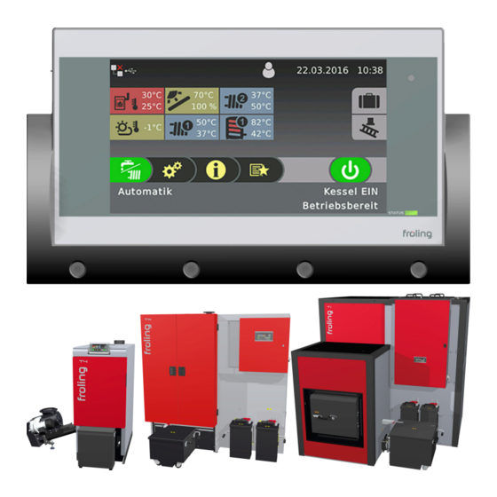
Then the basic screen of the touch display is shown. 1: Selection of the controller language 2: Setting the production number (see identification plate) 3: Setting the date and time 4: Display of the basic screen Service manual Lambdatronic H 3200 for wood chip boiler | B1480721_en... -
Page 44: Starting The Setting Wizard
Initial start-up with settings wizards Starting the setting wizard 3.4 Starting the setting wizard 1: Tap the icon to change the user level 2: Type in the service code and confirm 3: Tap the icon of the settings wizard 4: Tap the “Boiler” setting wizard 5: The settings wizard loads 6: Read the information text and continue with “YES”... - Page 45 Field pump 0-10 V + valve Solar pump 0-10 V + valve Switch valve ⇨ See "Activation options of pump outlets" [page 124] Continue to the next step Go back one step Service manual Lambdatronic H 3200 for wood chip boiler | B1480721_en...
-
Page 46: Parameters Overview
Parameters overview Heating 4 Parameters overview 4.1 Heating 4.1.1 Heating - Status System menu Heating Heating circuit mode Actual flow temperature Display and setting the heating circuit mode: Display of the current flow temperature. Auto: Flow temperature setpoint Automatic: heating phases according to the set heating times Display of the calculated flow temperature setpoint. -
Page 47: Heating - Temperatures
▪ underfloor heating: 2-3 assigned to a high temperature heating circuit (e.g. ▪ Radiators (new build): 4-5 radiators). ▪ Radiators (old build): 6-7 NOTICE! Observe external influences on the remote control! Service manual Lambdatronic H 3200 for wood chip boiler | B1480721_en... -
Page 48: Heating - Times
Parameters overview Heating 4.1.3 Heating - Times System menu Heating ⇨ See "Setting times" [page 133] 4.1.4 Heating - Service System menu Heating Heating circuit pump Should this heating circuit heat when there is DHW tank priority? Used for testing the pump output: ▪... -
Page 49: Heating - Heating Up Program
If the current room temperature falls below the set frost protection temperature setpoint, this influences the set flow temperature setpoint of the heating up program. NOTE: Only in conjunction with remote control! Service manual Lambdatronic H 3200 for wood chip boiler | B1480721_en... -
Page 50: Heating Up Programs
Parameters overview Heating Heating up programs Heating up program 1: Heating up program 2: Heating up program 5: Heating up program 6: Heating up program 3: Heating up program 4: Heating up program 7: The heating up programs listed are non-binding recommendations. -
Page 51: Heating - General Settings
– Contact of room thermostat open: Heating circuit pump deactivated, mixing valve is closed – Contact of room thermostat closed: Heating circuit pump and mixer control active Service manual Lambdatronic H 3200 for wood chip boiler | B1480721_en... -
Page 52: Water
Parameters overview Water 4.2 Water 4.2.1 Water - Status System menu Water DHW tank top temperature DHW tank bottom temperature Current temperature of the DHW tank. If the time window Prerequisite: Solar panel system is regulated by Froling! for DHW tank loading is reached and the temperature falls Current temperature in the area of the reference sensor of below the value set under parameter “Reload if DHW the solar panel system. -
Page 53: Water - Times
Control of DHW tank pump Definition of control signal for pump type used. ⇨ See "Activation options of pump outlets" [page 124] Service manual Lambdatronic H 3200 for wood chip boiler | B1480721_en... - Page 54 Parameters overview Water Minimum DHW tank speed Maximum DHW tank pump speed Adjustment of the minimum speed to the pump type (set If you need to limit the maximum speed of the boiler mode of pump in accordance with pump manufacturer). loading pump for systemic reasons, you can do so by adjusting this parameter.
-
Page 55: Solar
The yields of the last 6 days are available. Total yield [kWh] Display of the heat quantity which has been supplied by the solar panel system since activation of the heat meter. Service manual Lambdatronic H 3200 for wood chip boiler | B1480721_en... -
Page 56: Solar - Temperatures
Parameters overview Solar 4.3.2 Solar - Temperatures System menu Solar Boiler target temperature during solar charging Heat exchanger - buffer tank pump start delay Up to this temperature the DHW tank is heated by the Prerequisite: Hydraulic system 12 or 13 solar system. -
Page 57: Solar - Times
Maximum collector pump speed If you need to limit the maximum speed of the collector pump for systemic reasons, you can do so by adjusting this parameter. Service manual Lambdatronic H 3200 for wood chip boiler | B1480721_en... - Page 58 Parameters overview Solar For solar to store and DHW tank, the DHW tank has Control of storage tank – heat exchanger pump priority Prerequisite: Hydraulic system 12 or 13 ▪ YES: The DHW tank is loaded until the temperature set Definition of control signal for pump type used.
-
Page 59: Solar - Heat Meter
Is an external flow through counter used Shows the historical progression of the solar panel system. ▪ YES: An external volume pulse transmitter is in use. The yields of the last 6 days are available. Service manual Lambdatronic H 3200 for wood chip boiler | B1480721_en... -
Page 60: Buffer Tank
Parameters overview Buffer tank 4.4 Buffer tank 4.4.1 Buffer tank - Status System menu Buffer tank Buffer tank top temperature Buffer tank pump control Display of the current temperature in the top part of the Display of the current speed of the buffer loading pump. buffer tank. -
Page 61: Buffer Tank - Temperatures
If this difference is not system 4 reached, the storage tank loading stops. If the buffer tank charge is greater than the specified value, the boiler system follows the shutdown procedure. Service manual Lambdatronic H 3200 for wood chip boiler | B1480721_en... -
Page 62: Buffer Tank - Times
Parameters overview Buffer tank 4.4.3 Buffer tank - Times System menu Buffer tank ⇨ See "Setting times" [page 133] 4.4.4 Buffer tank - Service System menu Buffer tank Enable heating circuit pump 0 according to top buffer Sensor input of storage tank top sensor temp. - Page 63 ▪ YES: If the valve switches incorrectly, the way it is storage tank, but all of the storage tanks in sub-stations. controlled can be changed using this parameter. This increases the runtime related to a boiler system start. Service manual Lambdatronic H 3200 for wood chip boiler | B1480721_en...
-
Page 64: Boiler
Parameters overview Boiler 4.5 Boiler 4.5.1 Boiler - Status System menu Boiler Boiler temperature Position of primary air flap Display of the current boiler temperature. Display of the current position of the primary air flap (adjusted for the air settings). Flue gas temperature Residual oxygen content Display of the current flue gas temperature. -
Page 65: Boiler - Temperatures
Waiting time for calculating the return temperature setpoint The quick regulation responds to this temperature increase adjustment. Once the specified time has passed, the within the set monitoring time. heating system temperatures are evaluated. Service manual Lambdatronic H 3200 for wood chip boiler | B1480721_en... -
Page 66: Boiler - Times
Parameters overview Boiler Monitoring time of temperature rise in return Monitoring time of temperature rise in return (for start of quick regulation). 4.5.3 Boiler - Times System menu Boiler ⇨ See "Setting times" [page 133] 4.5.4 Boiler - Service System menu Boiler Variable mode activated Control of boiler loading pump... -
Page 67: Boiler - General Settings
The boiler is only functional again once it has continues to run. been recommissioned by Froling customer services or ▪ YES: The service hours counter since last maintenance authorized installer. is set to “0”. Service manual Lambdatronic H 3200 for wood chip boiler | B1480721_en... -
Page 68: Boiler - General Settings - Modbus Settings
Parameters overview Boiler Analogue module input for external power demand Defines the input for the external power demand with a specified power of “0-10V“ (address of analogue module and input terminal, e.g. 0.3). Boiler - General settings - MODBUS settings MODBUS settings System menu... -
Page 69: Boiler 2 - Status
If the secondary boiler is started, it will run for at least the boiler is switched off and whether the standby boiler is length of time set here. activated immediately on request. Service manual Lambdatronic H 3200 for wood chip boiler | B1480721_en... -
Page 70: Boiler 2 - Service
Parameters overview Boiler 2 No heat pump operation when outside air temperature less Minimum temperature of secondary boiler than When the secondary boiler reaches the specified Prerequisite: Heat pump as standby boiler temperature, the loading pump is started and switches the isolating valve. -
Page 71: Fuel
During troubleshooting of feed screw, it turns forwards for Forced infeed maximum runtime Duration, how long should the feed screw turn forwards during troubleshooting. Maximum duration of forced infeed. The screw then pauses. Service manual Lambdatronic H 3200 for wood chip boiler | B1480721_en... -
Page 72: Feed System - Screw 2 On Lb
Parameters overview Feed system Forced infeed attempts Minimum current monitoring active If the light barrier still does not come down after the set Indicates whether the minimum current is being monitored number of forced infeeds, an error message will be issued. during operation. -
Page 73: Feed System - Rotary Agitator
“Weighting of screw runtime when bunker is EMPTY” parameter. Service manual Lambdatronic H 3200 for wood chip boiler | B1480721_en... -
Page 74: Discharge - Cyclone 1 (Feed System-Configuration 8)
Parameters overview Feed system 4.8.4 Discharge - Cyclone 1 (feed system-configuration 8) Cyclone 1 System menu Discharge Cyclone active Maximum time until switching of probe ▪ NO: Cyclone on the vacuum discharge system is not in Prerequisite: Feed system 4 probe switch or 8 probe use. - Page 75 Address at which the screw has been connected. Service hours of suction screw Prerequisite: Large-scale suction system with one cyclone and 2 rotary valves. operating hours of suction screw discharge on a GASS. Service manual Lambdatronic H 3200 for wood chip boiler | B1480721_en...
-
Page 76: Feed System - Cyclone 1 (Suction Screw)
Parameters overview Feed system 4.8.5 Feed system - Cyclone 1 (suction screw) Cyclone 1 / 2 System menu Feed system Cyclone active Screw cycle ▪ NO: Cyclone on the vacuum discharge system is not in Discharge screw runtime, minus an adjustable pause time. use. -
Page 77: Feed System - Cyclone 1 (4/8X Toggle)
Probe suction reversal for Prerequisite: RS4 / RS8 pellet suction system Before switching to the next probe, the probe that was last used is back-flushed for the time set. Service manual Lambdatronic H 3200 for wood chip boiler | B1480721_en... -
Page 78: Feed System - Cyclone
Parameters overview Feed system Suction run-on Suction turbine operating hours When the fill level sensor detects fuel in the cyclone, the Counter for the operating hours of the suction turbine. suction turbine remains active for the time set. Is position 1 ... 8 of the change-over unit being used? To enable/disable the individual suction positions of the RS4 / RS8 suction system. - Page 79 The default vibration interval timing is 60%: that feeds the cyclone. Time basis: 100 sec. → 60 sec. on / 40 sec. pause Inputs Displays the current operation of the inputs. Service manual Lambdatronic H 3200 for wood chip boiler | B1480721_en...
-
Page 80: Network Pump
Parameters overview Network pump 4.9 Network pump 4.9.1 Network pump - Status System menu Network pump Network return temperature Return temperature distributor 2 … 4 Display of the current return temperature of the remote Prerequisite: Variant 2 or variant 3 and pump for distributor line. -
Page 81: Network Pump - Service
Control of distributor 1 pump Prerequisite: Variant 1 and pump for distributor 1 installed Definition of control signal for pump type used. ⇨ See "Activation options of pump outlets" [page 124] Service manual Lambdatronic H 3200 for wood chip boiler | B1480721_en... -
Page 82: Cascade
Parameters overview Cascade 4.10 Cascade 4.10.1 Cascade - Status System menu Cascade Buffer tank charge Display of the current buffer tank charge. 4.10.2 Cascade - Backup boiler Slave boiler 1 System menu Cascade Slave boiler boiler temperature Slave boiler control variable Display of the current boiler temperature of the backup Display of the signal for the combustion controller. -
Page 83: Cascade - Temperatures
If the storage tank charge is lower than this value, slave boilers 3 and 4 are started. Boiler temperature setpoint Storage tank charge status CS [%] Storage tank charge status CS [%] Service manual Lambdatronic H 3200 for wood chip boiler | B1480721_en... -
Page 84: Cascade - Service
Parameters overview Cascade Quick start if buffer tank discharge is greater than (% / Reduce the overall output of the cascade before the 10min)] storage tank is fully charged If the storage tank discharge is greater than the set value When the storage tank charge exceeds the value which is within 10 minutes, the boiler with the greatest rated heat set under “Start point 1 at storage tank... -
Page 85: Difference Regulator
When the heat sink reaches this value, the pump of the If the temperature difference between the heat source and differential controller is deactivated. the heat sink falls below this value, the pump of the differential controller is deactivated. Service manual Lambdatronic H 3200 for wood chip boiler | B1480721_en... -
Page 86: Difference Regulator - Times
Parameters overview Difference regulator 4.11.3 Difference regulator - Times System menu Diff. control ⇨ See "Setting times" [page 133] 4.11.4 Difference regulator - Service System menu Diff. control Pump output of diff. control pump Sensor input of heat source sensor Pump outlet to which the pump of the differential controller Sensor input to which the heat source sensor is is connected. -
Page 87: Circulation Pump
If the set temperature at the return circulation line is reached, the circulation pump will be deactivated. NOTICE! Parameter only relevant when using a return feed sensor in the circulation line! Service manual Lambdatronic H 3200 for wood chip boiler | B1480721_en... -
Page 88: Circulation Pump - Times
Parameters overview Circulation pump 4.12.3 Circulation pump - Times System menu Circ. Pump ⇨ See "Setting times" [page 133] 4.12.4 Circulation pump - Service System menu Circ. Pump Sensor input of circulation return sensor Control of circulation pump Sensor input to which the sensor at the return line of the Definition of control signal for pump type used. -
Page 89: Manual
Bunker filling rotary agitator ▪ ON: In the case of rotary agitator with a separate drive system, the head of the rotary agitator is operated separately from the delivery screw. Service manual Lambdatronic H 3200 for wood chip boiler | B1480721_en... -
Page 90: Manual - Digital Outputs
Parameters overview Manual 4.13.2 Manual - Digital outputs Digital outputs System menu Manual The parameters displayed depend on the boiler configuration! ▪ A 0: Automatic, Off; A 1: Automatic, On ▪ 1: Manual, On ▪ 0: Manual, Off 4.13.3 Manual - Analogue outputs Analogue outputs System menu Manual... -
Page 91: Manual - Digital Inputs
Digital inputs System menu Manual The parameters displayed depend on the boiler configuration! ▪ A 0: Automatic, Off; A 1: Automatic, On ▪ 1: Manual, On ▪ 0: Manual, Off Service manual Lambdatronic H 3200 for wood chip boiler | B1480721_en... -
Page 92: System
Parameters overview System 4.14 System 4.14.1 System - Settings Setting - Boiler temperature Boiler temperature System menu System Setting ⇨ See "Boiler - Temperatures" [page 65] Setting - Slide-on duct Slide-on duct System menu System Setting Slide-on duct temperature Maximum permitted temperature in the slide-on duct/burn through elbow Display of the current reference temperature for the cooling of the slide-on duct and burn through elbow. -
Page 93: Setting - Flue Gas
When the flue gas temperature rises by the value set here during “Pre-heating” or “Ignition” status, the boiler controller switches to “Heating” status. Service manual Lambdatronic H 3200 for wood chip boiler | B1480721_en... - Page 94 Parameters overview System Flue gas Setting FGR characteristics Reduce underpressure at 100% FGR by The FGR characteristics is used to define the progression A certain value is deducted from the underpressure of the flue gas recirculation section. Depending on the setpoint depending on the FGR flap position.
- Page 95 FGR flap control delay time deactivated again. During pressure changes in the FGR duct, the control of the FGR flap is delayed by the specified time, in order to counter act constant vibrations. Service manual Lambdatronic H 3200 for wood chip boiler | B1480721_en...
- Page 96 Parameters overview System Maximum permitted pressure deviation FGR cleaning duration Defines the tolerance range for the specified pressure Specifies the duration for the automatic cleaning of the setpoint in the FGR duct. If the actual value remains above FGR duct in seconds. or below the pressure setpoint for the duration of the delay time (parameter “Delay till warning”), a warning message FGR cleaning at CCT...
- Page 97 ▪ Status "3": Temperature box error ▪ Status "4": High voltage error ▪ Status "5": Wait for ready-to-measure state ▪ Status "6": Values critical ▪ Status "7": Measure ▪ Status "8": Measuring mode error Service manual Lambdatronic H 3200 for wood chip boiler | B1480721_en...
- Page 98 Parameters overview System Service E-filter function active Is there a siphon fitted? Used to activate/deactivate the electrostatic filter function. By default this parameter is set to “YES” and cleaning of When the filter is deactivated, the bypass flap is open and the filter is performed according to the specified interval.
- Page 99 Number of HV modules Used to activate/deactivate the electrostatic filter function. Specifies the number of HV modules used. One or two modules are used, depending on the output of the boiler. Service manual Lambdatronic H 3200 for wood chip boiler | B1480721_en...
- Page 100 Parameters overview System Max. output HV modules Cleaning active during heating a further pause of 15 seconds the HV modules are For setting the output power in watts of the HV module switched on again. used. If two modules are used, the output of one module IMPORTANT: For the cleaning after switching off the must be set here.
-
Page 101: Setting - Ignition
Feed time until a sufficient quantity of fuel is present on the Time during which only the ignition is activated. The fuel combustion grate to carry out the ignition process. slide-in is not active for this duration. Service manual Lambdatronic H 3200 for wood chip boiler | B1480721_en... -
Page 102: Setting - Air Settings
Parameters overview System Infeed during ignition Infeed time without ignition Material feed in “Ignition“ status. Specifies how long fuel is fed to the combustion grate before “Pre-heating” operating status. Maximum ignition duration Infeed during ignition Specifies how long the ignition procedure should last. “Heating”... - Page 103 CCT". For the start of cooling you should ensure that the secondary air does not begin at 0, but at the current (oxygen managed) secondary air setting. Service manual Lambdatronic H 3200 for wood chip boiler | B1480721_en...
-
Page 104: Setting - Fuel Slide-In
Parameters overview System Setting - Fuel slide-in Fuel slide-in System menu System Setting Maximum value for automatic max. fuel feed-in Infeed during ignition Upper limit for the automatic fuel feed-in. Defined fuel feed-in for the “Ignition” status duration. Minimum value for automatic max. fuel feed-in Activation delay for slide-in Lower limit for the automatic fuel feed-in. - Page 105 Nominal current for feed screw the overcurrent sensor of the rotary valve activates. Setting the nominal current of the feed screw according to the identification plate on the motor. Service manual Lambdatronic H 3200 for wood chip boiler | B1480721_en...
- Page 106 Parameters overview System Min. current monitoring with stoker Cycles of sliding floor after ▪ YES: A failure of measured phase is detected. Prerequisite: Feed system, sliding floor available If the transverse conveyor screw runs for this time without Min. current monitoring with feed screw the sliding floor being requested, the sliding floor is activated for a set time (“Duration of cycles of ▪...
-
Page 107: Setting - Vibration / Wos / Cleaning
Second start of cleaning Clean after how many shutdowns Cleaning starts at this time. This parameter defines the number of shutdowns after which the cleaning cycle is carried out. Service manual Lambdatronic H 3200 for wood chip boiler | B1480721_en... -
Page 108: Setting - Wos / Cleaning
Parameters overview System Primary air at the start of heating-cleaning (absolute) During troubleshooting of ash screw, it turns backwards for The primary air is regulated to this value at the start of the Specifies how long the ash screw should turn in the boiler status “heating - cleaning”... -
Page 109: Set - Cleaning
▪ NO: In “Cleaning” operating status, the combustion carried while the ash screw is blocked. Once the specified grate is tipped and cleaned. number has been reached, no further start process is permitted Service manual Lambdatronic H 3200 for wood chip boiler | B1480721_en... -
Page 110: Setting - Combustion Chamber
Parameters overview System Setting - Combustion chamber Combustion chamber System menu System Setting Under-pressure in the boiler at maximum output Minimum combustion chamber temperature At maximum boiler output the specified underpressure has Defines the minimum combustion chamber temperature in to be kept. heating status. - Page 111 Start of slide-in reduction from cc temp signal When the combustion chamber temperature signal reaches the specified value, the fuel slide-in is reduced. Service manual Lambdatronic H 3200 for wood chip boiler | B1480721_en...
-
Page 112: Setting - Lambda Values
Parameters overview System Setting - Lambda values Lambda values System menu System Setting Heating up time for lambda probe O2 Controller max Time for the heating up cycle of the lambda probe. Adjustable parameters for the residual oxygen controller. NOTICE! Factory setting - do not change! Residual oxygen content setpoint Slide-in control Residual oxygen content which is regulated during... -
Page 113: Set - Lambda Probe
Lambda probe calibration (probe must be at 21% O2) ▪ YES: After activation of the Lambda probe heating, the Lambda probe can be calibrated. ▪ NOTICE! The Lambda probe must be at 21% oxygen (air)! Service manual Lambdatronic H 3200 for wood chip boiler | B1480721_en... - Page 114 Parameters overview System Switching-type sensor Lambda values Switching-type sensor Setting Residual oxygen content Lambda probe voltage corrected Display of the current residual oxygen content. Display of the measured Lambda probe voltage, at which the “Lambda probe correction value” is taken into Lambda probe voltage measured account.
-
Page 115: Set - Quantity Of Heat Calculation
System menu System Setting ⇨ See "Boiler - General settings" [page 67] MODBUS settings MODBUS General settings settings Setting ⇨ See "Boiler - General settings - MODBUS settings" [page Service manual Lambdatronic H 3200 for wood chip boiler | B1480721_en... -
Page 116: System - Current Values
Parameters overview System 4.14.2 System - Current values System menu System Current values Display of the current value for the relevant parameter. The parameters displayed depend on the boiler configuration! Operation hours Operation hours System menu System Current values Display of the current number of operation hours of the respective unit and respective components. -
Page 117: System - Sensors And Pumps
The number of parameters depends on the configuration. 4.14.4 System - System selection System menu System System selection Menu for setting the configuration for systems that have not been configured with the setting wizard. Service manual Lambdatronic H 3200 for wood chip boiler | B1480721_en... -
Page 118: Diagnostics
Parameters overview Diagnostics 4.15 Diagnostics 4.15.1 Diagnosis – Current fault list Current fault list System menu Diagnostics Display of the current fault messages. In addition, you can also invoke time information here, such as when the fault occurred, when the fault was acknowledged and when the fault was cleared. -
Page 119: Diagnostics - Clear Error History
Clear error history System menu Diagnostics The entire error history can be deleted using this function. From this time on, the error history will be filled again with new fault messages. Service manual Lambdatronic H 3200 for wood chip boiler | B1480721_en... -
Page 120: Touchscreen
Parameters overview Touchscreen 4.16 Touchscreen 4.16.1 Touchscreen - Display settings Display settings - General General System menu Touchscreen Display settings Brightness Module address Display of the light sensor’s evaluation of the current This is where you can change the module address if it is brightness in the room for adjusting the backlight. -
Page 121: Display Settings - Basic Display
(e.g. when replacing the core ⇨ See "Software update Lambdatronic 3200" [page 137] module). Restart display Touch control unit is restarted and the data is reloaded from the core module. Service manual Lambdatronic H 3200 for wood chip boiler | B1480721_en... -
Page 122: Touchscreen - Display Operating Rights
Parameters overview Touchscreen 4.16.2 Touchscreen - Display operating rights System menu Touchscreen Display operating rights In this menu the operating rights for the individual room consoles are allocated. If access from a room console to a heating system component is permitted, the corresponding parameter must be set to “YES”. -
Page 123: Touchscreen - Display Allocation
DHW tank number with its address must set on set on the room console. The parameters are set to “none” the room console. The parameters are set to “none” at the at the factory! factory! Service manual Lambdatronic H 3200 for wood chip boiler | B1480721_en... -
Page 124: Faq
Activation options of pump outlets 5 FAQ 5.1 Activation options of pump outlets Pump 0.1 – 7.2, pump 1 The following settings are possible at the hydraulic modules as well as at pump 1 on the core module with pump outlets 0.1 –... -
Page 125: Boiler Operating Statuses
“Shutdown wait” status and “Tilt grate”. It will remain in this status for at least 30 mins depending on the boiler output, the fuel used and the parameters set. Service manual Lambdatronic H 3200 for wood chip boiler | B1480721_en... -
Page 126: Determination Of The Quantity Of Heat
Determination of the quantity of heat 5.3 Determination of the quantity of heat 5.3.1 Assembly Information The contact sensor and the line regulating valve must be positioned in the direction of flow downstream of the circulating pump and immediately upstream of the return connection of the boiler. Additional contact sensors and line regulating valves are required for boilers without return temperature control or return temperature control with thermal valve. -
Page 127: Setting The Type Of Heat Quantity Calculation
❒ Go to the menu “System → Settings → Boiler heat quantity calculation” ❒ Enter the recorded values for the flow of the circulating pump at the respective parameter Service manual Lambdatronic H 3200 for wood chip boiler | B1480721_en... -
Page 128: Boiler Modes
Boiler modes 5.4 Boiler modes 5.4.1 "Automatic” mode without storage tank When “Automatic” is selected without a storage tank, the boiler only produces heat during the specified boiler times. Outside these times the boiler follows the shutdown procedure and switches to "Standby" status. It is, therefore, important to note that in this mode the heating circuits and DHW tank are only supplied with heat during the boiler times. -
Page 129: Automatic" Mode With Storage Tank
In order to ensure that there is sufficient heat at the start of the DHW tank loading time and heating time, we recommend setting the storage tank charging time to begin before the start of the DHW tank time or heating time. Service manual Lambdatronic H 3200 for wood chip boiler | B1480721_en... -
Page 130: Continuous Load" Mode Without Storage
Boiler modes Example 2: “Automatic” mode with storage tank and solar panel system Storage tank loading time 1 Heating time 1 Heating time 2 setback mode DHW tank loading time 1 DHW tank loading time 2 5.4.3 “Continuous load” mode without storage tank When “Continuous load”... -
Page 131: Continuous Load" Mode With Storage
Tip: In systems with solar panels, choose the DHW tank loading time so that solar energy can be used. Example 2: “Domestic hot water” mode without storage tank with solar panel system DHW tank loading time 1 Service manual Lambdatronic H 3200 for wood chip boiler | B1480721_en... -
Page 132: Domestic Hot Water" Mode With Storage
Boiler modes 5.4.6 “Domestic hot water” mode with storage tank In systems with a storage tank, note that in “Domestic hot water” mode, the storage tank loading times remain active as the DHW tank is supplied with heat from the storage tank. Within the storage tank loading time the boiler only produces heat if the storage tank temperature is below the minimum value and the DHW tank is requesting heat. -
Page 133: Setting Times
❒ Tap the symbol under the day of the week ➥ The edit window will appear You can specify up to four time windows per component and day. ❒ Tap the desired time window Service manual Lambdatronic H 3200 for wood chip boiler | B1480721_en... - Page 134 Setting times ❒ The time window will open for editing ❒ Set the start and end time for the time window using the up and down arrows ❒ Save the time window setting by tapping on the confirm icon If you want to apply the time window setting to another day in addition, you can do this by activating the relevant day.
-
Page 135: Calibrating The Touchscreen
➥ The touchscreen will restart and begin calibrating To calibrate the touchscreen, you much press five points indicated by a crosshair in the order shown. The control will restart after calibration. Service manual Lambdatronic H 3200 for wood chip boiler | B1480721_en... - Page 136 Calibrating the touchscreen NOTICE Inaccurate calibration If you do not tap the indicated points accurately, the control may stop working properly and a software update may be required. Froling GesmbH | A-4710 Grieskirchen, Industriestraße 12 | www.froeling.com...
-
Page 137: Software Update Lambdatronic 3200
⇨ See "Carrying out a software update on the boiler controller" [page 138] Perform software update of all touch controls USB-C USB-A USB-A ⇨ See "Carrying out a software update on the touch control" [page 140] Service manual Lambdatronic H 3200 for wood chip boiler | B1480721_en... -
Page 138: Carrying Out A Software Update On The Boiler Controller
Software update Lambdatronic 3200 Close Flash Update Wizard - restart controller Lambdatronic Service ⇨ See "Finishing a software update" [page 141] 5.7.1 Carrying out a software update on the boiler controller Selecting a Flash file Once the connection has been established, the main window displays the update files which can be installed: ▪... - Page 139 When the flash update is successfully transferred to the boiler controller, the following window appears: NOTICE! Do not close the update at this time and do not disconnect the boiler controller! Service manual Lambdatronic H 3200 for wood chip boiler | B1480721_en...
-
Page 140: Carrying Out A Software Update On The Touch Control
Software update Lambdatronic 3200 5.7.2 Carrying out a software update on the touch control NOTICE! If several touch controls are installed, we recommend the use of several USB sticks to perform the updates in parallel! ❒ Insert the USB stick with the necessary data (linux.bin; rootfs.img; update; froresetdemo.inc or frorestart.inc) into the USB port ➥... -
Page 141: Finishing A Software Update
➥ After restarting the boiler controller, check whether all touch controls have started up correctly NOTICE! If not all touch controls connect to the boiler control, a restart of the entire system (main switch OFF/ ON) is necessary! Service manual Lambdatronic H 3200 for wood chip boiler | B1480721_en... - Page 142 USB data recording 5.8 USB data recording ❒ Switch off the boiler using the main switch ❒ Open the insulated door and disassemble cover plate on inside of the door ❒ Connect USB C - USB A adapter cable to the display bushing and secure cable on display housing using cable ties ❒...
- Page 143 Notes 6 Notes Service manual Lambdatronic H 3200 for wood chip boiler | B1480721_en...
- Page 144 Appendix Addresses 7 Appendix 7.1 Addresses 7.1.1 Address of manufacturer FRÖLING Heizkessel- und Behälterbau GesmbH Industriestraße 12 A-4710 Grieskirchen AUSTRIA TEL 0043 (0)7248 606 0 FAX 0043 (0)7248 606 600 EMAIL info@froeling.com INTERNET www.froeling.com Customer service Austria 0043 (0)7248 606 7000 Germany 0049 (0)89 927 926 400 Worldwide...
Need help?
Do you have a question about the Lambdatronic H 3200 and is the answer not in the manual?
Questions and answers