Table of Contents
Advertisement
Quick Links
Advertisement
Table of Contents

Related Manuals for THORLABS SPDC810N


Summary of Contents for THORLABS SPDC810N
- Page 1 SPDC810N Narrowband Photon Pair Source User Guide ...
-
Page 2: Table Of Contents
Remote Operation from Command‐Line Interface ............ 9 Chapter 6 Making Safety Interlock Connections ................. 10 Chapter 7 Troubleshooting ...................... 11 Chapter 8 General Maintenance .................... 12 Chapter 9 Specifications ...................... 13 Chapter 10 Mechanical Drawings .................... 15 Chapter 11 Certifications and Compliance .................. 16 Chapter 12 Warranty and RMA Information ................. 17 Chapter 13 Thorlabs Worldwide Contacts .................. 18 ... -
Page 3: Chapter 1 Safety
Narrowband Photon Pair Source Chapter 1: Safety Chapter 1 Safety All statements regarding safety of operation and technical data in this instruction manual will only apply when the unit is operated correctly. Shock Warning High voltage inside. To avoid electrical shock, before powering the unit on, make sure that the protective conductor of the 3‐conductor power cord is correctly connected to the protective earth contact of the socket outlet. Improper grounding can cause electric shock resulting in severe injury or even death. Do not operate without cover installed. Explosion Warning This instrument must not be operated in an explosion‐endangered environment Laser Warning Avoid Exposure – Radiation Emitted from apertures. Do not look into the laser aperture while the laser is on. Injury to the eye may result. Laser should not be turned on unless there is an optical fiber connected to the laser output port. Caution – Use of controls or adjustments or performance of procedures other than those specified herein may result in hazardous radiation exposure. Caution Note: This equipment has been tested and found to comply with the limits for a Class B digital device, pursuant to part 15 of the FCC Rules. These limits are designed to provide reasonable protection against harmful interference in a residential installation. This equipment generates, uses and can radiate radio frequency energy and, if not installed and used in accordance with the instructions, may cause harmful interference to radio communications. However, there is no guarantee that interference will not occur in a particular installation. If this equipment does cause harmful interference to radio or television reception, which can be determined by turning the equipment off and on, the user is encouraged to try to correct the interference by ... - Page 4 Make sure that the line voltage rating marked on the rear panel agrees with your local supply and that the appropriate fuses are installed. Changing of the mains fuse can be done by the user (see Section 3.3, Changing the Fuse). Do not operate in wet or damp conditions. Do not obstruct the air ventilation slots in the housing! This device can only be returned when packed into the complete original packaging, including all foam packing inserts. If necessary, ask for a replacement package. Mobile telephones, cellular phones, or other radio transmitters should not be used within the range of three meters of this unit since the electromagnetic field intensity may exceed the maximum allowed disturbance values according to EN50082‐1 Laser Classification Per 21 C.F.R. §1040.10 and IEC 60825‐1:2014, the SPDC810N source is classified as a Class 1 laser. Laser Safety Labels Figure 1 Laser Safety Label per IEC 60825‐1:2014 §7. Warning Optical alignment and laser service should only be performed by qualified professionals. ...
- Page 5 Narrowband Photon Pair Source Chapter 1: Safety Safe practices and proper usage of safety equipment should be taken into consideration when operating lasers. The eye is susceptible to injury, even from very low levels of laser light. Laser emission in the visible and near infrared spectral ranges has the greatest potential for retinal injury, as the cornea and lens are transparent to those wavelengths, and the lens can focus the laser energy onto the retina. Resources Safety of laser products – Part 1: Equipment classification and requirements IEC 60825‐1:2014 ISBN 978‐2‐8322‐1499‐2 PERFORMANCE STANDARDS FOR LIGHT‐EMITTING PRODUCTS 21 C.F.R. §1040 Laser Safety Guide Laser Institute of America ISBN 978‐1‐940168‐03‐6 www.lia.org/store/product/laser‐safety‐guide Rev. A, March 14, 2023 Page 3 ...
-
Page 6: Chapter 2 Description
Narrowband Photon Pair Source Chapter 2: Description Chapter 2 Description Introduction Thorlabs' SPDC810N is a collinear type‐II Spontaneous Parametric Down‐Conversion (SPDC) source. Inside, a nonlinear crystal converts individual 405 nm photons into pairs of orthogonally polarized 810 nm photons in a single event. These pairs are split by polarization into two channels and delivered to the two polarization maintaining (PM) fiber outputs. The 405 nm photons are produced by an integrated diode laser with an adjustable power of up to 40 mW. The −12 efficiency of the down‐conversion process is approximately 10 , leading to ... -
Page 7: Heat
Narrowband Photon Pair Source Chapter 2: Description 2.3.2 Heat The SPDC810N crystal temperature is regulated by a resistive heater oven. Make sure that there is sufficient clearance around the device (approximately 1" on all sides) to allow airflow. 2.3.3 Air Quality and Humidity The SPDC810N source is not hermetically sealed. Small amounts of contamination and moisture can penetrate the enclosure. An excessively dusty or humid environment will damage the system. The humidity should be controlled to avoid condensation and resultant damage to optical components. The ... -
Page 8: Chapter 3 Setup
Narrowband Photon Pair Source Chapter 3: Setup Chapter 3 Setup Before Starting All users should read and understand the safety information in this manual before operating the equipment. If equipment is used in a manner not specified by the manufacturer, the protection provided by the equipment may be impaired. Setting the AC Line Voltage The SPDC810N has been shipped configured for 100 to 240 VAC operation. There is no end user adjustment of the line voltage for 110 or 220 VAC. The user needs to select the correct AC cord for their location. Changing the Fuse To change the power fuse, follow the following steps. 1. Remove the AC power cord if it is connected to the unit. 2. Locate the fuse tray directly adjacent to the AC power cord connection on the rear panel of the unit. 3. Carefully use a flat blade screwdriver to open the fuse tray. 4. Remove the existing fuses and install two fuses with the appropriate specifications. The replacement fuses must be 5 mm x 20 mm, 2 A, 250 VAC, slow‐blow type. 5. Push the fuse tray back into place making sure that it snaps and seats correctly. 6. Connect the appropriate power cord into the AC receptacle and plug the unit in. Initial Setup 1. Set the unit on a dry, level working surface. 2. Make sure the POWER push‐button switch on the front of the unit is in the OFF position. 3. Plug the female end of the provided AC line cord into the IEC input receptacle on the rear of the unit. Plug the male end into a properly grounded AC socket. 4. Install the interlock BNC connector. (See Section 6 for details on the interlock circuitry.) 5. Connect the uncoated ends of each of the patch cables to the signal and idler outputs, carefully cleaning both the input FC bulkhead connector and the patch cable connector beforehand. Please note that while the unit ships with Polarization Maintaining (PM) patch cables, standard single mode (SM) cables can be ... -
Page 9: Chapter 4 Operation
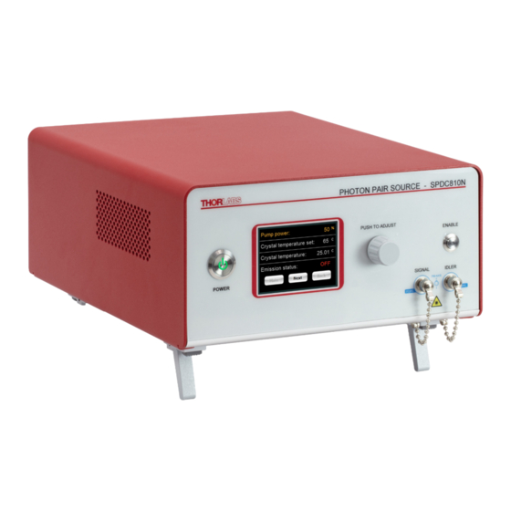
Narrowband Photon Pair Source Chapter 4: Operation Chapter 4 Operation Pump Current and Crystal Temperature Adjustment Display Knob Indicates pump current Push to adjust level (0 – 100%), crystal temperature status, and emission status Idler Output Port FC/PC Bulkhead Push‐Button Power Switch Signal Output Port FC/PC Bulkhead USB Port For remote control of pump AC Power Cord laser and crystal temperature. Connector Cooling Fan‐Do Not Block AC Power On/Off Moves air from vent holes Switch on the bottom and sides. Periodically remove dust buildup from vents for best operation. Fuse Tray Remote Interlock Input (BNC) ... - Page 10 Narrowband Photon Pair Source Chapter 4: Operation 3. Check the emission status of the device on the bottom of the screen. It should show “Off” prior to enabling the pump source. 4. Make sure the interlock input on the back panel is short‐circuited. (See Section 6 for detailed instructions.) 5. Press and release the ENABLE switch to activate the SPDC810N. There will be a 3 second delay before the pump laser powers up. During this time, the ENABLE indicator will light up and blink. 6. Adjust the pump current set‐point starting from 0% to the desired value by pressing the adjustment knob once. The “%” sign blinks in the adjustment mode, and it times out after 5 seconds. The knob must be pressed again after the time‐out in order to make additional adjustments to the pump current set‐point. The unit is now producing photon pairs and is ready to use. Adjusting the Photon Pair Rate and Wavelength Degeneracy Photon Pair Rate ‐ The photon pair rate can be controlled by varying the pump current set‐point. The pair rate specifications represent the performance at max operating set‐point (100%) and decreases as current is lowered. Wavelength Degeneracy ‐ Adjusting the temperature of the crystal will slightly change the output wavelengths of the signal and idler. This may be needed for applications requiring a more precise degree of wavelength degeneracy. Turning the SPDC810N Off Disabling the photon emission ‐ The pump laser, and therefore photon pair output can be turned off by ...
-
Page 11: Chapter 5 Remote Operation From Command-Line Interface
Narrowband Photon Pair Source Chapter 5: Remote Operation from Command‐Line Interface Chapter 5 Remote Operation from Command‐Line Interface The Command Line Interface (CLI) provides the user with a method of controlling the SPDC810N remotely over the USB interface that is emulating a serial port. A standard terminal program (such as Tera Term) can be used to send commands to the SPDC810N and receive responses. The virtual COM port settings should be set up as: Baud Rate: 115200 Data Bits: 8 bits Parity: None Stop Bits: 1 bit Flow Control: None The list below shows the list of available commands along with a brief description and syntax. Each command should be sent with a carriage return, or a line feed, or both at the end of the string. To signify variables, (variable name, format, range) will be used. {Units} will be called out for reference to the reader but should not be included in typed commands. Command/Query Description Idn? Get identification information le Enable pump diode ld Disable pump diode ldstat Get status of pump diode, ON vs OFF (Pump Power, XXX, 0 to 100) Set pump diode operating current as a percent of the sloc ... -
Page 12: Chapter 6 Making Safety Interlock Connections
Narrowband Photon Pair Source Chapter 6: Making Safety Interlock Connections Chapter 6 Making Safety Interlock Connections The SPDC810N is equipped with a remote interlock connector located on the rear panel. In order to enable the pump laser, a short circuit must be applied across the terminals of the Remote Interlock connector. This connection is made available to allow the user to connect a remotely actuated switch to the connector (i.e. an open door indicator). The switch that is connected to this interlock must be normally open (N.O.), meaning that it has to be closed in order for the unit to be enabled. If the switch is changed to an open state, the pump laser will automatically shut down. If the switch returns to a closed condition, the pump laser will not re‐enable until the ENABLE switch is pressed. All units shipped from Thorlabs are configured with a shorting BNC device installed in the interlock connector. If you are not going to use this feature then you can leave the shorting device installed and the unit will operate normally, as described throughout this manual. If you wish to make use of the interlock feature, you will need to acquire the appropriate mating connector (BNC male) and wire it to your remote interlock switch. Page 10 TTN271994‐D02 ... -
Page 13: Chapter 7 Troubleshooting
Narrowband Photon Pair Source Chapter 7: Troubleshooting Chapter 7 Troubleshooting The following table describes some typical problems that may be encountered while using the SPDC810N and possible solutions to these problems. Problem Possible Cause Solution No AC power input Make sure the AC line cord is fully inserted into the AC Input receptacle and plugged into an outlet providing 100 Unit does not turn to 240 VAC. Also ensure that the AC power switch on the on when switching back panel has been turned on. the power switch to Fuses may be open Refer to Section 3 for information on replacing open fuses. the ON position. If the problem persists, please return the unit to Thorlabs for evaluation. Unit powers on but Open Interlock Check to make sure the interlock connector is installed on does not enable the rear panel. See Section 6 for details. pressing the ENABLE button. Low pump power Check to make sure the pump laser is enabled and set to a sufficiently high percentage. Incorrect patch cable Check that the correct type of fiber patch cable for an configuration 810nm wavelength and FC/PC connector type is being used. If using the included patch cables, ensure the AR coated ends are not being mated to the bulkhead on the Unit is enabled but unit, or to another fiber. ... -
Page 14: Chapter 8 General Maintenance
Narrowband Photon Pair Source Chapter 8: General Maintenance Chapter 8 General Maintenance Aside from the AC input fuse, there are no user serviceable parts in this product. If you suspect something has failed in the unit, please contact Thorlabs for advice on returning the unit for evaluation. Always clean fiber optic connectors that will be inserted into the system and install the dust cap whenever the source is not being used. Allowing dust and dirt onto the fiber end faces will degrade coupling efficiency and possibly damage the fiber patch cables, both inside and outside. Cleaning The housing can be cleaned using a soft, slightly damp cloth. Avoid using any solvents on or near the unit. Keep the vent holes on the sides, rear and bottom of the enclosure free of dust buildup. Restricted airflow will cause the temperature controls to operate inefficiently and, in extreme cases, loss of temperature control. Connector Cleaning Always inspect and clean the ferrule end of your fiber patch cables and clean the output FC bulkheads prior to inserting the fiber patch cables into the FC bulkheads. Thorlabs offers the FCC‐7020 Fiber Cleaning Cloth Spool, which can be used for cleaning the ferrule ends of the patch cables. Please note, if cleaning is needed on the AR coated end of the included patch cables, use a solvent such as isopropanol (IPA) on a small piece of the cloth. Using a dry cloth on an AR coated end may permanently damage the fiber end face. Furthermore, the AR coated end should never be mated to another fiber and is meant for free space launching only. Additionally, each unit is shipped with a FBC250 Bulkhead and Connector Cleaner for cleaning the output ... -
Page 15: Chapter 9 Specifications
Narrowband Photon Pair Source Chapter 9: Specifications Chapter 9 Specifications Item # SPDC810N Optical Specifications Operating Wavelength 810 ± 1 nm η (Detector Excluded) >0.30 Max Pairs/Second >100 kHz Photon Bandwidth <0.25 nm Wavelength Stability ±0.1 nm Wavelength Tuning Range >8 nm Temperature Control Yes ( τ = 0) <0.1 Extinction Ratio >17 dB Lifetime >2500 Hours of Pump Emission Pump Laser Power Up to 40 mW User Serviceable No Electrical Specifications Input Voltage ... - Page 16 Narrowband Photon Pair Source Chapter 9: Specifications Second‐Order Correlation Measurement at Zero Time Delay Dimensions do not include ports or buttons used to control the unit. Please refer to the mechanical drawings for more detail. More information can be found in P. Granger, G. Roger, and A.Aspect, “Experimental Evidence for a Photon Anticorrection Effect on a Beam Splitter: A New Light on Single‐Photon Interference,” Europhysics Letters, vol. 1, no. 4, pp. 173, 1985. Page 14 TTN271994‐D02 ...
-
Page 17: Chapter 10 Mechanical Drawings
Narrowband Photon Pair Source Chapter 10: Mechanical Drawings Chapter 10 Mechanical Drawings Figure 3 SPDC810N Mechanical Drawing Rev. A, March 14, 2023 Page 15 ... -
Page 18: Chapter 11 Certifications And Compliance
Narrowband Photon Pair Source Chapter 11: Certifications and Compliance Chapter 11 Certifications and Compliance Page 16 TTN271994‐D02 ... -
Page 19: Chapter 12 Warranty And Rma Information
Narrowband Photon Pair Source Chapter 12: Warranty and RMA Information Chapter 12 Warranty and RMA Information Thorlabs verifies our compliance with the WEEE (Waste Electrical and Electronic Equipment) directive of the European Community and the corresponding national laws. Accordingly, all end users in the EC may return “end of life” Annex I category electrical and electronic equipment sold after August 13, 2005 to Thorlabs, without incurring disposal charges. Eligible units are marked with the crossed out “wheelie bin” logo (see right), were sold to and are currently owned by a company or institute within the EC and are not dissembled or contaminated. Contact Thorlabs for Annex I more information. Waste treatment is your own responsibility. “End of life” units must be returned to Thorlabs or handed to a company specializing in waste recovery. Do not dispose of the unit in a litter bin or at a public waste disposal site. It is the user’s responsibility to delete all private data stored on the device ... -
Page 20: Chapter 13 Thorlabs Worldwide Contacts
Narrowband Photon Pair Source Chapter 13: Thorlabs Worldwide Contacts Chapter 13 Thorlabs Worldwide Contacts For technical support or sales inquiries, please visit us at for our most up‐to‐date www.thorlabs.com/contact contact information. USA, Canada, and South America UK and Ireland Thorlabs, Inc. Thorlabs Ltd. sales@thorlabs.com sales.uk@thorlabs.com techsupport@thorlabs.com techsupport.uk@thorlabs.com Europe Scandinavia Thorlabs GmbH Thorlabs Sweden AB europe@thorlabs.com scandinavia@thorlabs.com France Brazil Thorlabs SAS Thorlabs Vendas de Fotônicos Ltda. sales.fr@thorlabs.com ... - Page 22 www.thorlabs.com ...
Need help?
Do you have a question about the SPDC810N and is the answer not in the manual?
Questions and answers