
Related Manuals for Rohde & Schwarz R&S FSVA


Summary of Contents for Rohde & Schwarz R&S FSVA
- Page 1 ® R&S FSVA/FSV Signal and Spectrum Analyzer Quick Start Guide (=ENÐ2) 1321.3066.02 ─ 05...
- Page 2 This manual describes the following R&S FSVA/FSV models with firmware ver- sion 3.20 and higher: ● R&S ® FSVA4 (1321.3008K05) ● R&S ® FSVA7 (1321.3008K08) ● R&S ® FSVA13 (1321.3008K14) ● R&S ® FSVA30 (1321.3008K31) ● R&S ® FSVA40 (1321.3008K41) ●...
-
Page 3: Basic Safety Instructions
Basic Safety Instructions All plants and locations of the Rohde & Schwarz group of companies make every effort to keep the safety standards of our products up to date and to offer our customers the highest possible degree of safety. Our products and the auxiliary equipment they require are designed, built and tested in accordance with the safety standards that apply in each case. - Page 4 Basic Safety Instructions Observing the safety instructions will help prevent personal injury or damage of any kind caused by dangerous situations. Therefore, carefully read through and adhere to the following safety instructions before and when using the product. It is also absolutely essential to observe the additional safety instructions on personal safety, for example, that appear in relevant parts of the product documentation.
- Page 5 Basic Safety Instructions Symbol Meaning Symbol Meaning Be careful when handling EU labeling for separate collection electrostatic sensitive devices of electrical and electronic devices For additional information, see section "Waste disposal/Environmental protection", item 2. Warning! Laser radiation For additional information, see section "Operation", item 7.
- Page 6 Basic Safety Instructions Operating states and operating positions The product may be operated only under the operating conditions and in the positions specified by the manufacturer, without the product's ventilation being obstructed. If the manufacturer's specifications are not observed, this can result in electric shock, fire and/or serious personal injury or death.
- Page 7 Basic Safety Instructions 3. Intentionally breaking the protective conductor either in the feed line or in the product itself is not permitted. Doing so can result in the danger of an electric shock from the product. If extension cords or connector strips are implemented, they must be checked on a regular basis to ensure that they are safe to use.
- Page 8 Basic Safety Instructions 12. If a product is to be permanently installed, the connection between the protective conductor terminal on site and the product's protective conductor must be made first before any other connection is made. The product may be installed and connected only by a licensed electrician.
- Page 9 Basic Safety Instructions 3. As with all industrially manufactured goods, the use of substances that induce an allergic reaction (allergens) such as nickel cannot be generally excluded. If you develop an allergic reaction (such as a skin rash, frequent sneezing, red eyes or respiratory difficulties) when using a Rohde &...
- Page 10 Basic Safety Instructions Class B equipment: Equipment suitable for use in residential environments and environments that are directly connected to a low-voltage supply network that supplies residential buildings Repair and service 1. The product may be opened only by authorized, specially trained personnel. Before any work is performed on the product or before the product is opened, it must be disconnected from the AC supply network.
- Page 11 Basic Safety Instructions 6. Improperly replacing or charging cells or batteries that contain alkaline electrolytes (e.g. lithium cells) can cause explosions. Replace cells or batteries only with the matching Rohde & Schwarz type (see parts list) in order to ensure the safety of the product. 7.
- Page 12 Instrucciones de seguridad elementales 3. If products or their components are mechanically and/or thermally processed in a manner that goes beyond their intended use, hazardous substances (heavy-metal dust such as lead, beryllium, nickel) may be released. For this reason, the product may only be disassembled by specially trained personnel. Improper disassembly may be hazardous to your health.
- Page 13 Instrucciones de seguridad elementales Además queda en la responsabilidad del usuario utilizar el producto en la forma debida. Este producto está destinado exclusivamente al uso en la industria y el laboratorio o, si ha sido expresamente autorizado, para aplicaciones de campo y de ninguna manera deberá...
- Page 14 Instrucciones de seguridad elementales Señalización de seguridad de los productos Las siguientes señales de seguridad se utilizan en los productos para advertir sobre riesgos y peligros. Símbolo Significado Símbolo Significado Aviso: punto de peligro general Tensión de alimentación de PUESTA EN MARCHA / PARADA Observar la documentación del producto Atención en el manejo de...
- Page 15 Instrucciones de seguridad elementales Palabras de señal y su significado En la documentación del producto se utilizan las siguientes palabras de señal con el fin de advertir contra riesgos y peligros. Indica una situación de peligro que, si no se evita, causa lesiones graves o incluso la muerte.
- Page 16 Instrucciones de seguridad elementales Estados operativos y posiciones de funcionamiento El producto solamente debe ser utilizado según lo indicado por el fabricante respecto a los estados operativos y posiciones de funcionamiento sin que se obstruya la ventilación. Si no se siguen las indicaciones del fabricante, pueden producirse choques eléctricos, incendios y/o lesiones graves con posible consecuencia de muerte.
- Page 17 Instrucciones de seguridad elementales 2. Los productos de la clase de protección I con alimentación móvil y enchufe individual solamente podrán enchufarse a tomas de corriente con contacto de seguridad y con conductor de protección conectado. 3. Queda prohibida la interrupción intencionada del conductor de protección, tanto en la toma de corriente como en el mismo producto.
- Page 18 Instrucciones de seguridad elementales 10. Para la conexión con dispositivos informáticos como un PC o un ordenador industrial, debe comprobarse que éstos cumplan los estándares IEC60950- 1/EN60950-1 o IEC61010-1/EN 61010-1 válidos en cada caso. 11. A menos que esté permitido expresamente, no retire nunca la tapa ni componentes de la carcasa mientras el producto esté...
- Page 19 Instrucciones de seguridad elementales Funcionamiento 1. El uso del producto requiere instrucciones especiales y una alta concentración durante el manejo. Debe asegurarse que las personas que manejen el producto estén a la altura de los requerimientos necesarios en cuanto a aptitudes físicas, psíquicas y emocionales, ya que de otra manera no se pueden excluir lesiones o daños de objetos.
- Page 20 Instrucciones de seguridad elementales 7. Los productos con láser están provistos de indicaciones de advertencia normalizadas en función de la clase de láser del que se trate. Los rayos láser pueden provocar daños de tipo biológico a causa de las propiedades de su radiación y debido a su concentración extrema de potencia electromagnética.
- Page 21 Instrucciones de seguridad elementales Baterías y acumuladores o celdas Si no se siguen (o se siguen de modo insuficiente) las indicaciones en cuanto a las baterías y acumuladores o celdas, pueden producirse explosiones, incendios y/o lesiones graves con posible consecuencia de muerte. El manejo de baterías y acumuladores con electrolitos alcalinos (p.
- Page 22 Instrucciones de seguridad elementales 2. Las asas instaladas en los productos sirven solamente de ayuda para el transporte del producto por personas. Por eso no está permitido utilizar las asas para la sujeción en o sobre medios de transporte como p. ej. grúas, carretillas elevadoras de horquilla, carros etc.
- Page 23 Instrucciones de seguridad elementales 4. En caso de que durante el trato del producto se formen sustancias peligrosas o combustibles que deban tratarse como residuos especiales (p. ej. refrigerantes o aceites de motor con intervalos de cambio definidos), deben tenerse en cuenta las indicaciones de seguridad del fabricante de dichas sustancias y las normas regionales de eliminación de residuos.
- Page 24 Customer Support Technical support – where and when you need it For quick, expert help with any Rohde & Schwarz equipment, contact one of our Customer Support Centers. A team of highly qualified engineers provides telephone support and will work with you to find a solution to your query on any aspect of the operation, programming or applications of Rohde &...
-
Page 26: Table Of Contents
® Contents R&S FSVA/FSV Contents 1 Preface..................5 1.1 Documentation Overview..............5 1.2 Conventions Used in the Documentation...........7 1.3 How to Use the Help System............... 8 1.4 New Features for R&S FSP Users............. 10 1.5 Notes for Users of R&S FSV 1307.9002Kxx Models......12 2 Front and Rear Panel View.......... - Page 27 ® Contents R&S FSVA/FSV 5.2 Means of User Interaction..............86 5.3 Setting Parameters................96 5.4 Changing the Display............... 102 6 Basic Measurement Examples......... 112 6.1 Measuring a Sinusoidal Signal............112 6.2 Measuring Harmonics of Sinusoidal Signals......... 117 6.3 Measuring Signal Spectra with Multiple Signals......121 6.4 Measurements in Zero Span............
-
Page 28: Preface
® Preface R&S FSVA/FSV Documentation Overview Preface Documentation Overview This section provides an overview of the R&S FSVA/FSV user documentation. You find it on the product page at: www.rohde-schwarz.com/manual/FSV Quick start guide Introduces the R&S FSVA/FSV and describes how to set up and start working with the product. - Page 29 ® Preface R&S FSVA/FSV Documentation Overview Service manual Describes the performance test for checking the rated specifications, module replacement and repair, firmware update, troubleshooting and fault elimination, and contains mechanical drawings and spare part lists. The service manual is available for registered users on the global Rohde &...
-
Page 30: Conventions Used In The Documentation
® Preface R&S FSVA/FSV Conventions Used in the Documentation Conventions Used in the Documentation 1.2.1 Typographical Conventions The following text markers are used throughout this documentation: Convention Description "Graphical user interface All names of graphical user interface elements on the screen, elements"... -
Page 31: How To Use The Help System
® Preface R&S FSVA/FSV How to Use the Help System The screenshots usually show a fully equipped product, that is: with all options installed. Thus, some functions shown in the screenshots may not be available in your particular product configuration. How to Use the Help System Calling context-sensitive and general help ►... - Page 32 ® Preface R&S FSVA/FSV How to Use the Help System Navigating in the table of contents ● To move through the displayed contents entries, use the UP ARROW and DOWN ARROW keys. Entries that contain further entries are marked with a plus sign.
-
Page 33: New Features For R&S Fsp Users
® Preface R&S FSVA/FSV New Features for R&S FSP Users New Features for R&S FSP Users The R&S FSVA/FSV introduces new features in R&S Signal and Spectrum Ana- lyzers. If you have used an R&S FSP before, you can find some useful informa- tion in the list below: ●... - Page 34 ® Preface R&S FSVA/FSV New Features for R&S FSP Users ● The new AUTO SET key allows for automatic level and frequency adjustment routines. Although the routine is optimized for sinusoidal signals, the minimum measurement time can also be set for bursted signals, for example. ●...
-
Page 35: Notes For Users Of R&S Fsv 1307.9002Kxx Models
® Preface R&S FSVA/FSV Notes for Users of R&S FSV 1307.9002Kxx Models ● There is a link on the Windows Desktop and in the "Start" menu to access the R&S user data. The link points to the standard directory of hardcopies and save/recall files, so if the files are to be copied on a memory stick they can be found easily. - Page 36 ® Preface R&S FSVA/FSV Notes for Users of R&S FSV 1307.9002Kxx Models ● The bandwidth extension option R&S FSV-B160 (1311.2015.xx) is not availa- ble for the R&S FSV 1307.9002Kxx models. The maximum usable I/Q analy- sis bandwidth for these models is 28 MHz, or with option R&S FSV-B70, 40 MHz.
-
Page 37: Front And Rear Panel View
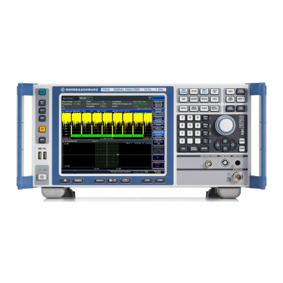
® Front and Rear Panel View R&S FSVA/FSV Front Panel View Front and Rear Panel View Front Panel View This chapter describes the front panel, including all function keys and connectors. Figure 2-1 shows the front panel view of the R&S FSVA. (The R&S FSV is very similar.) The individual elements are described in more detail in the subsequent sections. - Page 38 ® Front and Rear Panel View R&S FSVA/FSV Front Panel View Description Auxiliary functions to display Win- Chapter 2.1.1, "Function Keys on the Front dows Start menu or on-screen key- Panel", on page 16 board Display options for screen Chapter 5.4, "Changing the Display", on page 102 Navigation options for screen menu...
- Page 39 ® Front and Rear Panel View R&S FSVA/FSV Front Panel View 2.1.1 Function Keys on the Front Panel A detailed description of the corresponding menus and the other function keys is provided in chapter 6 "Instrument Functions" of the Operating Manual. Table 2-1: Front panel function keys Function key Assigned functions...
- Page 40 ® Front and Rear Panel View R&S FSVA/FSV Front Panel View Function key Assigned functions Navigation functions USER Allows you to define and use softkeys to load user-specific set- tings files. HOME Jumps to the highest softkey menu level of the current firmware option.
- Page 41 ® Front and Rear Panel View R&S FSVA/FSV Front Panel View Function key Assigned functions MKR FUNC Provides additional analysis functions of the measurement mark- ers: ● Frequency counter (Sig Count) ● Fixed reference point for relative measurement markers (Ref Fixed) ●...
- Page 42 ® Front and Rear Panel View R&S FSVA/FSV Front Panel View 2.1.2 Touchscreen Display All measurement results are displayed in the screen on the front panel. Addition- ally, the screen display provides status and setting information and allows you to switch between various measurement tasks.
- Page 43 ® Front and Rear Panel View R&S FSVA/FSV Front Panel View Figure 2-2: Touchscreen elements 1 = Toolbar with standard application functions, e.g. print, save/open file etc. 2 = Tabs for individual measurement tasks 3 = Channel information bar for current measurement settings 4 = Diagram header with diagram-specific (trace) information 5 = Measurement results area 6 = Diagram footer with diagram-specific information, depending on measurement mode...
- Page 44 ® Front and Rear Panel View R&S FSVA/FSV Front Panel View Most connectors on the front panel (except for USB) are located at the bottom right-hand side. 2.1.3.1 The front panel provides two female USB connectors to connect devices like a keyboard or mouse.
- Page 45 ® Front and Rear Panel View R&S FSVA/FSV Front Panel View current of 140 mA is available. This connector is suitable as power supply for high-impedance probes from Agilent. 2.1.3.5 POWER SENSOR The LEMOSA female connector is used to connect power sensors of the R&S NRP family (requires option R&S FSVA/FSV-K9).
- Page 46 ® Front and Rear Panel View R&S FSVA/FSV Front Panel View The output of the tracking generator is to be connected to the DUT via a cable equipped with a male N connector. The female connector is available only with the tracking generator option (R&S FSV-B9).
- Page 47 ® Front and Rear Panel View R&S FSVA/FSV Front Panel View Three-port mixer 1. Connect the LO OUT / IF IN output of the R&S FSVA/FSV to the LO port of the external mixer. 2. Connect the IF IN input of the R&S FSVA/FSV to the IF port of the external mixer.
-
Page 48: Rear Panel View
® Front and Rear Panel View R&S FSVA/FSV Rear Panel View Two-port mixer 1. 1. Connect the LO OUT / IF IN output of the R&S FSVA/FSV to the LO/IF port of the external mixer. The nominal LO level is 15.5 dBm. Because of the diplexer contained in the R&S FSVA/FSV, the IF signal can be tapped from the line which is used to feed the LO signal to the mixer. - Page 49 ® Front and Rear Panel View R&S FSVA/FSV Rear Panel View Figure 2-3: Rear panel view = LAN = TRIGGER OUTPUT = IF/VIDEO = USB = AUX PORT 6+7 = External generator control (option B10) = EXT TRIGGER / GATE IN 9+10 = DIGITAL BASEBAND INPUT/OUTPUT connectors (option B17) = MONITOR (VGA) = REF IN...
- Page 50 ® Front and Rear Panel View R&S FSVA/FSV Rear Panel View Position O: The entire instrument is disconnected from the AC power supply. For details refer to Chapter 3.1.8, "Switching the Instrument On and Off", on page 42. Warm-up time for OCXO When the instrument is switched on, the OCXO requires an extended warm-up time (see data sheet).
- Page 51 ® Front and Rear Panel View R&S FSVA/FSV Rear Panel View 2.2.1.6 REF OUT This connector can be used to provide an external reference signal (e.g. the OCXO or ultra high precision reference signal) to other devices that are connec- ted to this instrument.
- Page 52 ® Front and Rear Panel View R&S FSVA/FSV Rear Panel View EMI impact on measurement results Electromagnetic interference (EMI) can affect the measurement results. To avoid any impact, make sure that the following conditions are met: ● Use suitable double-shielded cables. ●...
- Page 53 ® Front and Rear Panel View R&S FSVA/FSV Rear Panel View 2.2.2 Optional Rear Panel Connectors 2.2.2.1 OCXO option (R&S FSV-B4) This option generates a very precise 10 MHz reference signal with an output level of ≥ 0 dBm. If installed, and if no external signal or ultra high precision reference is used (see "Ultra High Precision Reference Option (R&S FSV-B14)"...
- Page 54 ® Front and Rear Panel View R&S FSVA/FSV Rear Panel View 2.2.2.3 Digital Baseband Interface (R&S FSV-B17) The R&S FSVA/FSV Digital Baseband Interface option (R&S FSV-B17) provides an online digital I/Q data interface on the rear panel of the instrument for input and output.
-
Page 55: Preparing For Use
® Preparing for Use R&S FSVA/FSV Putting into Operation Preparing for Use Putting into Operation This section describes the basic steps to be taken when setting up the R&S FSVA/FSV for the first time. Risk of injury and instrument damage The instrument must be used in an appropriate manner to prevent electric shock, fire, personal injury, or damage. - Page 56 ® Preparing for Use R&S FSVA/FSV Putting into Operation Risk of instrument damage during operation An unsuitable operating site or test setup can damage the instrument and connected devices. Ensure the following operating conditions before you switch on the instrument: ●...
- Page 57 ® Preparing for Use R&S FSVA/FSV Putting into Operation 3.1.1 Unpacking and Checking the Instrument To remove the instrument from its packaging and check the equipment for com- pleteness, proceed as follows: 1. Pull off the polyethylene protection pads from the instrument's rear feet. 2.
- Page 58 ® Preparing for Use R&S FSVA/FSV Putting into Operation Bench Top Operation If the R&S FSVA/FSV is operated on a bench top, the surface should be flat. The instrument can be used in horizontal position, standing on its feet, or with the sup- port feet on the bottom extended.
- Page 59 ® Preparing for Use R&S FSVA/FSV Putting into Operation Risk of injury and instrument damage if stacking instruments A stack of instruments may tilt over and cause injury. Furthermore, the instruments at the bottom of the stack may be damaged due to the load imposed by the instruments on top.
- Page 60 ® Preparing for Use R&S FSVA/FSV Putting into Operation 3.1.4 Connecting the AC Power The R&S FSVA/FSV is equipped with an AC power supply connector. The R&S FSVA/FSV can be used with different AC power voltages and adapts itself automatically to it. Refer to the datasheet for the requirements of voltage and fre- quency.
- Page 61 ® Preparing for Use R&S FSVA/FSV Putting into Operation 3.1.6 Using an Optional DC Power Supply When only DC power is available, for example from a battery or in a vehicle, an optional DC power supply adapter (R&S FSV-B30) can be connected to the R&S FSVA/FSV to operate the instrument with a DC voltage of 10 V to 28 V.
- Page 62 ® Preparing for Use R&S FSVA/FSV Putting into Operation 3. Switch off the DC power supply. 3.1.7 Using an Optional Battery Pack and Charger (Options R&S FSV-B32/-B34) A lithum-ion battery pack with four rechargeable batteries is available for all R&S FSVA/FSV instruments (R&S FSV-B32). This battery pack also requires the DC power supply adapter (option R&S FSV-B30, see Chapter 3.1.6, "Using an Optional DC Power...
- Page 63 ® Preparing for Use R&S FSVA/FSV Putting into Operation 3.1.7.1 Charging the Battery Pack The battery pack is not charged in the factory. The rechargeable batteries must be charged before they are used for the first time. The R&S FSVA/FSV‑B34 charger is a standalone charging device which can be used to charge all four rechargeable batteries of the R&S FSVA/FSV‑B32 battery pack simultaneously.
- Page 64 ® Preparing for Use R&S FSVA/FSV Putting into Operation ‑ B34 charger Figure 3-2: R&S FSVA/FSV LEDs indicate the operating state of each charging slot: ● Charging Green LED flashes ● Charging completed Green LED remains lit ● Fault Red LED lights up 5.
- Page 65 ® Preparing for Use R&S FSVA/FSV Putting into Operation 3.1.8 Switching the Instrument On and Off Switching the instrument on If an optional DC power supply (R&S FSV-B30) or an optional battery pack (R&S FSV-B32) is used, you must switch on these devices first; see Chap- ter 3.1.6, "Using an Optional DC Power Supply",...
- Page 66 ® Preparing for Use R&S FSVA/FSV Putting into Operation 3.1.9 Performing a Self Alignment and a Self Test Operating temperature Before performing this functional test, make sure that the instrument has reached its operating temperature (for details, refer to the data sheet). Performing a self alignment 1.
-
Page 67: Connecting Usb Devices
® Preparing for Use R&S FSVA/FSV Connecting USB Devices 3.1.10 Checking the Supplied Options The instrument may be equipped with both hardware and firmware options. In order to check whether the installed options correspond to the options indicated on the delivery note, proceed as follows. 1. - Page 68 ® Preparing for Use R&S FSVA/FSV Connecting USB Devices When a USB device is then disconnected from the R&S FSVA/FSV, Windows immediately detects the change in hardware configuration and deactivates the corresponding driver. All USB devices can be connected to or disconnected from the instrument during operation.
-
Page 69: Connecting An External Monitor
® Preparing for Use R&S FSVA/FSV R&S FSVA/FSV Setup ment is integrated in a network, you can also install driver data stored in a net- work directory. Select "Start > Control Panel > Devices and Printers > Device Manager > Update Device drivers"... - Page 70 ® Preparing for Use R&S FSVA/FSV R&S FSVA/FSV Setup ● Aligning the Touchscreen................49 ● Setting the Screen Colors................50 ● Setting the Display Power Save Function............53 ● Selecting and Configuring Printers..............54 3.4.1 Changing the Language of the Instrument Interface You can change the language of the R&S FSVA/FSV graphical user interface (softkeys, dialog boxes, input settings etc.) to the any other installed language, if available.
-
Page 71: Setting The Date And Time
® Preparing for Use R&S FSVA/FSV R&S FSVA/FSV Setup 1. Press the SETUP key. 2. Press the "Reference Int/Ext" softkey until it is in the desired state. External reference signal It is important that the external reference signal is deactivated when switch- ing from external to internal reference to avoid interactions with the internal reference signal. - Page 72 ® Preparing for Use R&S FSVA/FSV R&S FSVA/FSV Setup Changing the time You can change hours, minutes and seconds independently of each other. 1. Select the hour, minute or seconds area of the "Time" field. 2. Enter the required setting via the keyboard or rotary knob. 3.
- Page 73 ® Preparing for Use R&S FSVA/FSV R&S FSVA/FSV Setup 4. Using a finger or any other pointing device, press the 4 markers on the screen. The touchscreen is aligned according to the executed pointing operations. 3.4.5 Setting the Screen Colors To change the colors of the displayed objects, two default color settings are provi- ded.
- Page 74 ® Preparing for Use R&S FSVA/FSV R&S FSVA/FSV Setup viewed from above or below. In the instrument's default setting, "Default Col- ors 1" is active. Remote commands: DISP:CMAP:DEF1 DISP:CMAP:DEF2 3.4.5.3 Using the Predefined Color Set 1. In the screen colors submenu (see Chapter 3.4.5.1, "Displaying the Screen Colors Submenu",...
- Page 75 ® Preparing for Use R&S FSVA/FSV R&S FSVA/FSV Setup 6. Repeat the steps for all objects that you want to change in color. 7. To change to user-defined colors, press the "Userdefined Colors" softkey. For details refer toChapter 3.4.5.4, "Defining and Using a User-Defined Color Set", on page 52.
- Page 76 ® Preparing for Use R&S FSVA/FSV R&S FSVA/FSV Setup 4. Press the arrow on the "Selected Object" list and select the object for which you want to change the color setting. 5. In the color palette, select the color you want to use for the object, or enter values for tint, saturation and brightness.
- Page 77 ® Preparing for Use R&S FSVA/FSV R&S FSVA/FSV Setup Deactivating Display Power Save ► In the "Display Setup" submenu, press the "Display Pwr Save On/Off" softkey again. "Off" is highlighted and the power save mode is switched off. 3.4.7 Selecting and Configuring Printers You can printout your measurement results using a local printer or a network printer.
- Page 78 ® Preparing for Use R&S FSVA/FSV R&S FSVA/FSV Setup ● To save the hardcopy in an image file, select one of the image types. Depending on the image type, the color depth varies (e.g. 4-bit for BMP, 24-bit for PNG and JPEG). ●...
-
Page 79: Windows Operating System
® Preparing for Use R&S FSVA/FSV Windows Operating System other colors correspond to the screen colors of the default color setting of the "Setup" menu. Remote command: HCOP:CMAP:DEF2 ● "User Defined Colors" option: You define and use your own color set for the printout. - Page 80 ® Preparing for Use R&S FSVA/FSV Windows Operating System Risk of causing instrument unusability The instrument is equipped with the Windows 7 operating system. Addi- tional software can therefore be installed on the instrument. The use and installation of additional software may impair instrument function. Thus, run only programs that Rohde &...
- Page 81 ® Preparing for Use R&S FSVA/FSV Windows Operating System For details and recommendations, see the Rohde & Schwarz White Paper 1EF96: Malware Protection Windows 10 3.5.3 Login Windows 7 requires that users identify themselves by entering a user name and password in a login window.
- Page 82 ® Preparing for Use R&S FSVA/FSV Windows Operating System Deactivating the automatic login function To deactivate the automatic login function, perform the following steps: Select the "Windows" icon in the toolbar to access the operating system of the R&S FSVA/FSV (see also Chapter 3.5.4, "Accessing the Start Menu", on page 60).
-
Page 83: Setting Up A Network (Lan) Connection
® Preparing for Use R&S FSVA/FSV Setting Up a Network (LAN) Connection Switching users when using the automatic login function Which user account is used is defined during login. However, you can also switch the user account to be used when the automatic login function is active. ►... - Page 84 ® Preparing for Use R&S FSVA/FSV Setting Up a Network (LAN) Connection assigned you the appropriate rights and adapted the Windows firewall configura- tion, you can use the interface, for example: ● To transfer data between a controlling device and the test device, e.g. to run a remote control program.
- Page 85 ® Preparing for Use R&S FSVA/FSV Setting Up a Network (LAN) Connection An IP address has to be assigned to the instrument and the computer, see Chapter 3.6.2, "Assigning the IP Address", on page 62. Note: As the R&S FSVA/FSV uses a 1 GBit LAN, a crossover cable is not necessary (due to Auto-MDI(X) functionality).
- Page 86 ® Preparing for Use R&S FSVA/FSV Setting Up a Network (LAN) Connection Risk of network errors Connection errors can affect the entire network. If your network does not support DHCP, or if you choose to disable dynamic TCP/IP configuration, you must assign valid address information before connecting the instrument to the LAN.
- Page 87 ® Preparing for Use R&S FSVA/FSV Setting Up a Network (LAN) Connection If you have entered an invalid IP address or subnet mask, the message "out of range" is displayed in the status line. The "Edit" dialog box remains open, and you can start again.
- Page 88 ® Preparing for Use R&S FSVA/FSV Setting Up a Network (LAN) Connection 5. In the "Local Area Connection Status" dialog box, select the "Properties" but- ton. The items used by the LAN connection are displayed. 6. Tap the entry named "Internet Protocol Version 4 (TCP/IPv4)" to highlight it. Quick Start Guide 1321.3066.02 ─...
- Page 89 ® Preparing for Use R&S FSVA/FSV Setting Up a Network (LAN) Connection 7. Select the "Properties" button. 8. On the "General" tab, select "Use the following DNS server addresses" and enter your own DNS addresses. For more information, refer to the Windows Help. 3.6.3 Using Computer Names In a LAN that uses a DNS server (Domain Name System server), each PC or...
-
Page 90: Lxi Configuration
® Preparing for Use R&S FSVA/FSV LXI Configuration The serial number can be found on the rear panel of the instrument. It is the third part of the device ID printed on the bar code sticker: For example, FSV4-123456 To change the computer name 1. - Page 91 ® Preparing for Use R&S FSVA/FSV LXI Configuration Restrictions Only user accounts with administrator rights can make use of the LXI func- tionality. For details see Chapter 3.5.3, "Login", on page 58. LXI Classes and LXI functionality LXI-compliant instruments are divided into three classes, A, B and C, with the functionality of the classes hierarchically based one upon the other: ●...
- Page 92 ® Preparing for Use R&S FSVA/FSV LXI Configuration Instruments of classes A and B can generate and receive software triggers via LAN messages and communicate with each other without involving the controller. The R&S FSVA/FSV complies with LXI Class C. In addition to the general class C features described above, it provides the following LXI-related functionality: ●...
- Page 93 ® Preparing for Use R&S FSVA/FSV LXI Configuration Parameter Value TCP/IP Mode DHCP + Auto IP Address Dynamic DNS Enabled ICMP Ping Enabled Password for LAN configuration LxiWebIfc The LCI for the R&S FSVA/FSV also resets the following parameters: Parameter Value Hostname <Instrument-specific name>...
- Page 94 ® Preparing for Use R&S FSVA/FSV LXI Configuration To check the instrument name select SETUP > "General setup" > "Com- puter name". To check the instrument's IP address select SETUP > "General setup" > "IP address". The "Instrument Home Page" displays the device information required by the LXI standard including the VISA resource string in read-only format.
-
Page 95: Lan Configuration
® Preparing for Use R&S FSVA/FSV LXI Configuration The navigation pane of the browser interface contains the following control ele- ments: ● "LAN Configuration" opens the LAN Configuration page. ● "LXI Glossary" opens a document with a glossary of terms related to the LXI standard. -
Page 96: Configuring The Gpib Interface
® Preparing for Use R&S FSVA/FSV Configuring the GPIB Interface ● "VXI-11" is the protocol that is used to detect the instrument in the LAN. According to the standard, LXI devices must use VXI-11 to provide a detection mechanism; other additional detection mechanisms are permitted. 3.7.3.2 Ping The instrument includes a ping server and a ping client. - Page 97 ® Preparing for Use R&S FSVA/FSV Configuring the GPIB Interface 3. Press the "GPIB" softkey. The submenu for setting the parameters of the remote control interface is dis- played. Setting the GPIB address ► In the "GPIB" menu, press the "GPIB Address" softkey. The edit dialog box for the GPIB address is displayed.
-
Page 98: Firmware Update And Installation Of Firmware Options
® Firmware Update and Installation of Firmware Options R&S FSVA/FSV Firmware Update Firmware Update and Installation of Firmware Options This chapter describes how to update the firmware and how to activate optional firmware packages. Updating the firmware or installing optional firmware requires administrator rights (see Chapter 3.5.3, "Login",... -
Page 99: Activating Firmware Options
® Firmware Update and Installation of Firmware Options R&S FSVA/FSV Activating Firmware Options 6. Press "Execute" The installation program will guide you through the installation. 7. After the firmware update, the "UNCAL" status display indicates the necessity of a self alignment. Perform a self alignment (for details refer to Chapter 3.1.9, "Performing a Self Alignment and a Self Test",... - Page 100 ® Firmware Update and Installation of Firmware Options R&S FSVA/FSV Activating Firmware Options 2. Press the "More" softkey. 3. Press the "Option Licenses" softkey. 4. Press the "Install Option" softkey. An edit dialog box is displayed. 5. Enter the option key number using the keypad. 6.
-
Page 101: Basic Operations
® Basic Operations R&S FSVA/FSV Information in the Diagram Area Basic Operations This chapter gives an overview on how to work with the R&S FSVA/FSV. It describes what kind of information is displayed in the diagram area, how to oper- ate the R&S FSVA/FSV via the front panel keys and other interaction methods, and how to use the Online Help. - Page 102 ® Basic Operations R&S FSVA/FSV Information in the Diagram Area 1 = Toolbar 2 = Channel information bar for firmware and measurement settings 3 = Toolbar toggle icon 4 = Diagram header with diagram-specific (trace) information 5 = Diagram area 6 = Diagram footer with diagram-specific information, depending on measurement mode 7 = Device status bar with error messages, progress bar and date/time display 5.1.1...
- Page 103 ® Basic Operations R&S FSVA/FSV Information in the Diagram Area Invalid settings A bullet next to the hardware setting indicates that user-defined settings are used, not automatic settings. A green bullet indicates this setting is valid and the measurement is correct. A red bullet indicates an invalid setting that does not provide useful results.
- Page 104 ® Basic Operations R&S FSVA/FSV Information in the Diagram Area Acquisition time; for ACP/CCDF measurements, IQ analyzer and option R&S FSV-K7 Demodulation bandwidth option R&S FSV-K7 only Dig Out State of digital output, option R&S FSV-B17 only 5.1.3 Measurement Settings Information In addition to the common hardware settings, the channel bar above the diagram also displays information on instrument settings that affect the measurement results even though this is not immediately apparent from the display of the mea-...
- Page 105 ® Basic Operations R&S FSVA/FSV Information in the Diagram Area Label Description 75 Ω The input impedance of the instrument is set to 75 Ω. A frequency offset ≠ 0 Hz is set. DC/AC An external DC or AC calibration signal is in use. Input source: digital I/Q (option R&S FSV-B17 only) 5.1.4 Diagram-specific and Trace Information...
- Page 106 ® Basic Operations R&S FSVA/FSV Information in the Diagram Area MIN PEAK detector SAMPLE detector AVERAGE detector RMS detector QUASIPEAK detector CISPR Average detector RMS Average detector Trace Mode Sweep mode: Clrw CLEAR/WRITE MAX HOLD MIN HOLD AVERAGE (Lin/Log/Pwr) View VIEW Marker information in Diagram Grid The x and y axis positions of the last 2 markers or delta markers that were set, as...
- Page 107 ® Basic Operations R&S FSVA/FSV Information in the Diagram Area Marker Information in Marker Table In addition to the marker information displayed within the diagram grid, a separate marker table may be displayed beneath the diagram. This table provides the fol- lowing information for all active markers: Type Marker type: N (normal), D (delta), T (temporary, internal), PWR...
- Page 108 ® Basic Operations R&S FSVA/FSV Information in the Diagram Area Hiding the status bar You can hide the status bar display, e.g. in order to enlarge the display area for the measurement results. 1. Press the DISPLAY key. 2. In the "Display Settings" dialog box, select "Status Bar State: Off". The status bar is no longer displayed.
-
Page 109: Means Of User Interaction
® Basic Operations R&S FSVA/FSV Means of User Interaction IFOVL Overload of the IF signal path after the input mixer. ● Increase the reference level. LOUNL Error in the instrument's frequency processing hardware was detected. NO REF Instrument was set to an external reference but no signal was detected on the reference input. - Page 110 ® Basic Operations R&S FSVA/FSV Means of User Interaction For most tasks, there are at least 2 alternative methods to perform them: ● Using the touchscreen ● Using other elements provided by the front panel, e.g. the keypad, rotary knob, or arrow and position keys 5.2.1 Toolbar Standard functions can be performed via the icons in the toolbar at the top of the...
- Page 111 ® Basic Operations R&S FSVA/FSV Means of User Interaction Table 5-1: Standard Application Functions in the Toolbar Icon Description Opens the "Select Mode" menu (see Chapter 5.1.1, "Channel Display", on page 79) Opens an existing measurement (settings) file Stores the current measurement file Prints the current measurement screen Saves the current measurement screen as a file (screenshot) Reverts last operation.
- Page 112 ® Basic Operations R&S FSVA/FSV Means of User Interaction Deactivating and Activating the Touchscreen Function The touchscreen function can be deactivated, e.g. when the instrument is being used for demonstration purposes and tapping the screen should not provoke an action. 1.
- Page 113 ® Basic Operations R&S FSVA/FSV Means of User Interaction You can use the TAB key on the on-screen keyboard to move the focus from one field to another in dialog boxes. 5.2.4 Keypad The keypad is used to enter alphanumeric parameters. It contains the following keys: ●...
- Page 114 ® Basic Operations R&S FSVA/FSV Means of User Interaction – If no input field is currently active, the most recently entered value is undone, i.e. the previous value is retrieved. Thus, you can toggle between two values (e.g. spans). ● ENTER key –...
- Page 115 ® Basic Operations R&S FSVA/FSV Means of User Interaction UPARROW/DNARROW keys The UPARROW or DNARROW keys do the following: ● In a numeric edit dialog box, increase or decrease the instrument parameter. ● In a list, scroll forward and backward through the list entries. ●...
- Page 116 ® Basic Operations R&S FSVA/FSV Means of User Interaction (For details on function keys in general see Chapter 2.1.1, "Function Keys on the Front Panel", on page 16.) A list of softkeys for a certain function key is also called a menu. Each softkey can either represent a specific function, or a submenu that in turn represents several softkeys.
- Page 117 ® Basic Operations R&S FSVA/FSV Means of User Interaction Some softkeys belong to a certain (firmware) option. If this option is not imple- mented in your device, the associated softkeys are not displayed. Hiding softkeys You can hide the softkey display, e.g. when using remote control, in order to enlarge the display area for the measurement results.
- Page 118 ® Basic Operations R&S FSVA/FSV Means of User Interaction If a menu entry contains an arrow to the right of it, a submenu is available for that entry. ► To close the menu, press the ESC key or click in the display outside of the menu.
-
Page 119: Setting Parameters
® Basic Operations R&S FSVA/FSV Setting Parameters Figure 5-2: Edit dialog box for parameter entry The title bar shows the name of the parameter that was selected. The entry is performed in the editing line. When the dialog box is displayed, the focus is on the editing line and it contains the currently used parameter value and its unit. - Page 120 ® Basic Operations R&S FSVA/FSV Setting Parameters 5.3.2 Entering Alphanumeric Parameters If a field requires alphanumeric input, you can use the on-screen keyboard to enter numbers and (special) characters (see also Chapter 5.2.3, "On-screen Key- board", on page 89). Figure 5-3: On-screen keyboard Alternatively, you can use the keypad.
- Page 121 ® Basic Operations R&S FSVA/FSV Setting Parameters Correcting an entry: 1. Using the arrow keys, move the cursor to the right of the entry you want to delete. 2. Press the BACKSPACE key. 3. The entry to the left of the cursor is deleted. 4.
- Page 122 ® Basic Operations R&S FSVA/FSV Setting Parameters 5.3.3 Navigating in Dialog Boxes Some of the dialog boxes are not only for parameter entry, and therefore have a more complex structure. The following figure shows an example. Changing the focus The focus on the graphical user interface is moved by pressing an element on the screen, or via the rotary knob.
- Page 123 ® Basic Operations R&S FSVA/FSV Setting Parameters Figure 5-4: Focused area Figure 5-5: Focused area in edit mode Edit mode When using the touchscreen for focus changes, all focused areas are in the edit mode automatically, if available. Otherwise, you must switch to edit mode manually.
- Page 124 ® Basic Operations R&S FSVA/FSV Setting Parameters Chapter 5.3.2, "Entering Alphanumeric Parameters", on page 97. If you edit fields, the edit mode is activated automatically when you start typing. ● To move the focus to the next interface element (e.g. field, option, list), press it on the screen, or turn the rotary knob.
-
Page 125: Changing The Display
® Basic Operations R&S FSVA/FSV Changing the Display Particularities in Windows dialog boxes In some cases, e.g. if you want to install a printer, original Windows dialog boxes are used. In these dialog boxes, the navigation behavior is different to the one you are used to from R&S FSVA/FSV applications. - Page 126 ® Basic Operations R&S FSVA/FSV Changing the Display SCPI command: DISP:WIND:SIZE 5.4.3 Soft and Mini Soft Front Panel Display When working with an external monitor or operating via remote control on a com- puter, it is useful to be able to interact with the R&S FSVA/FSV without requiring the keypad and keys located on the front panel of the instrument.
- Page 127 ® Basic Operations R&S FSVA/FSV Changing the Display Using the F6 key you can toggle the Front Panel display on and off. Remote: SYST:DISP:FPAN:STAT ON Working with the Soft Front Panel Basic operation with the soft Front Panel is identical to normal operation. To acti- vate a key, either press the key on the touchscreen, or click on it with the mouse pointer.
- Page 128 ® Basic Operations R&S FSVA/FSV Changing the Display 2. In the "Display Settings" dialog box, select "Mini Front Panel State: On". The "Mini Front Panel" window appears on the screen. It can be moved any- where on the screen where it does not interfere with your current task. Using the key combination ALT + M you can toggle the Mini Front Panel display on and off.
- Page 129 ® Basic Operations R&S FSVA/FSV Changing the Display 5.4.4 Enlarging the Display Area You can enlarge the screen display area if you are using an external monitor or the Soft and Mini Soft Frontpanel display (see Chapter 5.4.3, "Soft and Mini Soft Front Panel Display", on page 103).
- Page 130 ® Basic Operations R&S FSVA/FSV Changing the Display Zoom and the number of sweep points Note that zooming is merely a visual tool, it does not change any measure- ment settings, such as the number of sweep points! You should increase the number of sweep points before zooming, as other- wise the function has no real effect (see the "Sweep Points"...
- Page 131 ® Basic Operations R&S FSVA/FSV Changing the Display Scrolling in the zoomed display You can scroll the diagram area to display the entire diagram using the scrollbars at the right and at the bottom of the diagram. To return to selection mode in the diagram While you are in zoom mode, touching the screen changes the zoom area.
- Page 132 ® Basic Operations R&S FSVA/FSV Changing the Display DISP:ZOOM:AREA 5,30,20,100 3. Hide the overview window: DISP:ZOOM:OVER OFF 5.4.7 Adding a Title to the Diagram Header You can add an introductory title to the trace information in the diagram header. 1. Press the SETUP key. 2.
- Page 133 ® Basic Operations R&S FSVA/FSV Changing the Display 3. Press the "More" softkey. 4. Press the "Theme Selection" softkey. A list of available themes is displayed. 5. Select the desired theme from the list. The screen display changes according to the selected theme. SCPI command: DISPlay:THEMe:SELect 5.4.10 Displaying and Setting the Date and Time...
- Page 134 ® Basic Operations R&S FSVA/FSV Changing the Display To descrease the display update rate 1. Press the DISPLAY key. The "Display Settings" dialog box is opened. 2. Under "Display Update Rate", select "Slow". The display is updated less frequently, and performance for measurements should improve.
-
Page 135: Basic Measurement Examples
® Basic Measurement Examples R&S FSVA/FSV Measuring a Sinusoidal Signal Basic Measurement Examples The measurement examples provided in this chapter are intended as an introduc- tion to operating the R&S FSVA/FSV. For advanced applications, refer to chapter "Advanced measurement examples" of the operating manual on CD. There you find the following topics: ●... - Page 136 ® Basic Measurement Examples R&S FSVA/FSV Measuring a Sinusoidal Signal Test setup ● Connect the RF output of the signal generator to the RF input of R&S FSVA/ FSV. Table 6-1: Signal generator settings (e.g. R&S SMU) Frequency 128 MHz Level -30 dBm 6.1.1...
- Page 137 ® Basic Measurement Examples R&S FSVA/FSV Measuring a Sinusoidal Signal M1[1] -30.00 dBm 128.00000 MHz The field header indicates the number of the marker (Marker 1) and the trace on which the marker is located ([1] = Trace 1). Note: Performing a peak search. When a marker is initially activated, it auto- matically performs the peak search function (as shown in the example).
- Page 138 ® Basic Measurement Examples R&S FSVA/FSV Measuring a Sinusoidal Signal Low Reference Levels If the selected reference level is lower than the highest signal that occurs in the spectrum, the signal path in the R&S FSVA/FSV is overloaded. In this case, the message "IFOVL" is displayed in the error message field. In the presettings, the value of the reference level is -10 dBm.
- Page 139 ® Basic Measurement Examples R&S FSVA/FSV Measuring a Sinusoidal Signal 6.1.2 Measuring the Signal Frequency Using the Frequency Counter The built-in frequency counter allows you to measure the frequency more accu- rately than measuring it with the marker. The frequency sweep is stopped at the marker, and the R&S FSVA/FSV measures the frequency of the signal at the marker position.
-
Page 140: Measuring Harmonics Of Sinusoidal Signals
® Basic Measurement Examples R&S FSVA/FSV Measuring Harmonics of Sinusoidal Signals Figure 6-1: Measurement of the frequency with the frequency counter Prerequisites for using the internal frequency counter In order to obtain a correct result when measuring the frequency with the internal frequency counter, an RF sinusoidal signal or a spectral line must be available. - Page 141 ® Basic Measurement Examples R&S FSVA/FSV Measuring Harmonics of Sinusoidal Signals Measuring the Suppression of the First and Second Harmonic of an Input Signal 1. Set the signal analyzer to the default state by pressing the PRESET key. The R&S FSVA/FSV is in the default state. 2.
- Page 142 ® Basic Measurement Examples R&S FSVA/FSV Measuring Harmonics of Sinusoidal Signals Figure 6-2: Measuring the harmonic suppression of the internal reference generator. Delta markers D2 [1] and D3 [1] show the offset of the first and second harmonics from the fundamental. Reducing Noise The signal analyzer offers three methods to differentiate the harmonics of a signal from the noise effectively:...
- Page 143 ® Basic Measurement Examples R&S FSVA/FSV Measuring Harmonics of Sinusoidal Signals Reducing the noise by reducing the video bandwidth 1. Press the BW key. 2. Press the "Video BW Manual" softkey. 3. Reduce the video bandwidth to 1 kHz (for example), by entering 1 kHz. This smoothes the noise significantly, and the sweep time is increased to 200 ms.
-
Page 144: Measuring Signal Spectra With Multiple Signals
® Basic Measurement Examples R&S FSVA/FSV Measuring Signal Spectra with Multiple Signals 2. Press the "Trace Wizard" softkey. 3. For "Trace 1", press the button in the "Trace Mode" column and select "Aver- age" from the list. The noise component of the trace is smoothed by averaging 10 successive traces. - Page 145 ® Basic Measurement Examples R&S FSVA/FSV Measuring Signal Spectra with Multiple Signals An RF sinusoidal signal is displayed using the passband characteristic of the defined resolution filter (RBW). Its specified bandwidth is the 3 dB bandwidth of the filter. Two signals with the same amplitude can be resolved if the resolution bandwidth is smaller than or equal to the frequency spacing of the signal.
- Page 146 ® Basic Measurement Examples R&S FSVA/FSV Measuring Signal Spectra with Multiple Signals b) Press the SPAN key and enter 300 kHz. 3. Set the resolution bandwidth to 30 kHz and the video bandwidth to 1 kHz. a) Press the BW key b) Press the "Res BW Manual"...
- Page 147 ® Basic Measurement Examples R&S FSVA/FSV Measuring Signal Spectra with Multiple Signals 4. Set the resolution bandwidth to 100 kHz. To do so, in the bandwidth menu, press the "Res BW Manual" softkey and enter 100 kHz. It is no longer possible to clearly distinguish the two generator signals. Figure 6-5: Measurement of two equally-leveled RF sinusoidal signals with a resolu- tion bandwidth which is larger than their frequency spacing Note: Reducing the resolution bandwidth.
- Page 148 ® Basic Measurement Examples R&S FSVA/FSV Measuring Signal Spectra with Multiple Signals Figure 6-6: Measurement of two equally-leveled RF sinusoidal signals with a resolu- tion bandwidth (1 kHz) which is significantly smaller than their frequency spacing 6.3.2 Measuring the Modulation Depth of an AM-Modulated Carrier (Span >...
- Page 149 ® Basic Measurement Examples R&S FSVA/FSV Measuring Signal Spectra with Multiple Signals Table 6-3: Signal generator settings (e.g. R&S SMU) Frequency 128 MHz Level -30 dBm Modulation 50 % AM, 10 kHz AF 1. Set the signal analyzer to the default state by pressing the PRESET key. The R&S FSVA/FSV is set to its default state.
- Page 150 ® Basic Measurement Examples R&S FSVA/FSV Measuring Signal Spectra with Multiple Signals 6.3.3 Measuring AM-Modulated Signals The signal analyzer rectifies the RF input signal and displays it as a magnitude spectrum. The rectification also demodulates AM-modulated signals. The AF volt- age can be displayed in zero span if the modulation sidebands fall within the res- olution bandwidth.
-
Page 151: Measurements In Zero Span
® Basic Measurement Examples R&S FSVA/FSV Measurements in Zero Span c) Press the "Trg/Gate Level" softkey and enter 50%. The trigger level is displayed as a horizontal line across the entire mea- surement diagram. The R&S FSVA/FSV displays the 1 kHz AF signal as a static image in zero span. - Page 152 ® Basic Measurement Examples R&S FSVA/FSV Measurements in Zero Span Table 6-5: Signal generator settings (e.g. R&S SMU) Frequency 890 MHz Level 0 dBm Modulation GSM, one timeslot activated 1. Set the signal analyzer to the default state by pressing the PRESET key. The R&S FSVA/FSV is set to its default state.
- Page 153 ® Basic Measurement Examples R&S FSVA/FSV Measurements in Zero Span e) By turning the rotary knob clockwise, move the vertical line to the start of the burst. f) Press the "Right Limit" softkey. g) By turning the rotary knob counterclockwise, set the second vertical line to the end of the burst.
- Page 154 ® Basic Measurement Examples R&S FSVA/FSV Measurements in Zero Span Table 6-6: Signal generator settings (e.g. R&S SMU) Frequency 890 MHz Level 0 dBm Modulation GSM, one timeslot activated The measurement is based on the setting in the example above for measuring the power of the GSM during the activation phase.
- Page 155 ® Basic Measurement Examples R&S FSVA/FSV Measurements in Zero Span c) By turning the rotary knob counterclockwise, move the trigger offset until the burst edge can be seen in the center of the screen, or enter -50 µs. The R&S FSVA/FSV displays the rising edge of the GSM burst. Figure 6-9: Rising edge of the GSM burst displayed with high time resolution 4.
- Page 156 ® Basic Measurement Examples R&S FSVA/FSV Measurements in Zero Span Figure 6-10: Falling edge of the GSM burst displayed with high time resolution 6.4.2 Measuring the Signal-to-Noise Ratio of Burst Signals When TDMA transmission methods are used, the signal-to-noise ratio or the deactivation dynamic range can be measured by comparing the power values during the activation phase and the deactivation phase of the transmission burst.
- Page 157 ® Basic Measurement Examples R&S FSVA/FSV Measurements in Zero Span Table 6-7: Signal generator settings (e.g. R&S SMU) Frequency 890 MHz Level 0 dBm Modulation GSM, one time slot is switched on 1. Set the signal analyzer to the default state by pressing the PRESET key. The R&S FSVA/FSV is set to its default state.
- Page 158 ® Basic Measurement Examples R&S FSVA/FSV Measurements in Zero Span e) Using the rotary knob, move the vertical line to the start of the burst. f) Press the "Right Limit" softkey. g) Using the rotary knob, move the second vertical line to the end of the burst.
- Page 159 ® Basic Measurement Examples R&S FSVA/FSV Measurements in Zero Span b) Switch the "Trg/Gate Polarity" softkey to "Neg." The R&S FSVA/FSV initiates triggering in response to the falling edge of the burst. This shifts the burst to the left-hand half of the measurement dia- gram.
- Page 160 ® Basic Measurement Examples R&S FSVA/FSV Measurements in Zero Span frequency). The resolution bandwidth and the frequency offset must be selected in such a manner that the instantaneous frequency is located in the linear part of the filter edge. As a result, the frequency variation of the FM-modulated signal is transformed into an amplitude variation that can be displayed on screen in zero span.
- Page 161 ® Basic Measurement Examples R&S FSVA/FSV Measurements in Zero Span i) Using the rotary knob, set the reference level such that the filter edge at the center frequency intersects the -10 dB level line. The filter edge of the 300 kHz filter is displayed. This corresponds to the demodulator characteristic for FM signals with a steepness of approx.
- Page 162 ® Basic Measurement Examples R&S FSVA/FSV Measurements in Zero Span c) Press the "Trg/Gate Level" softkey and enter 50%. A static image for the FM AF signal is produced. Result: (-10 ( 5) dB; this yields a deviation of 100 kHz when the steepness of the demodulator characteristic is 5 dB/100 kHz.
-
Page 163: Storing And Loading Instrument Settings
® Basic Measurement Examples R&S FSVA/FSV Storing and Loading Instrument Settings Storing and Loading Instrument Settings The R&S FSVA/FSV can store complete instrument settings together with instru- ment configurations and measurement data in a settings file. The data is stored on the built-in hard disk or - if selected - on a USB device (e.g. - Page 164 ® Basic Measurement Examples R&S FSVA/FSV Storing and Loading Instrument Settings The name may contain letters and digits. For details on alphanumeric entries Chapter 5.3.2, "Entering Alphanumeric Parameters", on page 97. 4. To store the file in a directory different to the default directory, select the required path in the Files area.
- Page 165 ® Basic Measurement Examples R&S FSVA/FSV Storing and Loading Instrument Settings a) Press the "Select File" softkey. The focus is set on the files list. b) Using the rotary knob or arrow keys, focus the settings file to be loaded and confirm by pressing the rotary knob or the ENTER key.
-
Page 166: Brief Introduction To Remote Control
® Brief Introduction to Remote Control R&S FSVA/FSV Basic Steps in Remote Control Programming Brief Introduction to Remote Control The instrument can be remote-controlled via the network (LAN interface). For details on configuring the LAN interface see Chapter 3.6, "Setting Up a Network (LAN) Connection", on page 60. - Page 167 ® Brief Introduction to Remote Control R&S FSVA/FSV Basic Steps in Remote Control Programming 7.1.1 Linking the Remote Control Library for Visual Basic Programming notes: ● Outputting text using the print function Using the print method, this example displays the value of the variable MyVar in the "Immediate"...
- Page 168 ® Brief Introduction to Remote Control R&S FSVA/FSV Basic Steps in Remote Control Programming Since the DLL returns zero-terminated strings in responses, a string of suffi- cient length must be created before the functions InstrRead() and ilrd() are called, because Visual Basic inserts a length specification in front of the strings and this specification is not updated by the DLL.
- Page 169 ® Brief Introduction to Remote Control R&S FSVA/FSV Basic Steps in Remote Control Programming ErrorMessage = "" If (status < 0) Then 'Query the error message from VISA If (viStatusDesc(vi, status, ErrorMessage) = VI_SUCCESS) Then Err.Description = ErrorMessage End If Err.Raise (status) End If End Sub...
- Page 170 ® Brief Introduction to Remote Control R&S FSVA/FSV Basic Steps in Remote Control Programming 'timeout values are in milliseconds 'This example assumes the instrument IP address 10.0.0.10 'If the network provides a name resolution mechanism, the hostname of 'the instrument can be used instead of the numeric IP address 'the resource string for GPIB would be "GPIB::20::INSTR'' status = viOpen(defaultRM, "TCPIP::10.0.0.10::INSTR'', 0, 1000, analyzer) 'status = viOpen(defaultRM, "TCPIP::<hostname>::INSTR'', 0, 1000, analyzer)
- Page 171 ® Brief Introduction to Remote Control R&S FSVA/FSV Basic Steps in Remote Control Programming CALL InstrWrite(analyzer, "SYST:DISP:UPD OFF") 'Switch off screen display END SUB REM************************************************************************* 7.1.2.5 Configuring the Power Save Function for the Display During remote control operation, it is often unnecessary to display the measure- ment results on screen.
- Page 172 ® Brief Introduction to Remote Control R&S FSVA/FSV Basic Steps in Remote Control Programming 7.1.4 Switching to Manual Operation REM -------- Switching instrument to manual operation ---------------------- CALL viGpibControlREN(analyzer, VI_GPIB_REN_ADDRESS_GTL) 'Set instrument to Local state REM ************************************************************************ 7.1.5 Reading Out Instrument Settings The settings made above can now be read out.
- Page 173 ® Brief Introduction to Remote Control R&S FSVA/FSV Basic Steps in Remote Control Programming MKmark$ = SPACE$(30) 'Provide text variable (30 characters) CALL InstrWrite(analyzer, "CALC:MARK:X?;Y?") 'Query frequency and level CALL InstrRead(analyzer, MKmark$, 30, retCount) 'Read value REM --------- Displaying values in the Immediate window ------------------- Debug.Print "Marker frequency/level ";...
-
Page 174: Detailed Programming Examples
® Brief Introduction to Remote Control R&S FSVA/FSV Detailed Programming Examples SRQWaitTimeout = 5000 'Allow 5s for sweep completion 'Now wait for the service request CALL viWaitOnEvent(vi, VI_EVENT_SERVICE_REQ, SRQWaitTimeout, _ eventType, eventVi) CALL viClose(eventVi) 'Close the context before continuing CALL viDisableEvent(vi, VI_EVENT_SERVICE_REQ, VI_QUEUE) 'Disable subsequent events REM Resume main program here. - Page 175 ® Brief Introduction to Remote Control R&S FSVA/FSV Detailed Programming Examples 7.2.1 Default Setting of the R&S FSVA/FSV The following settings provide typical examples of how to change the default set- ting of the R&S FSVA/FSV. Note that only some of the settings are necessary depending on the application example.
- Page 176 ® Brief Introduction to Remote Control R&S FSVA/FSV Detailed Programming Examples CALL InstrWrite(analyzer,"*RST") 'Reset instrument CALL InstrWrite(analyzer,"SYST:DISP:UPD ON") 'ON: screen display on 'OFF: off (improved performance) CALL InstrWrite(analyzer,"INIT:CONT OFF") 'Single sweep mode '--------- Frequency setting ----------------------------------------------- CALL InstrWrite(analyzer,"FREQUENCY:CENTER 100MHz") 'Center frequency CALL InstrWrite(analyzer,"FREQ:SPAN 1 MHz") 'Span '--------- Level setting ---------------------------------------------------...
- Page 177 ® Brief Introduction to Remote Control R&S FSVA/FSV Detailed Programming Examples CALL InstrWrite(analyzer,"DET2:AUTO ON") 'Detector Trace2 CALL InstrWrite(analyzer,"DET3:AUTO ON") 'Detector Trace3 CALL InstrWrite(analyzer,"DET4:AUTO ON") 'Detector Trace4 CALL InstrWrite(analyzer,"DET5:AUTO ON") 'Detector Trace5 CALL InstrWrite(analyzer,"DET6:AUTO ON") 'Detector Trace6 '--------- Bandwidths and sweep time --------------------------------------- CALL InstrWrite(analyzer,"BAND:RES 100KHz") 'Resolution bandwidth (*) CALL InstrWrite(analyzer,"BAND:VID 1MHz")
- Page 178 ® Brief Introduction to Remote Control R&S FSVA/FSV Detailed Programming Examples '--------- Peak search without search range limits-------------------------- CALL InstrWrite(analyzer,"INIT:CONT OFF") 'Switch to single sweep CALL InstrWrite(analyzer,"CALC:MARK:PEXC 6DB") 'Define peak excursion CALL InstrWrite(analyzer,"CALC:MARK:STAT ON") 'Enable marker 1 CALL InstrWrite(analyzer,"CALC:MARK:TRAC 1") 'Set marker 1 to trace 1 CALL InstrWrite(analyzer,"INIT;*WAI") 'Perform sweep with sync...
- Page 179 ® Brief Introduction to Remote Control R&S FSVA/FSV Detailed Programming Examples 'frequency and level; 'both must have a value of 0 result$ = Space$(100) CALL InstrRead(analyzer, result$, 100, retCount) Debug.Print "Delta 3: ";result$ '---- Setting center frequency and reference level with markers ------------ CALL InstrWrite(analyzer,"CALC:MARK2:FUNC:CENT") 'Delta marker 2 ->...
- Page 180 ® Brief Introduction to Remote Control R&S FSVA/FSV Detailed Programming Examples END SUB REM ************************************************************************* 7.2.2.3 Working with a Fixed Reference Point The following example is based on a signal at 100 MHz with a level of -20 dBm. Thus, the harmonics of the signal are located at 200 MHz, 300 MHz, etc. For high-quality signal sources, these harmonics may be located outside the dynamic range of the R&S FSVA/FSV.
- Page 181 ® Brief Introduction to Remote Control R&S FSVA/FSV Detailed Programming Examples CALL InstrWrite(analyzer,"SWEEP:TIME:AUTO ON") 'Couple sweep time CALL InstrWrite(analyzer,"INP:ATT:AUTO ON") 'Select more sensitive level setting CALL InstrWrite(analyzer,"DISP:WIND:TRAC:Y:RLEV -50dBm") CALL InstrWrite(analyzer,"INIT;*WAI") 'Perform sweep with sync CALL InstrWrite(analyzer,"CALC:DELT:MAX;X:REL?;Y?") 'Read delta marker result$ = Space$(100) CALL InstrRead(analyzer, result$, 100, retCount) 'Read frequency and level Debug.Print "Deltamarker 1: ";...
- Page 182 ® Brief Introduction to Remote Control R&S FSVA/FSV Detailed Programming Examples CALL InstrWrite(analyzer,"CALC:MARK:PEXC 6DB") 'Define peak excursion CALL InstrWrite(analyzer,"CALC:MARK:STAT ON") 'Activate marker 1 CALL InstrWrite(analyzer,"CALC:MARK:TRAC 1") 'Set marker 1 to trace 1 CALL InstrWrite(analyzer,"CALC:MARK:MAX") 'Set marker 1 to 100 MHz CALL InstrWrite(analyzer,"CALC:DELT:FUNC:PNO ON") 'Define reference point for phase noise '--------- Measuring the phase noise --------------------------------------...
- Page 183 ® Brief Introduction to Remote Control R&S FSVA/FSV Detailed Programming Examples 2. The length specification itself is read out. 3. The trace data itself is read out. The procedure is required for programming languages that only support struc- tures with data types of the same type (arrays, such as with Visual Basic), because the data types of the header and data sections are different in binary data.
- Page 184 ® Brief Introduction to Remote Control R&S FSVA/FSV Detailed Programming Examples CALL InstrRead(analyzer,span$, 100, retCount) span = Val(span$) '--------- Reading out in binary format ------------------------------------ CALL InstrWrite(analyzer, "FORMAT REAL,32") 'Set binary format CALL InstrWrite(analyzer, "TRAC1? TRACE1") 'Read trace 1 CALL InstrRead(analyzer, result$, 2, retCount) 'Read and store length digits = Val(Mid$(result$, 2, 1)) 'spec.
- Page 185 ® Brief Introduction to Remote Control R&S FSVA/FSV Detailed Programming Examples 7.2.4.1 Storing Instrument Settings In the following example, the settings/measured data to be stored are defined ini- tially, in which case only the hardware settings are stored. However, the selection commands for the other settings are specified with the state "OFF"...
- Page 186 ® Brief Introduction to Remote Control R&S FSVA/FSV Detailed Programming Examples CALL InstrWrite(analyzer,"DISP:TRAC1:MODE WRIT") 'Set trace to Clr/Write CALL InstrWrite(analyzer,"INIT;*WAI") 'Start sweep END SUB REM ************************************************************************ 7.2.4.3 Setting the Data Record for Startup Recall In the following example, the first step is to change the R&S FSVA/FSV to the default state.
- Page 187 ® Brief Introduction to Remote Control R&S FSVA/FSV Detailed Programming Examples It is assumed that the desired setting is a signal at 100 MHz with a power of -20 dBm. It is also assumed that the sixth printer out of the available printers that are listed is the one you want.
- Page 188 ® Brief Introduction to Remote Control R&S FSVA/FSV Detailed Programming Examples 'Printer selection #6 CALL InstrWrite(analyzer,"HCOP:DEST 'SYST:COMM:PRIN'") 'Configuration: "Printout to 'printer interface" CALL InstrWrite(analyzer,"HCOP:DEV:LANG GDI") 'Printers require printer language 'GDI' '----- Selection of orientation (portrait/landscape) and colour/BW --------- CALL InstrWrite(analyzer,"HCOP:PAGE:ORI PORT") 'Portrait orientation CALL InstrWrite(analyzer,"HCOP:DEV:COL OFF") 'Black-and-white printout...
- Page 189 ® Brief Introduction to Remote Control R&S FSVA/FSV Detailed Programming Examples statusSRQ = viWaitOnEvent(vi, VI_EVENT_SERVICE_REQ, SRQWaitTimeout, _ eventType, eventVi) CALL viClose(eventVi) 'Close the context before continuing CALL viDisableEvent(vi, VI_EVENT_SERVICE_REQ, VI_QUEUE) 'Disable subsequent events IF NOT(statusSRQ = 0) THEN CALL Srq 'If SRQ not detected =>...
-
Page 190: Appendix: Lan Interface
® Appendix: LAN Interface R&S FSVA/FSV Configuring the Network Appendix: LAN Interface In this appendix, additional information on the LAN interface is given. How to con- nect the instrument to the network and configure the network protocols is descri- bed in Chapter 3.6, "Setting Up a Network (LAN) Connection", on page 60. - Page 191 ® Appendix: LAN Interface R&S FSVA/FSV Configuring the Network Connection to networks Before connecting the instrument to the network or configuring the network, consult your network administrator, particularly for large LAN installations. Errors may affect the entire network. Never connect your analyzer to a network unprotected against virus infec- tion because this may cause damage to the instrument software.
- Page 192 ® Appendix: LAN Interface R&S FSVA/FSV Configuring the Network 8.1.2 Changing the Domain or Workgroup Changing settings Before you change other settings than described here, contact your network administrator. 1. Press the "Windows" key on the external keyboard or the CTRL + ESC key combination on your keyboard to access the operating system.
- Page 193 ® Appendix: LAN Interface R&S FSVA/FSV Configuring the Network 8.1.3 Operating the Instrument Without a Network To operate the instrument without a network connection either temporarily or per- manently, no special measures are necessary. Windows automatically detects the interruption of the network connection and does not set up the connection when the instrument is switched on.
- Page 194 ® Appendix: LAN Interface R&S FSVA/FSV Configuring the Network 8.1.5 Changing the User Password After the new user has been created on the instrument, the password must be adapted to the network password. 1. Press the "Windows" key on the external keyboard or the CTRL + ESC key combination on your keyboard to access the operating system.
- Page 195 ® Appendix: LAN Interface R&S FSVA/FSV Configuring the Network 3. Enter the command C:\R_S\INSTR\USER\NO_AUTOLOGIN.REG. 4. Press the ENTER key to confirm. The automatic login function is deactivated. The next time you switch on the instrument, you are prompted to enter your user name and password before the firmware is started.
- Page 196 ® Appendix: LAN Interface R&S FSVA/FSV Configuring the Network 8.1.8 Mapping Network Drives 1. Press the SAVE/ RCL key on the front panel of the R&S FSVA/FSV. 2. Press the "File Manager" softkey. 3. Press the "More" softkey. 4. Press the "Network Drive" softkey. The "Map Network Drive"...
- Page 197 ® Appendix: LAN Interface R&S FSVA/FSV Configuring the Network 8. Enter your user name and password. 9. Confirm with "OK". The drive is displayed in the Explorer. Note: Only networks that you authorized to access are connected. Disconnecting network drives 1.
-
Page 198: Operation With Windows Remote Desktop
® Appendix: LAN Interface R&S FSVA/FSV Operation with Windows Remote Desktop 4. In the context menu, select "Share with > Specific people". 5. Select the users on your network you want to allow access to the directory to. 6. Select "Share" to confirm the settings. 7. - Page 199 ® Appendix: LAN Interface R&S FSVA/FSV Operation with Windows Remote Desktop 2. Select "Start > Control Panel > System and Security > System > Allow remote access". 3. In the "System Properties" dialog box, in the "Remote" tab, select one of the "Allow connections..."...
- Page 200 ® Appendix: LAN Interface R&S FSVA/FSV Operation with Windows Remote Desktop 8.2.2 Configuring the Controller Remote Desktop Client The Windows Remote Desktop Client is part of the operating system and can be accessed via "Start > All Programs > Accessories > Remote Desk- top Connection".
-
Page 201: Operation With A Vnc Client
® Appendix: LAN Interface R&S FSVA/FSV Operation with a VNC Client Depending on your selection (and how powerful the connection is), the options are activated or deactivated. 6. To improve the performance, you can deactivate the "Desktop background", "Show contents of window while dragging" and "Menu and window animation" options. - Page 202 ® Appendix: LAN Interface R&S FSVA/FSV Operation with a VNC Client the Windows Remote Desktop, but VNC has some advantages compared to the Remote Desktop. ● You can view the contents of the instrument display on more than one client ●...
-
Page 203: Starting And Terminating Remote Operation
® Appendix: LAN Interface R&S FSVA/FSV Starting and Terminating Remote Operation Starting and Terminating Remote Operation Setting up a connection to the R&S FSVA/FSV 1. In the "Remote Desktop Connection" dialog box (see Chapter 8.2, "Operation with Windows Remote Desktop ", on page 175), open the "General"... - Page 204 ® Appendix: LAN Interface R&S FSVA/FSV Starting and Terminating Remote Operation 8. To deactivate or activate the "Soft Front Panel", press the F6 key. After the connection is established, the R&S FSVA/FSV screen is displayed in the "Remote Desktop" application window. You can operate all keys and softkeys using the mouse.
-
Page 205: Deactivating The R&S Fsva/Fsv Via Remote Operation
® Appendix: LAN Interface R&S FSVA/FSV Deactivating the R&S FSVA/FSV via Remote Operation Restoring the connection to the R&S FSVA/FSV Follow the instructions above for setting up a connection to the R&S FSVA/FSV. If the connection is terminated and then restored, the R&S FSVA/FSV remains in the same state. -
Page 206: Index
® Index R&S FSVA/FSV Index Symbols LAN ............. 27 MONITOR (VGA) ........ 27 75 Ω (enhancement label) ....... 82 Noise source control ......21 OCXO ..........30 Power Sensor ........22 AC supply fuse ........37 Probe power ........21 Administrator rights ......... - Page 207 ® Index R&S FSVA/FSV Electrostatic discharge ......33 Instrument name Enhancement labels ........ 81 Changing ..........64 Entry Interface Canceling ..........90 LAN ........... 167 Concluding .......... 90 IP address Error messages Changing ..........62 see User Manual .........85 ESD ............33 EXREF (status display) ......
- Page 208 ® Index R&S FSVA/FSV Online help ..........5 Working with ......... 8 MAXH (trace information) ......83 Operating system ........56 Measurement data Login ........... 58 Loading ..........141 service packs ........57 Storing ..........141 Options Measurement example Activating ..........76 AF of AM-modulated signal ....
- Page 209 ® Index R&S FSVA/FSV Remote control Storing Command synchronization ....150 Instrument configuration ....140 Configuration ........175 Measurement data ......141 Deactivating the instrument ....182 SWT (hardware setting) ......80 Display power save ......148 Ending session ......... 180 Global variables ........
- Page 210 ® Index R&S FSVA/FSV VBW (hardware setting) ......80 Virus protection ........57 VNC ............178 White papers ..........6 Windows 7 ..........56 Windows 7 Access ..........60 Wordpad Accessing ........... 60 Zero span measurements ..... 128 Quick Start Guide 1321.3066.02 ─ 05...
Need help?
Do you have a question about the R&S FSVA and is the answer not in the manual?
Questions and answers