Table of Contents
Advertisement
Quick Links
Advertisement
Table of Contents
Troubleshooting

Related Manuals for Flomec RT40


Summary of Contents for Flomec RT40
- Page 1 RT40 Flow Rate Totaliser Instruction Manual...
- Page 2 General Information This manual provides the necessary information for installation and operation of your flow instrument; for detailed information on any flowmeters or accessories supplied with your instrument please consult the relevant flowmeter product manual. This instrument should only be installed and maintained by persons familiar with local regulations, particularly those for workplace Health and Safety.
-
Page 3: Table Of Contents
Table of Contents Introduction ....................4 Product Overview.....................4 Specifications ....................5 Operation ....................... 6 LCD Display ......................6 Keypad Function ....................7 Operating Functions ..................7 Mechanical Installation ................12 General Requirements ...................12 Electrical Entries ....................12 Integral Meter Mounting ................12 Wall and Pipe Mounting ................12 Panel Mounting .....................13 Electrical Installation .................. -
Page 4: Introduction
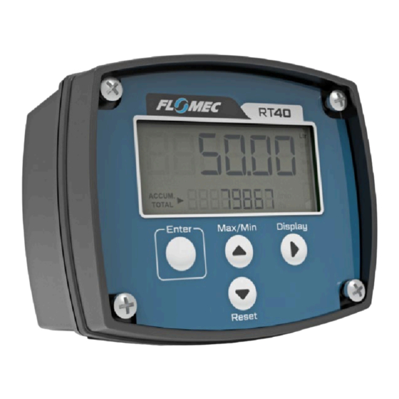
1. Introduction 1.1 Product Overview The RT40 Rate Totaliser is designed for computing and displaying volume and volumetric flowrate from a flowmeter with a pulse or frequency output. The instrument will display Flow Rate, Total and Accumulated Total in engineering units as programmed by the user. Simple flow chart programming with English prompts guides you through the configuration steps, greatly reducing the need to refer to the instruction manual. -
Page 5: Specifications
1.2 Specifications Glass reinforced Nylon (PA6) with a Polycarbonate lens, Santoprene Physical gasket, polyester decal. Enclosure provides an IP rating of IP65 Optional powder coated Aluminium enclosure Temperature Operating Temperature Range is -30 C ~ +80 C (-22 F ~ +176 Electrical Entries 3 entries - M16 x 1.5 Large dual line LCD with 6 characters 17mm high on top line, 8 characters... -
Page 6: Operation
The LCD backlight will automatically illuminate once external DC power is connected to the RT40. This feature can be overridden through the configuration menu to force the backlight to ‘OFF’. The backlight can also be set to flash when the flow alarm is triggered by setting the... -
Page 7: Keypad Function
RT40 will automatically adjust the settings so that no further input is required by the user (k-factors do not need to be changed). If the RT40 is displaying a Total in Litres this will be automatically converted to the new units of measure so that no data is lost. - Page 8 The minimum input frequency requirement for a flow rate display is 0.1Hz, this is also the default setting. With input frequencies below the Low Frequency Cut-Off the RT40 will not be able to display an instantaneous flow rate. Note that Totalisation is not affected by the Low...
- Page 9 When using a standard single channel flowmeter with an RT40 users will find that reverse flow in their pipe will produce the same flowmeter pulse signal as occurs during forward flow. This means that reverse flow will be counted by the RT40 as if the flow were still travelling ‘forwards’.
- Page 10 2.3.6 Display Backlight The display backlight will be automatically enabled upon connection of an external DC voltage supply in the range of 12-30V; the backlight is not available when operating on battery power. If it is required to reduce power consumption while operating on external DC power the backlight can be overridden by the user.
- Page 11 5 years of battery life; average conditions are considered to be a reed switch input from a FLOMEC flowmeter with no outputs used. High input frequencies (~1kHz and higher) from a turbine flowmeter will reduce battery life by around 20%, and operation of a battery powered scaled pulse output will reduce battery life by approximately 50%.
-
Page 12: Mechanical Installation
3. Mechanical Installation 3.1 General Requirements Installation of this product should only be carried out by suitably qualified/trained personnel with an understanding of local regulations regarding electrical installations. It is recommended that the instrument is installed in a location where it is shielded from extreme varying weather conditions, and from chances of physical impact. -
Page 13: Panel Mounting
3.5 Panel Mounting Mounting of the instrument in a panel requires a 95mm x 76mm (3.75” x 3.0”) rectangular hole to be cut in the panel – panels thicker than 3.2mm (1/8”) should substitute longer screws. The enclosure gasket must be used to maintain weather protection when panel mounted. It is possible to maintain the IP65 rating for the outside of the panel with an accurately cut hole and a flat/smooth panel. -
Page 14: Electrical Installation
4. Electrical Installation All wiring connections should be made with good quality shielded instrument cable; wiring between terminals which are inside the instrument enclosure, or between a flowmeter and an integrally mounted instrument may use non-shielded wire. Cable shields or drain wires should be connected to the instrument ground (GND) at the instrument end only –... -
Page 15: Input Connections
4.2 Input Connections The input type must be set in the software before the below wiring connections will function. 4.2.1 Reed Switch Input 4.2.2 NPN Sensor Input (Hall Effect) - Page 16 4.2.3 Voltage Pulse Input (Paddle-wheel Meters) 4.2.4 Variable Reluctance Coil Input (Turbine Meters)
- Page 17 4.2.5 Quadrature Pulse Input (Hall) Note: If negative flow is displayed during “forward flow” conditions, swap the wiring connections for signal 1 and signal 2 (Quad). 4.2.6 QS200 / QS100 – 2 Wire Pulse...
-
Page 18: Output Connections
4.3 Output Connections 4.3.1 NPN Pulse or Alarm Output 4.3.2 NPN Alarm Output to Relay... - Page 19 4.3.3 Remote Switches External switches may be connected to the RT40 display to allow remote access to button functions, or to allow use of heavy industrial push buttons in environments where the standard switches may break or wear. Momentary normally open (NO) switches MUST always...
-
Page 20: Programming Parameters
By default, the PIN protection function is off. When entering the programming menu for an RT40 display which does not have a PIN enabled the user will be asked if they want to enter a PIN. Selecting “N” will leave the PIN protection feature OFF and will progress to the next stage of the programming menu. -
Page 21: Time-Base For Rate
Display Unit Conversion Factor (units / Litre) Display Litres Ltr (right of screen) US Gallons 0.264172 Ga (right of screen) Cubic Metres 0.001 (right of screen) Pounds User prompt lbs (right of screen) Kilograms User prompt kgs (right of screen) Imperial Gallons 0.219969 Ga (right of screen) -
Page 22: Input Signal Configuration
The default input type is “SINGLE” and is the correct input type for most flowmeters. If the RT40 is to be used with a flowmeter with quadrature output – a 2 channel signal which typically has 4-wires – “QUAD” should be selected, which will allow the RT40 to detect flow direction and calculate both forward and reverse flow. -
Page 23: Calibration Data
If data is entered for the first 3 points of calibration, and point 4 is entered as zero Hz then points 4 and 5 will be disabled and the RT40 will operate with 3 points of calibration. -
Page 24: Digital Output
5.8 Digital Output The digital output function is configurable for either a pulse output according to totalised flow, or an alarm output according to flowrate. The pulse output can be configured for an unscaled pulse or a scaled pulse, and the alarm can be configured for notification of high flowrates, low flowrates, or a combination of both. -
Page 25: Advanced Options Menu
5.8.3 Flow Alarm The Alarm output is enabled by selecting ‘ALARM’ from the digital output menu. The alarm output may be configured as a ‘High Alarm’ which will trigger in the event the flow rate exceeds the alarm set-point, a ‘Low Alarm’ which will trigger in the event the flow rate drops below the set-point, or a ‘High/Low Alarm’... - Page 26 The default value for the low frequency cut-off is 0.1Hz, and the parameter is adjustable from 0.1Hz up to 9.9Hz. It is not possible to enable a rate display for input frequencies below 0.1Hz. 5.9.3 Rate Calculation Pulses The purpose of the ‘Rate Calculation Pulses’ parameter is to determine the number of input pulses which are used in calculation of the flow rate;...
-
Page 27: Diagnostics
The serial number screen allows the user to see the serial number for their product. This number will also be shown on the physical label on the outside of the display enclosure. This number may be needed if you contact FLOMEC for technical assistance. 6.1.2 Input Frequency The input frequency screen will display the current input frequency in Hertz on the LCD screen. -
Page 28: Troubleshooting Summary
6.2 Troubleshooting Summary Symptom Probable Cause Corrective Action Incorrectly entered calibration data Electrical interference See 6.3.2 below INACCURATE READINGS Mechanical or electrical Contact the manufacturer if a fault with flowmeter product fault is identified Flowmeter requires recalibration Incorrect configuration See 6.3.1 below TOTAL NOT COUNTING WITH Incorrect wiring... -
Page 29: Troubleshooting Steps
6.3.1 Total Not Counting If the total display on the RT40 is not counting it will be necessary to determine if the cause of the fault is a flowmeter failure, failure of the RT40 itself, or incorrect setup of the RT40. - Page 30 6.3.3 Inaccurate Readings If the RT40 display is showing inaccurate readings of flowrate or total volume the possible causes are; incorrect configuration settings in the RT40, electrical noise, or a faulty flow meter. Please follow the below steps to troubleshoot this issue.
- Page 31 6.3.5 No Pulse Received at PLC or FMS If your RT40 is correctly displaying a flowrate and total but you are not receiving a pulse signal at your PLC, fuel management system, or any other device with a frequency input, this may be due to a fault at either the RT40, the external device, or incorrect/broken wiring.
-
Page 32: Programming Flowchart
7. Programming Flowchart... -
Page 36: Spare Parts
Includes: Part No: Front Housing Kit Front housing (glass reinforced nylon), screen 1502070 (GRN) cover, FLOMEC decal, screws, and gasket Front Housing Kit Front housing (aluminium), screen cover, 1502037 (Aluminium) FLOMEC decal, screws, and gasket Rear housing for meter mounted instrument Meter Mount Rear (glass reinforced nylon);... - Page 37 Notes:...
- Page 38 Notes:...
- Page 39 Notes:...
- Page 40 Service & Warranty For Technical Assistance, warranty For Technical Assistance, warranty replacement or repair in North or replacement or repair outside North South America contact your Flomec America contact your Flomec Distributor or contact Distributor or contact Great Plains Industries, Inc.
Need help?
Do you have a question about the RT40 and is the answer not in the manual?
Questions and answers