
Related Manuals for Copeland Case Controller 200


Summary of Contents for Copeland Case Controller 200
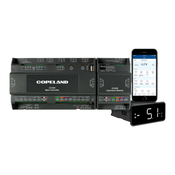
- Page 1 USER GUIDE Case Controller 200 (CC200) and Case Display Firmware 1.03F01 Installation and Operation Manual...
- Page 2 CC200 FIRMWARE VERSION 1.03F01 The enclosure should never be opened. Warranty void of seal is tampered with or removed. FCC COMPLIANCE NOTICE The CC200 Display device complies with Part 15 of the FCC Rules. Operation is subject to the following two conditions: (1) this device may not cause harmful interference, and (2) this device must accept any interference received, including interference that may cause undesired...
-
Page 3: Table Of Contents
3.10 PWM EEV Wiring ............................. 15 Pulse Width Modulation EEV Connections ............................15 3.11 CC200 Expansion Module Mounting and Installation ............... 16 CC200 Expansion Module Specifications ............................... 17 3.12 CC200 Case Display Wiring ........................17 026-1740 R18 CC200 User Guide ©2024 Copeland LP. - Page 4 4.9 Electric Evaporator Pressure Regulator (EEPR) ..................22 4.9.1 Pressure Mode ..............................22 4.9.2 Floating SST Algorithm ..........................22 4.9.3 Sensor Redundancy ............................23 4.10 Lighting Control .............................. 23 4.11 Door Switch............................... 23 026-1740 R18 CC200 User Guide ©2024 Copeland LP.
- Page 5 CC200 BACnet IP Ethernet Cabling................................32 BACnet IP Ethernet Cable Recommended Cable Choices ......................32 BACnet IP Ethernet Cable Recommended Connectors and Crimp Tools ................32 BACnet IP Ethernet Cable General Specifications ..........................32 026-1740 R18 CC200 User Guide ©2024 Copeland LP.
- Page 6 8.2 BACnet E3 Setup for ETH 1 IP Network ...................... 48 Add and Connect Case Controllers ................................50 8.3 Modbus E3 Setup .............................. 52 Modbus COM Port Setup ....................................52 Add and Connect Case Controllers ................................53 026-1740 R18 CC200 User Guide ©2024 Copeland LP.
- Page 7 Appendix A: CC200 Parameters ........................71 Appendix B: Dimensions ............................94 Appendix C: Door Switch Mounting and Wiring Hinged Doors ............95 Appendix D: Door Switch Mounting and Wiring Sliding Doors .............96 Appendix E: 118-4101 Door Switch Dimensions ..................97 026-1740 R18 CC200 User Guide ©2024 Copeland LP.
- Page 8 • Fit the transmitter where it is accessible by the End User for troubleshooting and replacement. The instrument must not be opened. • In case of failure or faulty operation send the instrument back to the distributor or to “Copeland” (see address) with a detailed description of the fault.
-
Page 9: Introduction
The controller can be integrated into a Supervisory Controller and is currently integrated into the Copeland E2E and E3 Supervisory Controllers using BACnet and Modbus. While integrated with E2E or E3, the CC200 runs completely stand-alone and requires no Supervisory Controller instructions or commands. -
Page 10: Cc200 Overview
• Three color-coded temperature inputs for discharge air, return air, and defrost termination plus coil out temperature. • One defrost current transducer input for heater amperage monitoring. • Two auxiliary analog inputs: user-configurable purpose. • Expansion port connector for easily adding additional IO via CC200 Expansion Module. 026-1740 R18 CC200 User Guide ©2024 Copeland LP. - Page 11 RJ45 Ethernet 1 used for case lineup peer communication and BACnet IP. ETH2 RJ45 Ethernet 2 used for case lineup peer communication and BACnet IP. Universal Serial Bus female connector. Copeland use only. Auxiliary Port Connection to CC200 expansion module if present.
-
Page 12: Expansion Module Overview
Winding 2 connection for stepper valve motor wiring harness. 35 - 36 STEPPER VALVE W1 Winding 1 connection for stepper valve motor wiring harness. STEPPER + 12V 12V for unipolar stepper motors. 026-1740 R18 CC200 User Guide ©2024 Copeland LP. -
Page 13: Case Display Overview
Shortcut to Modbus and BACnet addressing menu, long press to enter Modbus and BACnet settings menu. Reboot CC200 Reboot CC200 action icon, long press to reboot CC200 controller. More Available More pages indicator, present when more content is available by swiping. Units Celsius/Fahrenheit temperature engineering unit label. ©2024 Copeland LP. 026-1740 R18 CC200 User Guide... -
Page 14: Powering And Wiring Cc200
Powering and Wiring CC200 An overall connection detail is shown below for reference. Detailed instructions on powering and wiring are included in the following sections. CC200 Wiring and Connections 026-1740 R18 CC200 User Guide ©2024 Copeland LP. -
Page 15: Cc200 Power Wiring
3.1 CC200 Power Wiring CC200 must be powered by an Copeland CC200 24VDC power supply P/N 318-3183. Connect the 24VDC power supply to the CC200 by connecting two (2) wires from the power supply port terminals labeled -V and +V to the CC200 power 24VDC connector port numbers 72 (+) and 73 (-). -
Page 16: Cc200 Output Wiring
AO2 (AO) 4-20mA or 0-10VDC Future Light Dimming 4 1(+) – 42(-) 1(Jmp) – 2(Line) – 3(Valve) Jump Terminals 1 TRIAC 20W Max 24/120/230Vac PMW Valve and 2 ONLY for 24Vac Valve 026-1740 R18 CC200 User Guide ©2024 Copeland LP. -
Page 17: Cc200 Input Wiring
Step 1: Make sure the power is OFF to the CC200 Main Controller. Step 2: Determine what sensors will be needed and wire per the specification above. If the sensor needs to be extended, Copeland only supports heat shrink and solder. Step 3: Determine how many coils are on the cases. -
Page 18: Coil Outlet Sensor Mounting
50 ft. If manufacturer harness must be extended, join wires with heat shrink and solder. Belden 28326AS Copeland P/N 135-2832 or Belden 8771 Copeland P/N 135-8771 or equivalent Pressure Transducer 3 conductor shielded 22 AWG or larger cable may be used to extend length to a maximum of 50 ft. -
Page 19: Pressure Transducer Mounting
○ When WM EEV is used, EEPR is always located on CC200 Main Controller Stepper terminals. ○ When Stepper EEV is used, EEPR is located on the last Expansion Module Stepper terminals. ©2024 Copeland LP. 026-1740 R18 CC200 User Guide... -
Page 20: Expansion Module Remote Mounting
DIN rail, the CC200 Expansion Modules may be mounted near the CC200 Main Controller using extension harness(s) made from Belden 28326AS Copeland P/N 135-2832 or Belden 9418 Copeland P/N 135-9418 or equivalent 4 conductor shielded 18 AWG cable with total length of cable(s) from CC200 Main Controller to all CC200 Expansion Modules not to exceeded 10 feet. -
Page 21: Cc200 Stepper Valve Wiring
Step 1: Make sure the power is OFF to the CC200 Main Controller and Expansion Module. a. The wiring specification above is only for Sporlan Bipolar CDS valves or Sporlan SER EEV valves. b. If other manufacturer valves are used, refer to the manufacturer’s specification and contact Copeland for instructions on how to terminate. -
Page 22: Cc200 Stepper Valve Specifications
3.9 Supported Stepper Valve List The table below shows supported valves with recommended parameter values to configure each valve. For any valves not listed, obtain the valve manufacturer data sheet and contact Copeland for details on how to operate the valve with CC200. -
Page 23: Pwm Eev Wiring
Step 3: Refer to the below diagram for 120V valve coils only, complete the terminations as shown in the diagram. The PWM valve ground wire or terminal should be securely connected to 120VAC supply circuit ground. Do not connect PWM valve ground wire to any CC200 terminal. ©2024 Copeland LP. 026-1740 R18 CC200 User Guide... -
Page 24: Cc200 Expansion Module Mounting And Installation
24VDC supply power to the CC200 Main Controller. Once connected, the Expansion Module PWR ON LED will illuminate green indicating supply power is present. Connecting Two Expansion Modules and Terminations 026-1740 R18 CC200 User Guide ©2024 Copeland LP. -
Page 25: Cc200 Expansion Module Specifications
Polarity Sensitive Wire Specs for Extending Inputs and Valves General Cable 92454A Copeland P/N 135-0600 or Belden 8761 Copeland P/N 035-0002 or equivalent 2 conductor shielded 22 AWG or larger cable may be used to extend length to a Analog Temp Sensors or Digital maximum of 50 ft. - Page 26 CC200 Case Display Dimensions CC200 Case Display Wiring 026-1740 R18 CC200 User Guide ©2024 Copeland LP.
-
Page 27: Control Logic Overview
CC200 has parameters that inform the controller what and rack system manufacturers is not recommended or equipment and valves are present and based on these supported by Copeland. selections CC200 will use the optimum regulation strategy to control the evaporator and air temperature. Set the parameter To activate and use the superheat optimization feature: COMPRESSION TYPE, EXP. -
Page 28: A2L Refrigerants
Copeland failures. Typically in a supermarket refrigeration system cases pressure transducer. The refrigerant type selection is made in a lineup defrost at the same time, CC200 case lineup with the parameter Refrigerant in the System Setup group. -
Page 29: Defrost Control
During defrost the fan can remain on or off depending on parameter selection to accommodate different case types. ©2024 Copeland LP. 026-1740 R18 CC200 User Guide... -
Page 30: Two Speed And Variable Speed Fans
SST setpoint. For example, an SST setpoint of -10° with a float band of 4° will allow the algorithm to adjust the SST setpoint from -12° to -8°. 026-1740 R18 CC200 User Guide ©2024 Copeland LP. -
Page 31: Sensor Redundancy
The fan relay output will remain on, but the auxiliary fan 2 speed output will be deactivated and the variable speed analog output will go to its minimum speed. ©2024 Copeland LP. 026-1740 R18 CC200 User Guide... -
Page 32: A2L Shutdown
Circuit suction temperature sensor Circuit Suction for overall circuit lineup superheat Temperature monitoring and alarming. All input sensors have an option to enter a sensor value offset via parameter settings. 026-1740 R18 CC200 User Guide ©2024 Copeland LP. -
Page 33: Relay Outputs
This alarm will reset when the source of the refrigerant leak detection has been resolved. This alarm will persist through reboots until it is resolved. ©2024 Copeland LP. 026-1740 R18 CC200 User Guide... -
Page 34: Cc200 Case Display
Tap PRG to enter a group and for the as the first parameter group. view its parameters. The following grou ps and parameters are available for editing. CC200 Case Display PRG Screen 026-1740 R18 CC200 User Guide ©2024 Copeland LP. - Page 35 Update Enable - Trigger display firmware download from CC200 Yes - Start the .fw download from CC200 No - Disable OTAP OTAP - Enable OTAP mode (Copeland use only) Yes - Enable OTAP ©2024 Copeland LP. 026-1740 R18 CC200 User Guide...
-
Page 36: Action Icons
Long press again for 3 seconds to turn off Bluetooth® radio Long press for 3 seconds to jump to parameter group, “ ” No function. Long press for 5 seconds to reboot CC200. 026-1740 R18 CC200 User Guide ©2024 Copeland LP. -
Page 37: The Bacnet Network
Section 6.5, Configuring BACnet Settings on the CC200 Case Display Each CC200 ships from the factory with the router disabled. The figure below gives an overview of the required BACnet network topology. Network Topology Overview for E2 ©2024 Copeland LP. 026-1740 R18 CC200 User Guide... -
Page 38: Bacnet Ip With E3 Ethernet Ports
CC200 subnet mask defaults to 255.0.0.0 already. Each CC200 must also have a unique BACnet device object identfier, which will be automatically assigned by following the steps in Section 6.5, Configuring BACnet Settings on the CC200 Case Display 026-1740 R18 CC200 User Guide ©2024 Copeland LP. - Page 39 • Change all BACnet IP CC200 IP address octet 1 to 192 as outlined in Section 6.5, Configuring BACnet Settings on the CC200 Case Display BACnet IP Devices for Connection to BACnet IP with E3 Ethernet Port 1 Cabling and Details ©2024 Copeland LP. 026-1740 R18 CC200 User Guide...
-
Page 40: Cc200 Bacnet Ip Ethernet Cabling
AWG accommodate the Ethernet cable AWG. BACnet IP Ethernet Cable Recommended Cable Choices • Copeland recommends the following cable options or an exact equivalent that meets or exceeds all of the general specifications below: ¾ General Cable GenSPEED 5000 CAT5e CMR 24 AWG/4 pair unshielded twisted pair ¾... -
Page 41: Bacnet Router Rs485 Detail
“comm loop” per supervisor serial port is allowed. A maximum total of 64 CC200 BACnet devices across all E2E serial ports is allowed. The router CC200 and all connected BACnet IP CC200s count towards the maximum. Copeland specs General Cable 92454A (Copeland P/N 135-0600) shielded twisted pair cables for use as BACnet MS/TP RS-485 wiring. -
Page 42: Bacnet Router Rs485 Specifications
Installers must use the shielded twisted cable listed below so that ASHRAE and EIA-485 compliance is maintained for all BACnet installations. • RS485 Cable Type Requirement: Copeland P/N 135-0600 or Echelon Level 4. • RS485 Cable Specs: ¾ Shielded Twisted Pair ¾... -
Page 43: Configuring Bacnet Settings On The Cc200 Case Display
BACnet changes. Once selected push and hold PRG for 3 seconds to save the edit. Once saved the value will flash, display will beep and return to the Sav. After Sav is set to Yes the CC200 will automatically reboot to initialize BACnet settings. ©2024 Copeland LP. 026-1740 R18 CC200 User Guide... -
Page 44: Non-Router Devices
BACnet changes. Once selected push and hold PRG for 3 seconds to save the edit. Once saved the value will flash, display will beep and return to the Sav. After Sav is set to Yes the CC200 will automatically reboot to initialize BACnet settings. 026-1740 R18 CC200 User Guide ©2024 Copeland LP. -
Page 45: Modbus Network
Modbus and Case Lineup for E2 Ring and star topologies must be avoided and are not supported under any circumstance. Integration files for Copeland E3, E2E and Site Supervisor are available for use. RS485 Port B on the CC200 will be used for Modbus RS485 communications, see wiring detail below for detailed connection information. - Page 46 Modbus and Case Lineup for E2 026-1740 R18 CC200 User Guide ©2024 Copeland LP.
- Page 47 Modbus and Case Lineup for E3 ©2024 Copeland LP. 026-1740 R18 CC200 User Guide...
- Page 48 RS485 Modbus Network Wiring for E2 RS485 Modbus Network Wiring for E3 026-1740 R18 CC200 User Guide ©2024 Copeland LP.
-
Page 49: Configuring Modbus Settings On The Cc200 Case Display
Once yes is selected, push and hold PRG for three (3) seconds to save the edit. Once saved, the value will flash, the display will beep and return to Sav. After Sav is set to yes the CC200 will automatically reboot to initialize the Modbus settings for proper communication. ©2024 Copeland LP. 026-1740 R18 CC200 User Guide... -
Page 50: E2 Setup
• Reporting of case controller-related alarms • The ability to log case controller data in an E2E logging group • The ability to shut down refrigeration for walk-in boxes in event of a refrigerant leak event (available if a Copeland leak detection panel is used) •... -
Page 51: Configure E2E Bacnet Settings
Press on the keyboard to access the Network Summary screen. The number of Case Controller units added in Step 3 should now be visible in the Network Summary screen. ©2024 Copeland LP. 026-1740 R18 CC200 User Guide... -
Page 52: Commissioning The Device In E2E
BACnet Device ID is set. The E2E will display a list of the devices discovered during Then press the button to save and exit back to the the scan: Network Summary screen: 026-1740 R18 CC200 User Guide ©2024 Copeland LP. -
Page 53: E2 Modbus Setup
Data Size - Leave this field at the default value (8). c. Parity - Leave this field at the default value (None). d. Stop Bits - Leave this field at the default value (1). Press to save changes and exit. ©2024 Copeland LP. 026-1740 R18 CC200 User Guide... -
Page 54: Commissioning The Cc200 In E2E
Modbus address, the name will appear next transition from Unknown to a green Online status to the left of the Modbus address number. indicating successful communication is taking place. Select the Modbus address of the device and press 026-1740 R18 CC200 User Guide ©2024 Copeland LP. -
Page 55: E3 Setup - Bacnet And Modbus
General System Properties. Select the COM Ports tab and select the COM port which the CC200 network cable is wired to. Configure the following BACnet settings for the port: ©2024 Copeland LP. 026-1740 R18 CC200 User Guide... -
Page 56: Bacnet E3 Setup For Eth 1 Ip Network
Set a unique BACnet device ID for ETH 0 and ETH 1. CC200 device ID’s start in the 10,000 range and increase from there. Using a value well below 10,000 for E3 is safe. 026-1740 R18 CC200 User Guide ©2024 Copeland LP. - Page 57 Add and Connect Case Controllers add CC200s and bring them online with E3. At the step where the Port ID is selected, choose BACnet IP-ETH1 and then start the scan to discover available case controllers. ©2024 Copeland LP. 026-1740 R18 CC200 User Guide...
-
Page 58: Add And Connect Case Controllers
Select the BACnet Port ID for the CC200 network you wish to bring online. A scan will start to discover available BACnet CC200s on the serial port. 026-1740 R18 CC200 User Guide ©2024 Copeland LP. - Page 59 Repeat steps 4 and 5 for the remaining case controllers, setting the corresponding address for each. After a scan for devices, for a sorted list of CC200s, go to the home page and then return to the Control Inventory NOTICE page. ©2024 Copeland LP. 026-1740 R18 CC200 User Guide...
-
Page 60: Modbus E3 Setup
Stop Bits - Leave this field at the default value (1). e. Response Delay- Leave this field at the default value (0). Click Save and proceed to adding and connecting case controllers in the next section. 026-1740 R18 CC200 User Guide ©2024 Copeland LP. -
Page 61: Add And Connect Case Controllers
Click the checkbox to confirm the address, the case controller should transition from Unknown to Online. Repeat steps 4 and 5 for the remaining case controllers, setting the corresponding address for each. ©2024 Copeland LP. 026-1740 R18 CC200 User Guide... -
Page 62: Cold Chain Connect Mobile Application
Cold Chain Connect Mobile Application Cold Chain Connect is a mobile application for connecting to the Copeland CC200 refrigerated case controller. This section is a guide for using the Cold Chain Connect App to set parameters, graph inputs and outputs, set service overrides, and view alarms. -
Page 63: How To Activate Bluetooth® On The Cc200 Case Display
Chain Connect will scan for nearby CC200 controllers and • Case Superheat • Presures available controllers will be displayed as shown in the below • Status of the relay outputs • Alarms graphic. ©2024 Copeland LP. 026-1740 R18 CC200 User Guide... -
Page 64: How To Set Parameters
To cancel the Manual Defrost or Emergency Defrost: • Select Manual Defrost again and now, a pop-up window to End Manual Defrost will appear. Select End Manual Defrost and the defrost is now cleared. 026-1740 R18 CC200 User Guide ©2024 Copeland LP. -
Page 65: Calibrate Valve
Restart CC200 command from the list. A pop-up will be shown to confirm the action. The CC200 will perform a soft reboot and status information will be temporarily unavailable in the Cold Chain Connect dashboard. ©2024 Copeland LP. 026-1740 R18 CC200 User Guide... -
Page 66: Real-Time Graphs
An alarm icon will appear next to any piece of data in the Case tab that has an active alarm. Tap the icon next to the data point to see the description. 026-1740 R18 CC200 User Guide ©2024 Copeland LP. -
Page 67: Info
Connection a. Select at the bottom of the application. • You will see a pop-up windown asking you to Disconnect. • Select Yes, Disconnect and you will be disconnected from the Case. ©2024 Copeland LP. 026-1740 R18 CC200 User Guide... -
Page 68: Configuring Cc200 Parameters
PWM Short Cycle to (100% - PWM Short Cycle). To obtain maximum capacity, the PWM valve percentage will step from (100% - PWM Short Cycle) to 100% to prevent short cycle of valve at top end of control range (limits minimum OFF time of Valve during the Pulse Period). 026-1740 R18 CC200 User Guide ©2024 Copeland LP. - Page 69 Superheat Deadband Deadband around superheat setpoint (+/- half) The Copeland default value is sufficient unless adjustments to evaporator performance are required. Max Pulldown Time This duration specifies the maximum amount of time the case can remain in a post defrost pulldown.
- Page 70 The amount of steps to open the valve after calibration. Generally 4 steps or more are needed to relax valve seat tension. Entering a number of steps too large could result in refrigerant flow with valve at 0%. 026-1740 R18 CC200 User Guide ©2024 Copeland LP.
- Page 71 Entering a number of steps too large could result in refrigerant flow with valve at 0%. Min Opening Minimum allowed opening percentage during superheat regulation. A value of 0 is recommended for properly sized valves. ©2024 Copeland LP. 026-1740 R18 CC200 User Guide...
- Page 72 When the fan feedback status does not match the fan command value for FAN PROOF DELAY, a command failure alarm will result. Defr Proof On When defrost heater amperage rises above the DEFR PROOF ON level the defrost heater shall be considered ON. 026-1740 R18 CC200 User Guide ©2024 Copeland LP.
- Page 73 Select the fan current transducers high end amperage value if an aux AI is set to Fan CT. Only 4-20mA signal CT’s are supported. Offsets An offset parameter is provided for each sensor for service purposes. For most situations no offset is required. Enter an offset if needed to calibrate the sensor. ©2024 Copeland LP. 026-1740 R18 CC200 User Guide...
- Page 74 Each digital input function has an associated active state parameter to determine what state of the input should Active State result in an ON value in CC200 logic. See Section 4.4, Dual Temperature Cases of this manual for active state for digital inputs. 026-1740 R18 CC200 User Guide ©2024 Copeland LP.
- Page 75 No. See Section 6, The BACnet Network this manual for a detailed overview of the BACnet network and BACnet router. ©2024 Copeland LP. 026-1740 R18 CC200 User Guide...
-
Page 76: Technical Specifications And Part Numbers
Description Primary Power 120VAC Secondary Power 24VDC 24VDC 60W CC200 Power Requirements CC200 Power Supply Copeland P/N 318-3183 Required Power Supply Power Supply Terminals 2 (-V) & 3 (+V) CC200 Power Terminals 72(+) --73(-) -- 71(Earth) Wire Spec 16AWG or larger diameter wire Max Wire Length 20”... -
Page 77: Cc200 Case Expansion Module Specifications
-40°F to185°F / -40°C to 85°C Relative Humidity 20 to 85 RH% (non-condensing humidity) Protection Body: IP20; Front: IP65 Pollution Degree Points CC200 Terminals to CC200 Display Terminals 27(-) to 5(-) 28(+) to 4(+) 29(VNR) to 3(VNR) ©2024 Copeland LP. 026-1740 R18 CC200 User Guide... -
Page 78: Part Numbers For Ordering
CC200 Walk In Defrost CT, 50A (4-20mA) CC200 Case Display Bracket 302-0100 Note: For use with 318-3182 CC200 Case Display 302-0105 Deli Case Display Bracket For optimal performance of the CC200, Copeland parts are required. 026-1740 R18 CC200 User Guide ©2024 Copeland LP. -
Page 79: Appendix A: Cc200 Parameters
Enter the BACnet max master of the Max Master None BACnet controller Enter number of application protocol APDU Retries None BACnet data unit retries Enter application protocol data unit APDU Timeout Seconds BACnet timeout 026-1740 R18 CC200 User Guide ©2024 Copeland LP. - Page 80 Case ID Select the case letter List a, b, c, d, e, f, g, h Data Bits Modbus message number of data bits None Parity Modbus message parity type None even, odd, none 026-1740 R18 CC200 User Guide ©2024 Copeland LP.
- Page 81 Rack-Fixed Cap - Parallel rack system with no and later. digital unloader or variable speed motor. Rack-Variable Cap - Parallel rack system with at least one compressor able to vary capacity by motor speed or variable unloader. 026-1740 R18 CC200 User Guide ©2024 Copeland LP.
- Page 82 Select the type of air sensor used for Discharge Air Control Sensor List Sys. Setup temperature control Return Air Average Select the sensor combination method Case Temp. Combination List Sys. Setup Minimum (avg, min, max) Maximum 026-1740 R18 CC200 User Guide ©2024 Copeland LP.
- Page 83 Setpoints available in version CC200 1.02F02 and later. optimization mode Max Pulldown Time The maximum time allowed in pulldown Minutes Setpoints Door Disables Refrig. Door opening disables refrigeration List Setpoints No, Yes 026-1740 R18 CC200 User Guide ©2024 Copeland LP.
- Page 84 Minimum Maximum Defrost termination temperature Term. Temp. Setpoint Defrost setpoint The minimum time defrost must run Minimum Time Minutes Defrost before termination is allowed Maximum Time Defrost maximum allowed run time Minutes Defrost 026-1740 R18 CC200 User Guide ©2024 Copeland LP.
- Page 85 No, Yes Enable/disable EEPR control. Note: Enable EEPR parameter has been deprecated in CC200 1.01F01 List EEPR Disabled, Enabled Enable EEPR and superseded by EPR Type, use EPR Type to enable/disable EEPR usage. 026-1740 R18 CC200 User Guide ©2024 Copeland LP.
- Page 86 EEPR Step Rate EEPR valve step rate (steps/second) None EEPR Percentage of maximum steps to over Over Close Percent EEPR drive during calibration Relax Steps Reverse steps after overclose EEPR None EEPR 026-1740 R18 CC200 User Guide ©2024 Copeland LP.
- Page 87 EEV 3 Motor Type Valve motor type (Unipolar or Bipolar) List Bipolar EEV1-3 position at beginning of Start Position Percent regulation Start Hold Time Time to hold EEV1-3 in start position Seconds 1800 026-1740 R18 CC200 User Guide ©2024 Copeland LP.
- Page 88 EEV 2 Relax Steps procedure Minimum opening allowed during EEV 2 Min Opening Percent regulation EEV 3 Max Steps Maximum steps of the valve 10000 EEV 3 Step Rate Valve step rate (steps/ seconds) 026-1740 R18 CC200 User Guide ©2024 Copeland LP.
- Page 89 Lights switch ON when door is open List Lights No, Yes Lights switch ON when motion is Motion Lights On List Lights No, Yes detected On Duration Lights on duration for door or motion DI Minutes Lights 026-1740 R18 CC200 User Guide ©2024 Copeland LP.
- Page 90 Temp. Delay After Def. Minutes Alarms after each defrost cycle Low SH. Alarm Alarm setpoint for superheat Alarms Time delay before activating the low Low Sh. Alarm Delay Minutes Alarms superheat alarm 026-1740 R18 CC200 User Guide ©2024 Copeland LP.
- Page 91 1 Per Coil Not Used Rat Config Select return air configuration List AI Config. 1 Per Coil 1 Per Coil Select pressure transducer Pressure Config List AI Config. configuration 1 Per Case 026-1740 R18 CC200 User Guide ©2024 Copeland LP.
- Page 92 650 PSI Custom Note: 500, 650 and custom ranges are available in CC200 version 1.01F01 and higher. Defr CT Enable Select if defrost CT is used/not used List AI Config. Disabled, Enabled 026-1740 R18 CC200 User Guide ©2024 Copeland LP.
- Page 93 DAT 1 Offset Sensor offset for discharge air 1 AI Config. DAT 2 Offset Sensor offset for discharge air 2 AI Config. DAT 3 Offset Sensor offset for discharge air 3 AI Config. 026-1740 R18 CC200 User Guide ©2024 Copeland LP.
- Page 94 Offset for pressure transducer evap 1 PSIG AI Config. Pressure 2 Offset Offset for pressure transducer evap 2 PSIG AI Config. Pressure 3 Offset Offset for pressure transducer evap 3 PSIG AI Config. 026-1740 R18 CC200 User Guide ©2024 Copeland LP.
- Page 95 Alarm RO Act Select the active state for alarm RO List RO Config De-energize, Energize Door Alm. RO Act Select the active state for door alrm RO List RO Config De-energize, Energize 026-1740 R18 CC200 User Guide ©2024 Copeland LP.
- Page 96 Satellite 2 Defrost Term. Not Used Motion Door Leak Shutdown Exp Mod 1 DI Func. Expansion module 1 DI 1 function List DI Config. Service Satellite 1 Dual Temp. Satellite 2 Defrost Term. 026-1740 R18 CC200 User Guide ©2024 Copeland LP.
- Page 97 Sat 1 DI Act Select active state of satellite 1 DI List DI Config. Off, On Sat 2 DI Act Select active state of satellite 2 DI List DI Config. Off, On 026-1740 R18 CC200 User Guide ©2024 Copeland LP.
- Page 98 No, Yes Sat. 1 AO Invert Invert sat 1 analog output signal List AO Config No, Yes Sat. 2 AO Invert Invert sat 2 analog output signal List AO Config No, Yes 026-1740 R18 CC200 User Guide ©2024 Copeland LP.
- Page 99 The CC200, Expansion Module, and power supply are DIN rail mounted components. The CC200 display is mounted in a cut-out hole in a vertical panel and secured using the supplied mounting brackets. The dimensions of each component are shown below. CC200 Dimensions P/N 810-3180 026-1740 R18 CC200 User Guide ©2024 Copeland LP.
- Page 100 Appendix B: Dimensions CC200 Expansion Module Dimensions P/N 318-3181 026-1740 R18 CC200 User Guide ©2024 Copeland LP.
- Page 101 Appendix B: Dimensions CC200 Display Dimensions P/N 318-3182 026-1740 R18 CC200 User Guide ©2024 Copeland LP.
-
Page 102: Appendix B: Dimensions
Appendix B: Dimensions Appendix B: Dimensions 60-Watt Power Supply Dimensions P/N 318-3183 92-Watt Power Supply Dimensions P/N 318-3184 026-1740 R18 CC200 User Guide ©2024 Copeland LP. -
Page 103: Appendix C: Door Switch Mounting And Wiring Hinged Doors
If contact assemlby leads need to be If contact assemlby leads need to be extended use shielded 22AWG/2 cable: extended use shielded 22AWG/2 cable: Copeland PN 135-0600, Copeland PN Copeland PN 135-0600, Copeland PN 035-0002, Belden 8761 or equivalent. Heat 035-0002, Belden 8761 or equivalent. Heat shrink and solder splices. -
Page 104: Appendix D: Door Switch Mounting And Wiring Sliding Doors
If contact assemlby leads need to be If contact assemlby leads need to be extended use shielded 22AWG/2 cable: extended use shielded 22AWG/2 cable: Copeland PN 135-0600, Copeland PN Copeland PN 135-0600, Copeland PN 035-0002, Belden 8761 or equivalent. Heat 035-0002, Belden 8761 or equivalent. Heat shrink and solder splices. -
Page 105: Appendix E: 118-4101 Door Switch Dimensions
Appendix E: 118-4101 Door Switch Dimensions 026-1740 R18 CC200 User Guide ©2024 Copeland LP. - Page 106 The contents of this publication are presented for informational purposes only and they are not to be construed as warranties or guarantees, express or implied, regarding the products or services described herein or their use or applicability. Copeland reserves the right to modify the designs or specifications of such products at any time without notice.
Need help?
Do you have a question about the Case Controller 200 and is the answer not in the manual?
Questions and answers