
Subscribe to Our Youtube Channel
Related Manuals for Pfeiffer Vacuum MVP 010-3-1 DC


Summary of Contents for Pfeiffer Vacuum MVP 010-3-1 DC
- Page 1 OPERATING INSTRUCTIONS Translation of the Original MVP 010-3-1 DC Diaphragm Pump...
-
Page 2: Telegram Example
Dear Customer, Thank you for choosing a Pfeiffer Vacuum product. Your new diaphragm pump is designed to support you with its performance, perfect operation and without impacting your individual application. The name Pfeiffer Vacuum stands for high-quality vacuum technology, a comprehensive and complete range of top-quality products and first-class service. -
Page 3: Table Of Contents
Limits of use of the product Proper use Foreseeable improper use Personnel qualification 2.7.1 Ensuring personnel qualification 2.7.2 Personnel qualification for maintenance and repair 2.7.3 Advanced training with Pfeiffer Vacuum Product description Function 3.1.1 Interstage pumping 3.1.2 Actuator 3.1.3 Pumping system 3.1.4 Cooling... - Page 4 Status requests Reference value inputs Operation Putting the vacuum pump into operation Switching on the vacuum pump Configuring connections with Pfeiffer Vacuum parameter set 8.3.1 Configuring the digital outputs 8.3.2 Selecting the interfaces Operating modes 8.4.1 Normal operation 8.4.2 Stand-by operation 8.4.3 Speed actuator operation...
- Page 5 Warning messages for vacuum pump Tbl. 22: Spare parts Tbl. 23: Conversion table: Pressure units Tbl. 24: Conversion table: Units for gas throughput Tbl. 25: Technical data, MVP 010-3-1 DC Tbl. 26: Materials that make contact with the process media 5/52...
- Page 6 Pins of the D-Sub socket, 15-pin Fig. 9: Cross-linking via RS-485 interface Fig. 10: Connection options via interface RS-485 Fig. 11: Diaphragm head and valves Fig. 12: Spare parts of the inspection sets Fig. 13: Dimensions MVP 010-3-1 DC 6/52...
-
Page 7: About This Manual
Keep the manual for future consultation. 1.1 Validity These operating instructions are a customer document of Pfeiffer Vacuum. The operating instructions describe the functions of the named product and provide the most important information for the safe use of the device. The description is written in accordance with the valid directives. The information in these operating instructions refers to the product's current development status. -
Page 8: Stickers On The Product
About this manual Note 1.3.3 Stickers on the product This section describes all the stickers on the product along with their meaning. Rating plate Rating plate of the diaphragm pump Warning hot surface This sticker warns of injuries caused by high temperatures in case of touching without protection during operation. -
Page 9: Tbl. 2: Abbreviations Used In This Document
About this manual Abbreviation Meaning in this document Diaphragm vacuum pump n.c. not connected Mean sea level [P:xxx] Electronic drive unit control parameters. Printed in bold as a three-digit number in square brackets. Frequently displayed in conjunction with a short description. Example: [P:312] software version Polyamide Protective earth (earthed conductor) -
Page 10: Safety
Safety 2 Safety 2.1 General safety information The following 4 risk levels and 1 information level are taken into account in this document. DANGER Immediately pending danger Indicates an immediately pending danger that will result in death or serious injury if not observed. ►... - Page 11 Safety Risks during installation DANGER Danger to life from electric shock Power supply packs that are not specified or are not approved will lead to severe injury to death. ► Make sure that the power supply pack meets the requirements for double isolation between mains input voltage and output voltage, in accordance with IEC 61010-1 IEC 60950-1 and IEC 62368-1.
-
Page 12: Safety Precautions
Safety CAUTION Danger of burns on hot surfaces Depending on the operating and ambient conditions, the surface temperature of the vacuum pump can increase to above 70 °C. ► Provide suitable touch protection. Risks during maintenance, decommissioning and in the event of malfunctions WARNING Health hazard through poisoning from toxic contaminated components or devices Toxic process media result in contamination of devices or parts of them. -
Page 13: Limits Of Use Of The Product
► Use the vacuum pump for vacuum generation only. ► Adhere to the installation, commissioning, operating, and maintenance instructions. ► Do not use any accessory parts other than those recommended by Pfeiffer Vacuum. 2.6 Foreseeable improper use Misuse of the product invalidates all warranty and liability claims. Any use that is counter to the purpose of the product, whether intentional or unintentional, is regarded as misuse, in particular: ●... -
Page 14: Personnel Qualification
● Connection to devices with exposed live parts ● Connecting to sockets without earthing contact ● Using lubricants not specified by Pfeiffer Vacuum ● Using pipes to lift the vacuum pump ● Use of accessories or spare parts that are not listed in these instructions ●... -
Page 15: Personnel Qualification For Maintenance And Repair
─ Customer with Pfeiffer Vacuum service training ─ Pfeiffer Vacuum service technician 2.7.3 Advanced training with Pfeiffer Vacuum For optimal and trouble-free use of this product, Pfeiffer Vacuum offers a comprehensive range of courses and technical trainings. For more information, please contact Pfeiffer Vacuum technical training. -
Page 16: Product Description
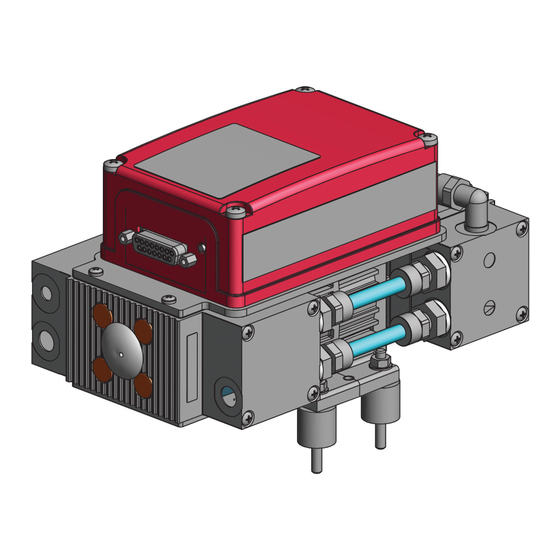
Product description 3 Product description 3.1 Function Diaphragm pumps are dry compressing positive displacement pumps. The movement of diaphragms generates a periodic change of the suction chamber volume. The gas flow causes the valves to open and close automatically. The pump unit is directly connected to the drive motor. Fig. -
Page 17: Actuator
Connection description of the electronic drive unit 3.3 Identifying product ► To ensure clear identification of the product when communicating with Pfeiffer Vacuum, always keep all of the information on the rating plate to hand. ► Learn about certifications through test seals on the product or at www.tuev-sued.de. -
Page 18: Transportation And Storage
Transportation and Storage 4 Transportation and Storage 4.1 Transporting the vacuum pump WARNING Danger of serious injury due to falling objects Due to falling objects there is a risk of injuries to limbs through to broken bones. ► Take particular care and pay special attention when transporting products manually. ►... -
Page 19: Installation
NOTICE Property damage from contaminated gases Pumping gases that contain contamination damages the vacuum pump. ► Use suitable filters or separators from the Pfeiffer Vacuum range of accessories, to protect the vacuum pump. Installation and operation of accessories Pfeiffer Vacuum offers a series of special, compatible accessories for its diaphragm pumps. -
Page 20: Establishing The Electric Connection
► Install a suitable exhaust line. ► Wear hearing protection. Condensate separator Pfeiffer Vacuum recommends installing a condensate separator, with condensate drain at the lowest point of the exhaust line. Procedure 1. Check the installed silencer for free passage. -
Page 21: Establishing Electric Connection
Installation Procedure 1. Use a suitable grounding cable to divert applicative interferences. 2. Route the connection in accordance with locally applicable provisions. 3. On the vacuum pump, use the designated ground terminal on the fixing plate (M4 female thread). 5.4.2 Establishing electric connection DANGER Danger to life from electric shock Power supply packs that are not specified or are not approved will lead to severe injury to death. - Page 22 ► Insert the connection cable into the connection "DC out" on the power supply pack and close the bayonet lock. ► If you are using a Pfeiffer Vacuum control unit: Connect the “RS-485” connector to the control unit using a suitable extension cable.
-
Page 23: Interfaces
The following specifications are the factory settings for the electronic drive unit. Configuring “remote” interface ► Utilize the screened plug and cable. ► Configure the inputs and outputs via the Pfeiffer Vacuum parameter set. Fig. 8: Pins of the D-Sub socket, 15-pin Function... -
Page 24: Voltage Supply
Pin assignment of the D-Sub socket, 15-pin 6.1.1 Voltage supply Input/pin 1 The electrical connection is made using a connection cable from the Pfeiffer Vacuum accessory range or, by the customer, at pin 1 and pin 15. +24 V DC* output/pin 7 A connection with +24 V DC to pin 7 (active high) activates inputs 2 to 6. -
Page 25: Rs-485
Tbl. 7: Output DO2/pin 9 6.1.4 RS-485 Connecting RS-485 via D-Sub ► Connect a Pfeiffer Vacuum control unit or an external PC via pin 13 and pin 14 at the D-Sub con- nection of the electronic drive unit. 6.2 Interface RS-485 DANGER... -
Page 26: Connection Options Via Interface Rs-485
DC in M V P Fig. 10: Connection options via interface RS-485 Connecting Pfeiffer Vacuum control units or a PC ► Use the connection cable from the scope of delivery of the control unit or from the Pfeiffer Vacuum accessories. -
Page 27: Pfeiffer Vacuum Protocol For Rs-485 Interface
Interfaces 6.5 Pfeiffer Vacuum protocol for RS-485 interface 6.5.1 Telegram frame The telegram frame of the Pfeiffer Vacuum protocol contains only ASCII code characters [32; 127], the exception being the end character of the telegram C . Basically, a host (e.g. a PC) sends a tele- gram, which a device (e.g. -
Page 28: Data Types
Interfaces 6.5.4 Telegram example 2 Control command Switch on the pumping station (parameter [P:010], device address: "042" --> ASCII Control command understood Switch on the pumping station (parameter [P:010], device address: "042" --> ASCII 6.5.5 Data types Data type Description Length Example l1 –... -
Page 29: Parameter Set
Each parameter has a three-digit number and a description. The parameter can be accessed via Pfeiffer Vacuum control units or externally via RS-485 using Pfeiffer Vacuum protocol. The electronic drive unit is pre-programmed in the factory. This makes a more direct and safe operation of the vacuum pump possible without additional configuration. -
Page 30: Status Requests
Parameter set Indicator Designations Functions Data Unit min. max. type cess fault type ValveMode Flushing gas con- 0 = auto figuration (if 1 = closed present) 2 = open PurgeGas Flushing gas (if 0 = off present) 1 = on CtrlViaInt Operate via inter- 1 = remote... -
Page 31: Reference Value Inputs
Parameter set 7.4 Reference value inputs Indicator Designations Functions Data Unit min. max. type cess fault type SpdSVal Set value in rotation Set rotation speed speed setting mode in x.x% of the nom- inal rotation speed StdbySVal Rotation speed set val- Set rotation speed 66.7 ue in stand-by opera-... -
Page 32: Operation
Important settings and function-related variables are factory-programmed into the vacuum pump elec- tronic drive unit as parameters. Each parameter has a three-digit number and a description. Parameter- driven operation and control is supported via Pfeiffer Vacuum displays and control units, or externally via RS-485 using Pfeiffer Vacuum protocol. -
Page 33: Configuring Connections With Pfeiffer Vacuum Parameter Set
The vacuum pump achieves the specified throughput and final pressure values once the operating tem- perature has been reached. 8.3 Configuring connections with Pfeiffer Vacuum parameter set The electronic drive unit is pre-configured with the factory default basic functions and is ready for opera- tion. -
Page 34: Operating Modes
● Operation via an external control unit ● Operation via RS-485 and Pfeiffer Vacuum control unit or PC The connection of a Pfeiffer Vacuum control unit permits the controlling of the vacuum pump via the pa- rameters fixed in the electronic drive unit. -
Page 35: Speed Actuator Operation
3. Query the set rotation speed via parameter [P:309] or [P:398]. 8.5 Operation monitoring 8.5.1 Operating mode display via LED The LED on the electronic drive unit indicates the basic operating conditions. A differentiated error and warning display is only possible for operation with a Pfeiffer Vacuum control unit. Indicator Activity Meaning None ●... -
Page 36: Switching Off The Vacuum Pump
Operation Acknowledging error alternatively via control unit ► Set the parameter [P:010] to the value "0/1". ► Reset the error message with parameter [P:009] or via the control unit. ► Switch the running vacuum pump off and back on via the control unit. 8.6 Switching off the vacuum pump Procedure 1. -
Page 37: Maintenance
► Do not use any alcohol or other cleaning agents to clean the diaphragms and valves. NOTICE Danger of property damage from improper maintenance Unprofessional work on the vacuum pump will lead to damage for which Pfeiffer Vacuum accepts no liability. ► We recommend taking advantage of our service training offering. -
Page 38: Checklist For Inspection And Maintenance
We recommend that Pfeiffer Vacuum Service carry out maintenance work. If the specified intervals are exceeded, or if maintenance work is carried out improperly, no warranty or lia- bility claims are accepted on the part of Pfeiffer Vacuum. This also applies wherever parts other than original spare parts are used. -
Page 39: Change The Diaphragms And Valves
Maintenance 9.3 Change the diaphragms and valves NOTICE Property damage from incorrect installation Change in dead volume due to incorrect installation of the original spacer disks impairs the final vac- uum or leads to bearing damage. ► During disassembly, keep the existing spacer disks separate per installation location. ►... -
Page 40: Cleaning And Replacing The Diaphragms And Valves
Maintenance 9.3.2 Cleaning and replacing the diaphragms and valves Prerequisite ● Diaphragm and valves removed Required spare parts ● Overhaul kit Required consumables ● Clean, dry cloth ● Isopropanol Procedure 1. Clean diaphragms and valves with a clean, dry cloth. – Do not use isopropanol or other cleaning agents to clean diaphragms and valves. 2. -
Page 41: Decommissioning
Decommissioning 10 Decommissioning Before shutting down the vacuum pump, observe the following instructions to adequately protect the in- terior of the vacuum pump (suction chamber) from corrosion: Procedure for temporary vacuum pump shutdowns 1. Allow the vacuum pump to run on for 5 to 10 minutes with the vacuum connection open to allow any condensate that may be present to be removed from the vacuum pump. -
Page 42: Recycling And Disposal
– Fluoroelastomers (FKM) – Potentially contaminated components that come into contact with media 11.2 Dispose of diaphragm pumps Pfeiffer Vacuum diaphragm pumps contain materials that you must recycle. 1. Disconnect the electronic drive unit. 2. Dismantle the motor. 3. Decontaminate the components that come into contact with process gases. -
Page 43: Malfunctions
► Wear personal protective equipment if necessary. NOTICE Danger of property damage from improper maintenance Unprofessional work on the vacuum pump will lead to damage for which Pfeiffer Vacuum accepts no liability. ► We recommend taking advantage of our service training offering. -
Page 44: Error Codes
Warnings (* Warning F –––– *) do not cause the vacuum pump to be switched off. Handling malfunction messages 1. Read out error codes via Pfeiffer Vacuum control units or a PC. 2. Remove the cause of the malfunction. 3. Reset the malfunction message with parameter [P:009]. -
Page 45: Service Solutions By Pfeiffer Vacuum
We are always focused on perfecting our core competence – servicing of vacuum components. Once you have purchased a product from Pfeiffer Vacuum, our service is far from over. This is often exactly where service begins. Obviously, in proven Pfeiffer Vacuum quality. - Page 46 Service solutions by Pfeiffer Vacuum 5. Prepare the product for transport in accordance with the provisions in the contamination declaration. a) Neutralize the product with nitrogen or dry air. b) Seal all openings with blind flanges, so that they are airtight.
-
Page 47: Spare Parts Packs
Spare parts packs 14 Spare parts packs Ordering spare part packages ► Have the vacuum pump part number to hand, along with other details from the rating plate if nec- essary. ► Install original spare parts only. ► When ordering the inspection set, observe the respective part number of the diaphragm pump. Fig. -
Page 48: Technical Data And Dimensions
Technical data and dimensions 15 Technical data and dimensions 15.1 General Basis for the technical data of Pfeiffer Vacuum diaphragm pumps: ● Specifications according to PNEUROP committee PN5 ● ISO 21360:2012: “Vacuum technology - Standard methods for measuring vacuum-pump perform- ance - General description”... -
Page 49: Substances In Contact With The Media
Temperature: Storage 5 – 50 °C Sound pressure level 52 dB(A) Weight 2 kg Tbl. 25: Technical data, MVP 010-3-1 DC 15.3 Substances in contact with the media Pump parts Substances in contact with the media Diaphragm EPDM / PTFE-coated Valves... -
Page 50: Ec Declaration Of Conformity
A2:2021 + A2:2021/AC:2022 EN IEC 55014-1:2021 EN IEC 63000:2018 The authorized representative for the compilation of technical documents is Dr. Adrian Wirth, Pfeiffer Vacuum GmbH, Berliner Straße 43, 35614 Asslar, Germany. Signature: Pfeiffer Vacuum GmbH Berliner Straße 43 35614 Asslar Germany (Daniel Sälzer) - Page 51 51/52...
Need help?
Do you have a question about the MVP 010-3-1 DC and is the answer not in the manual?
Questions and answers