Advertisement
Quick Links
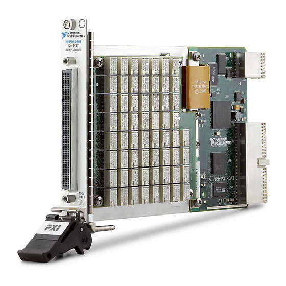
Advertisement

Related Manuals for NI PXI-2569


Summary of Contents for NI PXI-2569
- Page 1 PXI-2569 Features 2024-03-27...
- Page 2 PXI-2569 Overview........
- Page 3 PXI-2569 Features PXI-2569 Overview PXI-2569 Pinout 50-DPST Topology COM0W0 CH1W0 CH0W0 COM1W0 COM0W1 CH1W1 CH0W1 COM1W1 COM2W0 CH3W0 CH2W0 COM3W0 COM2W1 CH3W1 CH2W1 COM3W1 CH5W0 COM4W0 CH4W0 COM5W0 COM4W1 CH5W1 CH4W1 COM5W1 COM6W0 CH7W0 CH6W0 COM7W0 COM6W1 CH7W1 CH6W1 COM7W1...
- Page 4 PXI-2569 Features Table 1. Signal Descriptions Signal Description CHxW0 Wire 0 signal connection CHxW1 Wire 1 signal connection COMxW0 Routing destination for Wire 0 on the corresponding channel COMxW1 Routing destination for Wire 1 on the corresponding channel 100-SPST Topology...
- Page 5 PXI-2569 Features COM1 COM3 COM5 COM7 COM9 CH11 COM11 CH13 COM13 CH15 COM15 CH17 COM17 CH19 COM19 CH21 COM21 CH23 COM23 CH25 COM25 CH27 COM27 CH29 COM29 CH31 COM31 CH33 COM33 CH35 COM35 CH37 COM37 CH39 COM39 CH41 COM41 CH43...
- Page 6 PXI-2569 Features Table 2. Signal Descriptions Signal Description Signal connection COMx Routing destination for the corresponding channel PXI-2569 Hardware Diagram This figure shows the hardware diagram of the module. COM0 COM1 COM2 COM3 COM99 CH99 Topologies PXI-2569 50-DPST Topology Module software name: 2569/50-DPST (NISWITCH_TOPOLOGY_2569_50_DPST) The module is composed of 100 armature latching SPST relays.
- Page 7 CH2W0 is routed to COM2W0 ■ signal connected to CH2W1 is routed to COM2W1 ■ PXI-2569 100-SPST Topology Module software name: 2569/100-SPST (NISWITCH_TOPOLOGY_2569_100_SPST) The module is composed of 100 armature latching SPST relays. © National Instruments...
- Page 8 When scanning the module, a typical scan list entry could be ch2->com2;. This entry closes the relay between CH2 and COM2. PXI-2569 Relay Replacement The module uses electromechanical armature relays. Refer to the following table for information about ordering replacement relays.
- Page 9 Isopropyl alcohol ■ Cotton swabs ■ Note NI recommends using lead-free solder for relay replacement on lead-free assemblies, and lead solder for relay replacement on lead assemblies. Notice Do not rework lead assemblies using a lead-free work station. Lead solder from the unit could contaminate the station.
- Page 10 PXI-2569 Features Complete the following sets of steps to disassemble your module and replace a failed relay. 1. Ground yourself using a grounding strap or a ground connected to your PXI chassis. Note Properly grounding yourself prevents damage to your module from electrostatic discharge.
- Page 11 PXI-2569 Features Figure 2. Mezzanine Board K75 K83 K91 K99 K46 K53 K60 K67 K74 K82 K90 K98 K45 K52 K59 K66 K73 K81 K89 K97 K44 K51 K58 K65 K72 K80 K88 K96 K43 K50 K57 K64 K71 K79 K87 K95...
- Page 12 PXI-2569 Features Channel Relay Channel Relay Channel Relay Channel Relay Name Name Name Name Name Name Name Name CH19 CH44 CH69 CH94 CH20 CH45 CH70 CH95 CH21 CH46 CH71 CH96 CH22 CH47 CH72 CH97 CH23 CH48 CH73 CH98 CH24 CH49...
- Page 13 PXI-2569 Features a. Screws b. Washers c. Lead Covers (If Present) d. Hex Standoff e. Base Board 4. Separate the mezzanine board from the base board. 5. Locate the assembly and serial number labels on the board with the relay you want to replace.
- Page 14 Do not use flux remover to clean the board after relay replacement. Use the NI-SWITCH Switch Soft Front Panel to reset the relay count after you have replaced a failed relay. Refer to the Switch Soft Front Panel Help for more information.
Need help?
Do you have a question about the PXI-2569 and is the answer not in the manual?
Questions and answers