Table of Contents
Advertisement
Quick Links
Advertisement
Table of Contents

Related Manuals for NI PXIe-5654


Summary of Contents for NI PXIe-5654
- Page 1 PXIe-5654 2024-03-26...
-
Page 2: Table Of Contents
Direct Connections to the NI 5654........ -
Page 3: Ni 5654 Rf Signal Generator
This document explains how to install, configure, and test the NI PXIe-5654 (NI 5654) as a stand-alone device. The NI 5654 is a 10 GHz or 20 GHz continuous-wave RF signal generator. The NI 5654 ships with the NI-RFSG instrument driver, which you use to program the device. -
Page 4: Verifying The System Requirements
3 m (10 ft). Verifying the System Requirements To use the NI-RFSG instrument driver, your system must meet certain requirements. Refer to the product readme, which is available on the driver software media or online at ni.com/manuals, for more information about minimum system... -
Page 5: Verifying The Kit Contents
PXIe-5654 Caution Never touch the exposed pins of connectors. Notify NI if the device appears damaged in any way. Do not install a damaged device. 3. Unpack any other items and documentation from the kit. Store the device in the antistatic package when the device is not in use. -
Page 6: Preparing The Environment
The NI PXIe-5696 amplitude extender (AE) module (NI part number ■ 783128-01). Preparing the Environment Ensure that the environment you are using the NI 5654 in meets the following specifications. Operating ambient temperature 0 °C to 55 °C (IEC 60068-2-1, IEC 60068-2-2) -
Page 7: Installing The Software
If the installation window does not appear, navigate to the drive, double-click it, and double-click autorun.exe. 3. Follow the instructions in the installation prompts to install the NI-RFSG driver software. Note Windows users may see access and security messages during installation. -
Page 8: Installing The Sma Cables
PXIe-5654 Figure 2. Chassis Compatibility Symbols NI PXIe-1062Q a. PXI Express System Controller Slot b. PXI Peripheral Slot c. PXI Express Hybrid Peripheral Slot d. PXI Express System Timing Slot e. PXI Express Peripheral Slot 6. Touch any metal part of the chassis to discharge static electricity. -
Page 9: Direct Connections To The Ni 5654
PXIe-5654 To use the NI 5654 with other devices, such as the NI 5696 AE, you must make connections using SMA cables. For best results when connecting signals to the NI 5654 front panel SMA connectors, use shielded low-loss coaxial cables. -
Page 10: Ni 5654 Rf Signal Generator Module
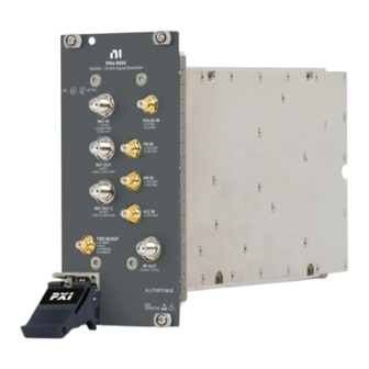
PXIe-5654 The NI 5654 is a precision RF instrument that is sensitive to ESD and transients. Ensure you take the following precautions when making direct connections to the NI 5654 to avoid damaging the device. Note Do not apply external signals to the NI 5654. Applying external signals may cause damage. - Page 11 PXIe-5654 Figure 3. NI 5654 RF Signal Generator Module Front Panel 250 kHz–20 GHz Signal Generator ACCESS ACTIVE PULSE REF IN 1–20 MHz –0.5V MIN ±10 dBm NOM +5.5V MAX 17 dBm MAX FM IN REF OUT 10 MHz ±1 VDC NOM ±2 VDC MAX...
- Page 12 PXIe-5654 Table 2. NI 5654 Front Panel Connectors Connector REF IN Input terminal that routes an external reference signal to the NI 5654. REF OUT Output terminal that can route a 10 MHz reference signal from the NI 5654. REF OUT 2 Output terminal that can route a 100 MHz reference signal from the NI 5654.
-
Page 13: Configuring The Ni 5654 In Max
RED—The module has detected an error state; this may indicate a PLL lock failure or a thermal shutdown condition. Configuring the NI 5654 in MAX Use Measurement & Automation Explorer (MAX) to configure your National Instruments hardware. MAX informs other programs about which devices reside in the system and how they are configured. -
Page 14: Programming The Ni 5654
Programming the NI 5654 You can generate signals interactively using the NI-RFSG Soft Front Panel (SFP), or you can use the NI-RFSG instrument driver to program your device in the supported ADE of your choice. Table 4. NI 5654 Programming Options... -
Page 15: Ni-Rfsg Examples
Hardware Input and Output » Modular Instruments. Generating a Signal Using the NI-RFSG Soft Front Panel To verify your device configuration, use the NI-RFSG Soft Front Panel (SFP) in MAX to generate a simple signal. 1. Within MAX, select the NI 5654 RF signal generator module in the configuration tree. -
Page 16: Building A Basic Ni-Rfsg Application
You can use the Search button on the Functions palette to find the NI-RFSG palette. 6. Add the core NI-RFSG VIs from the NI-RFSG palette to the block diagram, and wire the VIs together as shown in the following figure. -
Page 17: Adding A While Loop
11. In the VI front panel power level (dBm) control, enter 0. In the frequency (Hz) control, enter 100M (100 MHz). 12. In the VI front panel resource name control, enter the NI 5654 device name that you specified in MAX. - Page 18 PXIe-5654 Figure 6. The niRFSG Check Generation Status VI Enclosed in the While Loop 3. Right-click the While Loop tunnels, and select Replace with Shift Register. 4. Select the Or function on the Boolean palette. Place the function inside the While Loop.
-
Page 19: Adding An Error Indicator
PXIe-5654 Figure 7. While Loop with Stop Button Adding an Error Indicator Add an error indicator to the VI front panel. 1. Create an error indicator by right-clicking the error out output of the niRFSG Close VI and selecting Create » Indicator. -
Page 20: Troubleshooting
PXIe-5654 Figure 9. Basic Sine Wave Generation VI Front Panel 3. Open the VI front panel, and select the NI 5654 module name specified in MAX in the resource name control. 4. Click the Run button on the toolbar to initiate sine wave generation. -
Page 21: What Should I Do If The Ni 5654 Doesn't Appear In Max
6. Verify that the device appears in MAX. 7. Reset the device in MAX and perform a self-test. What Should I Do if the NI 5654 Doesn't Appear in MAX? 1. In the MAX configuration tree, click Devices and Interfaces. -
Page 22: What Should I Do If The Module Fails The Self-Test
5. If you are using a PXI controller, verify that a National Instruments entry appears in the system device list. Reinstall NI-RFSG and the device if error conditions appear in the list. If you are using an MXI controller, right-click PCI- to-PCI Bridge, and select Properties from the shortcut menu to verify that the bridge is enabled. -
Page 23: Worldwide Support And Services
PXIe-5654 The NI RF Signal Generators Help is an HTML version of a traditional user manual that includes detailed information about RF fundamentals, device features, and programming with NI-RFSG. Worldwide Support and Services The National Instruments website is your complete resource for technical support.
Need help?
Do you have a question about the PXIe-5654 and is the answer not in the manual?
Questions and answers