Table of Contents
Advertisement
Quick Links
Advertisement
Table of Contents

Subscribe to Our Youtube Channel
Related Manuals for NI PXI-4110


Summary of Contents for NI PXI-4110
- Page 1 PXI-4110 User Manual 2024-03-26...
-
Page 2: Table Of Contents
Installing the Optional Auxiliary 12 V Power Source on the PXI-4110....24 Installing the Output Connector on the PXI-4110....... 26 Verifying the Installation in MAX. - Page 3 Cleaning the PXI-4110 System........
-
Page 4: Welcome To The Pxi-4110 User Manual
PXI-4110 User Manual Welcome to the PXI-4110 User Manual The PXI-4110 User Manual provides detailed descriptions of product functionality and step-by-step processes for use. Looking for something else? For information not found in the User Manual for your product, like specifications or API reference, browse Related Information. -
Page 5: Pxi-4110 Overview
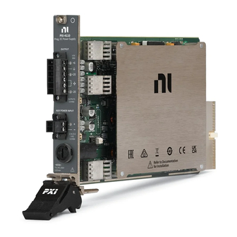
PXI-4110 User Manual PXI-4110 Overview The PXI-4110 is a triple-output, single-quadrant, programmable power supply in a single-slot, 3U PXI module. It is designed for engineers performing design validation and manufacturing test applications. Use the PXI-4110 for constant voltage (CV) applications or PXI-4110 constant current (CC) operation with programmable setpoint levels and limits. - Page 6 -20 V +6 V +20 V Quadrant III Quadrant IV Source Sink Driver Support NI recommends that you use the newest version of the driver for your module. Table 1. Earliest Driver Version Support Driver Name Earliest Version Support NI-DCPower ni.com...
-
Page 7: Components Of A Pxi-4110 System
PXI-4110 User Manual Components of a PXI-4110 System The PXI-4110 is designed for use in a system that includes other hardware components, drivers, and software. Notice A system and the surrounding environment must meet the requirements defined in PXI-4110 Specifications. - Page 8 Cables and Accessories for recommended cables and accessories and guidance. NI-DCPower Driver Instrument driver software that provides functions to interact with the PXI-4110 and execute measurements using the PXI-4110. Note NI recommends always using the most current version of NI- DCPower with the PXI-4110.
- Page 9 C/C++ ■ .NET ■ Python ■ Cables and Accessories NI recommends using the following cables and accessories with your module. Table 3. Cables and Accessories Accessory Description Notes Part Number APS-4100, an optional auxiliary The PXI-4110 is available in kits...
- Page 10 Programming Options You can generate signals interactively using InstrumentStudio or you can use the NI-DCPower instrument driver to program your device in the supported ADE of your choice. • InstrumentStudio—When you install NI-DCPower on a 64-bit system, you can monitor, control, and record measurements from supported devices using InstrumentStudio.
- Page 11 ■ Creating an Application with NI-DCPower in Microsoft Visual C and C++ topic of the NI DC Power Supplies and SMUs Help to manually add all required include and library files to your project. NI-DCPower does not ship with installed C/C++ examples.
-
Page 12: Pxi-4110 Theory Of Operation
SAR ADCs with a fixed measurement aperture. Measurements are performed on- demand and are not synchronized with each other. The bank-isolated outputs (channels 1 and 2) on the PXI-4110 can operate from the PXI chassis power (internal power) or from an auxiliary DC power supply. The non- isolated output (channel 0) always operates from the PXI chassis power (internal power). - Page 13 PXI-4110 User Manual Block Diagram The following diagram illustrates the design of the PXI-4110. Figure 2. PXI-4110 Block Diagram Channel 0 +5 V Power Boost Management Converter Power Stage Shunt User Replacable Voltage Setpoint 33 μF Current Setpoint 60 V CAT I Isolation...
-
Page 14: Pxi-4110 Front Panel
PXI-4110 User Manual PXI-4110 Front Panel Figure 3. PXI-4110 Front Panel PXI-4110 Programmable DC Power Supply OUTPUT OUTPUTS 1A MAX AUX POWER INPUT 11-15.5 5A MAX T 6,3A L 250V 5-20 mm 1. Output Connector 2. Auxiliary Power Input Connector 3. - Page 15 PXI-4110 User Manual 4. Output Channel LEDs 5. Auxiliary Power Input LED © National Instruments...
-
Page 16: Pxi-4110 Pinout
PXI-4110 User Manual PXI-4110 Pinout The following figures show the terminals on the PXI-4110 output connector and auxiliary power input connector. Output Connector Figure 4. PXI-4110 Output Connector Pinout CH 0 CH 1 Isolated GND Isolated GND CH 2 –20 Table 4. - Page 17 (generates and/or dissipates power). Positive polarity is defined as voltage measured on HI > LO. Auxiliary Power Input Connector Figure 5. PXI-4110 Auxiliary Power Input Connector Pinout Terminal 0 + Terminal 1 – Table 5. Auxiliary Power Input Signal Descriptions...
-
Page 18: Pxi-4110 Led Indicators
PXI-4110 User Manual PXI-4110 LED Indicators The PXI-4110 features Output Channel LEDs and an Auxiliary Power Input LED. Output Channel LEDs The Output Channel LEDs, located on the module front panel, indicates the output channel state. The following table lists the Output Channel LED states. - Page 19 PXI-4110 User Manual Note A green Auxiliary Power Input status indicator does not indicate that the auxiliary power is in use. To determine if the PXI-4110 is using auxiliary power, use the niDCPower Source In Use property or the NIDCPOWER_ATTR_POWER_SOURCE_IN_USE attribute.
-
Page 20: Pxi-4110 Installation And Configuration
PXI-4110 User Manual PXI-4110 Installation and Configuration Complete the following steps to install the PXI-4110 into a chassis and prepare it for use. Unpacking the Kit Installing the Software Installing the PXI-4110 into a Chassis Installing the Optional Auxiliary 12 V Power Source on the PXI-4110... -
Page 21: Installing The Software
PXI-4110 User Manual Kit Contents Refer to the following figure to identify the contents of the PXI-4110 kit. Figure 6. PXI-4110 Kit Contents 1. PXI-4110 Module 2. 6-position MINI-COMBICON connector 3. 2-position MINI-COMBICON connector 4. Backshell for 6-position MINI-COMBICON connector 5. -
Page 22: Installing The Pxi-4110 Into A Chassis
4. Remove the black plastic covers from all the captive screws on the module front panel. 5. Identify a supported slot in the chassis. You can place the PXI-4110 module in PXI peripheral slots ( )or PXI Express hybrid peripheral slots ( 6. - Page 23 PXI-4110 User Manual 7. Ensure that the ejector handle is in the unlatched (downward) position. 8. Place the module edges into the module guides at the top and bottom of the chassis. Slide the module into the slot until it is fully inserted.
-
Page 24: Installing The Optional Auxiliary 12 V Power Source On The Pxi-4110
Installing an auxiliary 12 V power source is an optional step that allows you to gain full output power of the isolated channels on the PXI-4110. Compatible auxiliary 12 V power sources must be capable of providing 11 V to 15.5 V and ≥60 W to increase the output current capability of channels 1 and 2 to 1 A. - Page 25 In case of auxiliary power loss during operation, the isolated output is disabled, and the power supply is shut down to prevent damage to the PXI-4110 and the load. If auxiliary power loss occurs, complete the following steps to resume operation: 1.
-
Page 26: Installing The Output Connector On The Pxi-4110
3. Connect the 6-position assembled connector to the device. Note Using the provided backshell for the output connector provides protection against accidental shorts to output terminals and strain relief. 4. Screw in the flange to lock the connector to the PXI-4110. 5. Power on the chassis. ni.com... - Page 27 You can cascade multiple channels in series to generate greater output voltage because channels 1 and 2 on the PXI-4110 are bank-isolated outputs with a shared terminal, which is a series arrangement. The isolation rating of the channel 1 + 2 bank is 60 V, which allows it to be floated on top of the output of channel 0 for up to 46 V at 1 A as illustrated in the following figure.
- Page 28 PXI-4110 User Manual 3. Load Connecting Multiple Channels in Parallel You can connect identical channels from multiple PXI-4110 modules in parallel to generate greater output current. Caution Do not exceed 60 V DC from any terminal to ground when cascading power supplies.
-
Page 29: Verifying The Installation In Max
Verifying the Installation in MAX Use Measurement & Automation Explorer (MAX) to configure your NI hardware. MAX informs other programs about which NI hardware products are in the system and how they are configured. MAX is automatically installed with NI-DCPower . - Page 30 5. Self-test the hardware by selecting the item in the configuration tree and clicking Self-Test in the MAX toolbar. MAX self-test performs a basic verification of hardware resources. What Should I Do if the PXI-4110 Does Not Appear in MAX? 1. In the MAX configuration tree, expand Devices and Interfaces.
- Page 31 If error conditions appear, reinstall the NI-DCPower driver. What Should I Do if the PXI-4110 Fails the Self-Test? 1. Reset the PXI-4110 through MAX, and then perform the self-test again. 2. Restart the system, and then perform the self-test again.
-
Page 32: Connecting Signals To The Pxi-4110
2 Output LO When the PXI-4110 is operating in Constant Voltage mode, local sense forces the requested voltage at the output terminals of the module. The actual voltage at the DUT terminals is lower than the requested output because of the output lead resistance error. -
Page 33: Minimizing Voltage Drop Loss When Cabling
To minimize voltage drop caused by cabling: Keep each wire pair as short as possible ■ Use the thickest wire gauge appropriate for your application. NI ■ recommends 18 AWG or lower. To reduce noise picked up by the cables that connect the SMU to a load, twist each wire pair. - Page 34 PXI-4110 User Manual Calculating Voltage Drop When cabling a power supply or SMU to a constant load, be sure to account for voltage drop in your application. If necessary, adjust the output voltage of the device. Use the amount of current flowing through the cabling wires and the resistance of...
-
Page 35: Source Mode
PXI-4110 User Manual Source Mode The PXI-4110 channels can generate voltage and current in Single Point source mode. Within Single Point source mode, you can output the following: DC voltage ■ DC current ■ The Source Mode With Channels function defines the source mode the PXI-4110 channels are operating in. -
Page 36: Sourcing Voltage And Current
Depending on the output function and source mode, you can configure the appropriate output levels and limits. Configure the PXI-4110 for Measuring Once you configure channels and they are in the Running state, the PXI-4110 can take measurements. Configure Events You can use events to coordinate the operation of multiple channels and instruments. -
Page 37: Configure The Pxi-4110 For Sourcing
Configure the PXI-4110 for Sourcing Use the NI-DCPower driver with the PXI-4110 to control the output the instrument generates. Depending on the output function and source mode, you can configure the appropriate output levels and limits. -
Page 38: Configure The Pxi-4110 For Measuring
For example, among other aspects, you can specify output ranges. Configure the PXI-4110 for Measuring Once you configure channels and they are in the Running state, the PXI-4110 can take measurements. Use the niDCPower Measure property or the NIDCPOWER_ATTR_MEASURE_WHEN attribute to configure how NI-DCPower takes measurements. -
Page 39: Configure Events
With Channels VI or the niDCPower_WaitForEventWithChannels function. NI-DCPower Synchronization Methods Synchronization allows you to coordinate the action of multiple NI instruments. There are multiple approaches to synchronizing NI instruments; the accuracy (trigger delay and jitter) of the synchronization depends on the approach you take and the system and instruments in use. -
Page 40: Initiate The Pxi-4110 For Sourcing And Measuring
Accuracy: tens of milliseconds Initiate the PXI-4110 for Sourcing and Measuring Initiate the channels of the PXI-4110 to apply a configuration and start generating. Use the niDCPower Initiate With Channels VI or the niDCPower_InitiateWithChannels function to apply the configuration and start generating voltage or current. -
Page 41: Close The Session
However, you can programmatically enable and disable the output channel(s) of the PXI-4110. When you disable the output of the PXI-4110, the instrument is configured to output a DC voltage at 0 V with current limits at ±2% of the presently configured current limit range in, unless otherwise noted, a low-impedance state. - Page 42 When debugging your application, it is common to abort execution before you close. While aborting the execution should not cause problems, NI does not recommend doing When you close a session, the channels continue to operate in their last configured state.
-
Page 43: Example Programs
NI Example Finder The NI Example Finder is a utility that organizes examples into categories and allows you to browse and search installed examples. For example, search for "DCPower" to locate all NI-DCPower examples. You can see descriptions and compatible hardware models for each example or see all the examples compatible with one particular hardware model. - Page 44 DCPower\Examples\DotNET 4.5 Common Example Programs The following NI-DCPower example programs demonstrate common SMU and power supply functions and operations. • NI-DCPower Source DC Voltage—Demonstrates how to force an output voltage. • NI-DCPower Source DC Current—Demonstrates how to force an output current.
-
Page 45: Pxi-4110 Operating Guidelines
The terms sourcing and sinking describe power flow into and out of a device, respectively. The PXI-4110 is capable of only sourcing power and not sinking power. Devices that are sourcing power are delivering power into a load, while devices that are sinking power behave like a load, absorbing power that is being driven into them and providing a return path for current. -
Page 46: Output Impedance
Quadrant I or Quadrant III, individually, each channel on the PXI-4110 can operate only within one quadrant (channels 0 and 1 operate only within Quadrant I, and channel 2 operates only within Quadrant III). Thus, all channels on the PXI-4110 are single-quadrant supplies. - Page 47 PXI-4110 User Manual output voltage. The slew rate of the instrument to a new setpoint will be limited by output capacitance in constant current mode. In constant voltage mode, the controller forces the output voltage to match the setpoint, even when there is a voltage drop across the resistor. The slew rate of the instrument to a new setpoint will be limited by output inductance in constant voltage mode.
- Page 48 Virtual output capacitance can significantly limit output slew rate. For example, consider the PXI-4110 stepping from 1 V to 2 V in the 1 A range with a 20 mA compliance limit. Even in the absence of a load, the 20 mA compliance current charging the virtual capacitance limits the output slew rate.
-
Page 49: Protection
PXI-4110 and the load. When its fuse is blown, an output channel can source only a few milliamperes of current regardless of the programmed current limit. -
Page 50: Load Regulation
Auxiliary Power Input Protection The auxiliary power input of the PXI-4110 can accept voltages from 11 V to 15.5 V. Applying a voltage below 11 V or above 15.5 V disables the auxiliary power input. - Page 51 PXI-4110 User Manual Inductive Loads In constant voltage mode, most inductive loads remain stable. However, when operating in constant current mode in higher current ranges, increasing output capacitance may help improve stability. Capacitive Loads Generally, a power supply or SMU remains stable when driving a capacitive load.
- Page 52 PXI-4110 User Manual Figure 12. Transient Response Transient Response Time ∆ V Transient Voltage Dip ∆I There is a trade-off between transient response and the stability of the supply under a wide variety of loads. To achieve the fastest transient response, an instrument should have a high gain-bandwidth (GBW) product, but the higher GBW is, the more likely it is that the instrument will become unstable with certain loads.
-
Page 53: Ranges
Ranges NI power supplies and SMUs use one or more ranges for voltage and current output, as well as one or more ranges for voltage and current measurement. - Page 54 When you configure an output range, if you request a range that differs from the ranges described in the PXI-4110 Specifications, NI-DCPower selects the highest resolution (smallest) range available that accommodates the requested range. For example, if you request 100 mA current range on a device with only 20 mA and 200 mA current limit ranges, NI-DCPower selects the 200 mA range.
- Page 55 If the current range is changed while the PXI-4110 is in constant current mode, a spike in the output current could occur for a maximum of 3 ms. This will not occur if the PXI-4110 is in constant voltage mode. Source Autoranging When you enable source autorange by setting Source »...
-
Page 56: Noise
PXI-4110 User Manual setpoint. NI-DCPower automatically changes to the highest resolution (smallest) range that can accommodate the configured output value. You can selectively enable source voltage level/limit and current limit/level autorange on a channel. Note While source autorange selects the best range based on the setpoint, it does not change the range until you program a new setpoint. - Page 57 Rejecting AC Noise in DC Measurements with Measurement Averaging The PXI-4110 allows you to adjust the number of samples averaged in each measurement to influence the aperture time of your measurements, which allows you to reject specific AC noise frequencies. You can set the number of samples to average programmatically using the niDCPower Samples To Average property or the NIDCPOWER_ATTR_SAMPLES_TO_AVERAGE attribute.
- Page 58 Measure Multiple in your program. You can set Reset Average Before Measurement to False after Measure Multiple runs. Determining Measurement Rate Although the measurement speed of the PXI-4110 is 3 kS/s for all voltage and current measurements, the measurement rate of the PXI-4110 can vary depending ni.com...
- Page 59 10 samples second If no measurement averaging is used (Samples To Average = 1), the PXI-4110 returns 3,000 measurements per second. While measuring without averaging yields the fastest measurement rate, noise from the environment (for example, the 50 Hz or 60 Hz noise introduced by cabling) increases measurement uncertainty.
-
Page 60: Resistance Measurements
To measure a resistance with an NI power supply or SMU, select a test current that creates a voltage drop within module capabilities. After the channel output is... -
Page 61: Replacing A Fuse
For example, if your first current is 1 A, you could choose a second test current of 10 mA. Replacing a Fuse All of the input and output connections on the PXI-4110 front panel have user- replaceable fuses. If you suspect a blown output channel fuse, remember that an output channel with a blown fuse can source only a few milliamperes of current, regardless of the programmed current limit. - Page 62 3. Output Channel Fuse (Channel 1) 4. Auxiliary Input Fuse 5. Spare Output Channel Fuse To replace a fuse on the PXI-4110, complete the following steps: 1. Power down the chassis. 2. Disconnect all output and auxiliary power connections. 3. Remove the PXI-4110 from the chassis.
-
Page 63: Sourcing And Measuring Terminology
Screw the cap clockwise to replace it on the PXI-4110 front panel. Note You can use the spare fuse included on the PXI-4110 to replace an output channel fuse. Sourcing and Measuring Terminology Refer to the following terms when learning more about the features and usage of the PXI-4110: •... - Page 64 For NI DC power supplies and SMUs, the line regulation specification only applies to devices with an auxiliary power input. • Load Regulation—A measure of the ability of an output channel to remain constant given changes in the load.
-
Page 65: Calibration
Self-heating from surrounding equipment, uncontrolled manufacturing floor environment, and dirty fan filters are among these factors. Refer to the PXI-4110 Specifications for the following information for your instrument: Recommended operating temperature range ■... - Page 66 Refer to the PXI-4110 Calibration Procedure for the external calibration procedure for your instrument. Accuracy A measurement or output level on a power supply can differ from the actual or requested value.
- Page 67 These two error terms are added to determine the total accuracy specification for a given measurement. NI power supplies typically specify offset errors with absolute units (for example, mV or μA), while gain errors are specified as a percentage of the reading or the requested value.
-
Page 68: Cleaning The Pxi-4110 System
PXI-4110 User Manual Cleaning the PXI-4110 System NI recommends the following to clean and maintain your instrument's system: Clean the fan filters on the chassis regularly to prevent fan blockage and to ■ ensure efficient air circulation. Cleaning frequency depends on the amount of use and the operating environment.
Need help?
Do you have a question about the PXI-4110 and is the answer not in the manual?
Questions and answers