Advertisement
Quick Links
Advertisement

Subscribe to Our Youtube Channel
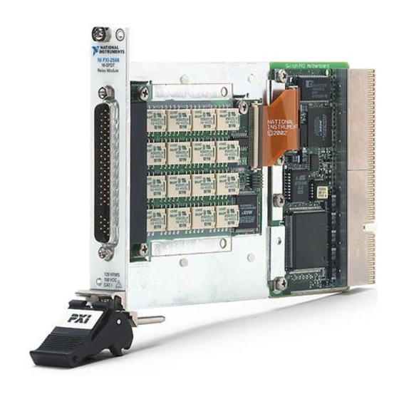
Summary of Contents for NI PXI-2566
- Page 1 PXI-2566 Features 2024-03-28...
- Page 2 PXI-2566 Overview........
- Page 3 PXI-2566 Features PXI-2566 Overview PXI-2566 Pinout 8-DPDT Topology COM0W0 NO0W0 NC0W0 COM0W1 NO0W1 NC0W1 COM1W0 NO1W0 NC1W0 COM1W1 NO1W1 NC1W1 COM2W0 NO2W0 NC2W0 COM2W1 NO2W1 NC2W1 COM3W0 NO3W0 NC3W0 COM3W1 NO3W1 NC3W1 COM4W0 NO4W0 NC4W0 COM4W1 NO4W1 NC4W1 COM5W0 NO5W0...
- Page 4 PXI-2566 Features Signal Description NCxW1 Wire 1 for normally closed signal connection NOxW0 Wire 0 for normally open signal connection NOxW1 Wire 1 for normally open signal connection RSVD Reserved, do not connect TRIG IN Trigger input connection TRIG OUT...
- Page 5 TRIG OUT Trigger output connection Notice Do not connect to RESERVED pins. Keep low-voltage pins isolated from row and column channels when high voltage is present. PXI-2566 Hardware Diagram This figure shows the hardware diagram of the module. COM0 COM8 COM1...
- Page 6 PXI-2566 Features Topologies PXI-2566 8-DPDT Topology Module software name: 2566/8-DPDT (NISWITCH_TOPOLOGY_2566_8_DPDT) Note Switching inductive loads (for example, motors and solenoids) can produce high voltage transients in excess of the module's rated voltage. Without additional protection, these transients can interfere with module operation and impact relay life.
- Page 7 PXI-2566 Features com0 com1 com2 com7 Making a Connection You can control the channels using the niSwitch Connect Channels VI or the niSwitch_Connect function. To connect the NO terminal to the COM terminal of that channel, disconnect the NC terminal from the COM of that channel.
- Page 8 "nc2", "com2") When scanning the module, a typical scan list entry could be nc2->com2;. This entry routes the signal connected to NC2 to COM2. PXI-2566 16-SPDT Topology Module software name: 2566/16-SPDT (NISWITCH_TOPOLOGY_2566_16_SPDT) Note Switching inductive loads (for example, motors and solenoids) can produce high voltage transients in excess of the module's rated voltage.
- Page 9 PXI-2566 Features com0 com1 com2 nc15 com15 no15 Making a Connection You can control the channels using the niSwitch Connect Channels VI or the niSwitch_Connect function. To connect the NO terminal to the COM terminal of that channel, disconnect the NC terminal from the COM of that channel.
- Page 10 When scanning the module, a typical scan list entry could be nc2->com2;. This entry routes the signal connected to NC2 to COM2. PXI-2566 Relay Replacement The module uses electromechanical armature relays. Refer to the following table for information about ordering replacement relays.
- Page 11 Isopropyl alcohol ■ Cotton swabs ■ Note NI recommends using lead-free solder for relay replacement on lead-free assemblies, and lead solder for relay replacement on lead assemblies. Notice Do not rework lead assemblies using a lead-free work station. Lead solder from the unit could contaminate the station.
- Page 12 PXI-2566 Features Note Older versions of this module might have adhesive plastic lead covers that you must remove. The module retains full specifications even if the covers are not reinstalled. 3. Locate the assembly and serial number labels on the board with the relay you want to replace.
- Page 13 Do not use flux remover to clean the board after relay replacement. Use the NI-SWITCH Switch Soft Front Panel to reset the relay count after you have replaced a failed relay. Refer to the Switch Soft Front Panel Help for more information.


Need help?
Do you have a question about the PXI-2566 and is the answer not in the manual?
Questions and answers