Table of Contents
Advertisement
Quick Links
Advertisement
Table of Contents

Subscribe to Our Youtube Channel
Related Manuals for NI PXIe-5820


Summary of Contents for NI PXIe-5820
- Page 1 PXIe-5820 Getting Started 2024-03-25...
-
Page 2: Table Of Contents
Direct Connections to the PXIe-5820........ -
Page 3: Pxie-5820 Getting Started Guide
Before you begin, install and configure your chassis and controller. This document explains how to install, configure, and test the PXIe-5820. The PXIe-5820 is a baseband I/Q vector signal transceiver (VST) and ships with the NI- RFSA and NI-RFSG driver software, which you use to program the device. -
Page 4: Verifying The System Requirements
3 meters in length. Verifying the System Requirements To use the PXIe-5820, your system must meet certain requirements. For more information about minimum system requirements, recommended system, and supported application development environments (ADEs), refer to the readme, which is installed or available at ni.com/manuals. -
Page 5: Preparing The Environment
PXIe-5820 Getting Started Preparing the Environment Ensure that the environment you are using the PXIe-5820 in meets the following specifications. Operating ambient temperature 0 °C to 45 °C Operating relative humidity 10% to 90%, noncondensing (IEC 60068-2-56) Maximum altitude 2,000 m (800 mbar) (at 25 °C ambient... -
Page 6: Other Equipment
PXIe-5820 Getting Started Other Equipment There are several required items not included in your device kit that you need to operate the PXIe-5820. Your application may require additional items not included in your kit to install or operate your device. Required Items ■... -
Page 7: Installing The Software
FPGA using signals to test receivers. precompiled bitfiles. Related information: Refer to the NI RF Vector Signal Analyzers Help or the NI RF Signal ■ Generators Help for more information about using the NI-RFSA and NI-RFSG instrument driver FPGA extensions. -
Page 8: Installing The Pxie-5820
This document is also available at ni.com/manuals. The PXIe-5820 is a two-slot module with two backplane connectors. The module must be installed into two adjacent chassis slots. 1. Ensure the AC power source is connected to the chassis before installing the module. - Page 9 PXI Express System Timing Slot e. PXI Express Peripheral Slot The PXIe-5820 can be placed in PXI Express peripheral slots, PXI Express Hybrid peripheral slots, or PXI Express system timing slots. 8. Touch any metal part of the chassis to discharge static electricity.
-
Page 10: Direct Connections To The Pxie-5820
14. Power on the chassis. Direct Connections to the PXIe-5820 The PXIe-5820 is a precision instrument that is sensitive to ESD and transients. Ensure you take the following precautions when making direct connections to the PXIe-5820 to avoid damaging the device. -
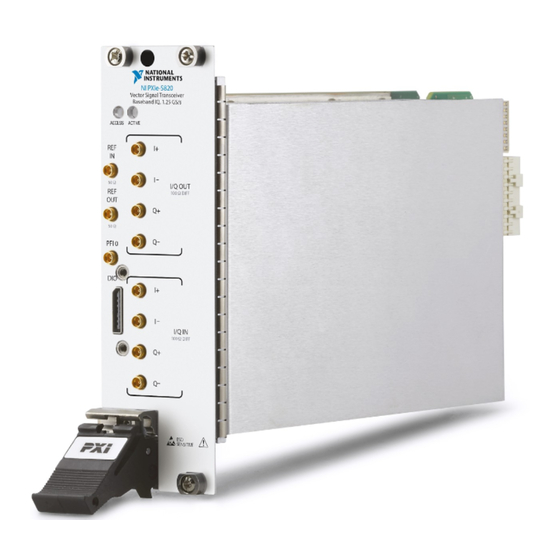
Page 11: Hardware Front Panel Connectors And Indicators
DIFF Q– SENSITIVE Caution Apply external signals only while the PXIe-5820 is powered on. Applying external signals while the device is powered off may cause damage. Table 2. Device Front Panel Icon Definitions Refer to the user documentation for required... - Page 12 LVCMOS signals. Caution The DIO connector is not an OCuLink interface. Do not connect the DIO connector on the PXIe-5820 to the OCuLink interface of another device. NI is not liable for any damage resulting from such signal connections. Table 4. I/Q Connector Descriptions...
- Page 13 PXIe-5820 Getting Started Connector Description Connector Type Output connector for MMPX (f) Q- signals. I/Q IN Input connector for I+ MMPX (f) signals. Input connector for I- MMPX (f) signals. Input connector for Q+ MMPX (f) signals. Input connector for Q- MMPX (f) signals.
-
Page 14: Configuring The Hardware In Max
NI hardware. MAX lists all installed modules under the name of their associated chassis. 3. Expand your Chassis tree item. PXIe-5820 devices appear as NI-RIO modules in the list. The default names of your device may vary. Note If your module is not listed, refer to the Troubleshooting section of this document. -
Page 15: Self-Calibration
Self-calibration adjusts the PXIe-5820 for variations in the module environment using an onboard high-precision calibration tone. PXIe-5820 modules are externally calibrated at the factory; however, you should perform a self-calibration in any of the following situations: After first installing the PXIe-5820 into your chassis ■... -
Page 16: Software Locations
RFSA » Utilities » RFSA Self Calibration. b. Open the example. 3. Complete the following steps to configure the example: a. Select the device identifier assigned to the PXIe-5820 in MAX in the [Resource Name] drop-down menu . b. Set Clock Source to OnboardClock. - Page 17 PXIe-5820 Getting Started Software Option Location Windows 10 (64- ■ bit)/8.1 (64-bit)/7 (64-bit)- Program Files (x86)\IVI Foundation\IVI Microsoft Visual C/C++ Use the header files located in the <IVIROOTDIR32>\Include directory and import library files located in the <IVIROOTDIR32>\Lib directory, where <IVIROOTDIR32> is one...
-
Page 18: Using The Ni Example Finder
Info Code NETAPIdriversupport. Using the NI Example Finder If you're using NI-RFSA or NI-RFSG with LabVIEW or LabWindows/CVI, use the NI Example Finder to locate programming examples. 1. Launch LabVIEW or LabWindows/CVI. 2. Select Help » Find Examples to open the NI Example Finder. -
Page 19: Using Microsoft Visual C/C
PXIe-5820 Getting Started 4. Open the example that best matches your application requirements. Using Microsoft Visual C/C++ If you're using NI-RFSA with Microsoft Visual C/C++, locate examples in the following directory. Table 7. Location of Microsoft Visual C/C++ Programming Examples... -
Page 20: Troubleshooting
5. Start the NI-RFSG example to generate the CW tone at the I/Q OUT connectors of the device. 6. Start the NI-RFSA example to acquire the CW tone at the I/Q IN connectors of the device. Troubleshooting... -
Page 21: Why Is The Access Led Off When The Chassis Is On
PXIe-5820 Getting Started click the PXIe-5820 and NI-RIO FPGA Device nodes and select Update Driver. If you are using an MXI controller, right-click PCI-to-PCI Bridge, and select Properties from the shortcut menu to verify that the bridge is enabled. 6. Restart your computer.
Need help?
Do you have a question about the PXIe-5820 and is the answer not in the manual?
Questions and answers