Advertisement
Quick Links
Advertisement

Related Manuals for NI PXI-2503


Summary of Contents for NI PXI-2503
- Page 1 PXI-2503 Features 2024-03-28...
- Page 2 PXI-2503 Relay Replacement........
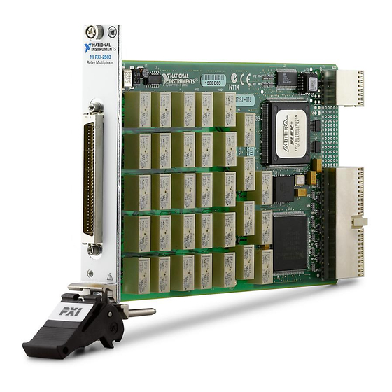
- Page 3 PXI-2503 Features PXI-2503 Overview PXI-2503 Hardware Diagram CH11+ CH11– CH10+ CH10– CH9+ CH9– Bank1 CH8+ CH8– CH7+ CH7– COM1+ CH6+ COM1– CH6– BC01 CH5+ CH5– CH4+ CH4– CH3+ CH3– Bank0 HLSELECT CH2+ CH2– AB0+ AB0– CH1+ CH1– 1WIRE COM0+ CH0+ COM0–...
- Page 4 4-wire 12x1 Multiplexer 2501/4-Wire 12x1 Mux (NISWITCH_TOPOLOGY_2501_4_WIRE_12X1_M 2-wire 4x6 Matrix 2501/2-Wire 4x6 Matrix (NISWITCH_TOPOLOGY_2501_2_WIRE_4X6_MA TRIX) 1-Wire 48 × 1 Multiplexer Topology Connect your signals using the NI TB-2605 terminal block. 1-Wire 48 × 1 Multiplexer – com0 – ch47 (1wireREF) ni.com...
- Page 5 PXI-2503 Features Making a connection In 1-wire mode, all channels can connect to COM0+. COM0– is always connected to 1_WIRE_LO_REF and can optionally be used to route the second wire of a different signal (for example, the LO terminal of a DMM) through the switch.
- Page 6 PXI-2503 Features CH23 CH47 CH22 CH46 CH21 CH45 CH20 CH44 CH19 CH43 CH18 CH42 EXT_TRIG_IN SCAN_ADV RSVD — — — — CH17 CH41 CH16 CH40 CH15 CH39 CH14 CH38 CH13 CH37 CH12 CH36 — — AB0+ AB0– CH11 CH35 CH10...
- Page 7 PXI-2503 Features Signal Description EXT_TRIG_IN External trigger input connection Ground connection RSVD Reserved, do not connect SCAN_ADV Scan advanced output connection — No connection Table 2. Terminal Block Connections Software Name Polarity Hardware Name Module Connector Pin NI TB-2605 Terminal...
- Page 8 PXI-2503 Features Software Name Polarity Hardware Name Module Connector Pin NI TB-2605 Terminal Number Name ch10 CH10+ – CH10– ch11 CH11+ – CH11– ch12 CH12+ – CH12– ch13 CH13+ – CH13– ch14 CH14+ – CH14– ch15 CH15+ – CH15– ch16 CH16+ –...
- Page 9 COM3– AB1+ No Connect – AB1– 2-Wire 24 × 1 Multiplexer Topology Connect your signals using the NI TB-2605 terminal block. You can connect to a cold-junction sensor channel for cold-junction compensation. 2-Wire 24 × 1 Multiplexer – – –...
- Page 10 LO side to CH5–. For com0, connect to COM0+ and COM0– for the HI and LO of the signal, respectively. You can also route cjtemp to com0, which routes com0 to a temperature sensor on the NI TB-2605 terminal block. Refer to Cold-Junction Temperature Sensor Channel for more information.
- Page 11 PXI-2503 Features CH23+ CH23– CH22+ CH22– CH21+ CH21– CH20+ CH20– CH19+ CH19– CH18+ CH18– EXT_TRIG_IN SCAN_ADV RSVD — — — — CH17+ CH17– CH16+ CH16– CH15+ CH15– CH14+ CH14– CH13+ CH13– CH12+ CH12– — — AB0+ AB0– CH11+ CH11– CH10+ CH10–...
- Page 12 PXI-2503 Features Signal Description COM0- Routing destination for all negative channels EXT_TRIG_IN External trigger input connection Ground connection RSVD Reserved, no connection SCAN_ADV Scan advanced output connection — No connection Table 4. Terminal Block Connections Software Name Polarity Hardware Name...
- Page 13 PXI-2503 Features Software Name Polarity Hardware Name Module Connector Pin NI TB-2605 Terminal Number Name – CH9– ch10 CH10+ – CH10– ch11 CH11+ – CH11– ch12 CH12+ – CH12– ch13 CH13+ – CH13– ch14 CH14+ – CH14– ch15 CH15+ –...
- Page 14 – COM1– COM2+ No Connect – COM2– COM3+ No Connect – COM3– AB1+ No Connect – AB1– 2-Wire Dual 12 × 1 Multiplexer Topology Connect your signals using the NI TB-2605 terminal block. 2-Wire Dual 12 × 1 Multiplexer ni.com...
- Page 15 COM0+ and COM0– for HI and LO of the signal, respectively. Notice that in the first bank you can connect cjtemp to com0. This connects com0 to a temperature sensor on the NI TB-2605 terminal block. Refer to Cold-Junction Temperature Sensor Channel for more information.
- Page 16 PXI-2503 Features During scanning, an example scan list entry is ch2->com0;. This entry routes the signal connected to CH2+ to COM0+ and the signal from CH2– to COM0–. During immediate operations when calling the niSwitch Connect Channels VI or the niSwitch_Connect function with ch2+ and com0, the signal connected to CH2+ is routed to COM0+ and the signal connected to CH2–...
- Page 17 PXI-2503 Features CH23+ CH23– CH22+ CH22– CH21+ CH21– CH20+ CH20– CH19+ CH19– CH18+ CH18– EXT_TRIG_IN SCAN_ADV RSVD — — COM2+ COM2– CH17+ CH17– CH16+ CH16– CH15+ CH15– CH14+ CH14– CH13+ CH13– CH12+ CH12– AB1+ AB1– AB0+ AB0– CH11+ CH11– CH10+ CH10–...
- Page 18 PXI-2503 Features Signal Description COMx- Routing destination for corresponding negative signal connections EXT_TRIG_IN External trigger input connection Ground connection RSVD Reserved, no connection SCAN_ADV Scan advanced output connection — No connection Table 6. Terminal Block Connections Software Name Polarity Hardware Name...
- Page 19 PXI-2503 Features Software Name Polarity Hardware Name Module Connector Pin NI TB-2605 Terminal Number Name CH9+ – CH9– ch10 CH10+ – CH10– ch11 CH11+ – CH11– ch12 CH12+ – CH12– ch13 CH13+ – CH13– ch14 CH14+ – CH14– ch15 CH15+ –...
- Page 20 COM3+ – COM3– *Not used in this topology 2-Wire Quad 6×1 Multiplexer Topology Connect your signals using the NI TB-2605 terminal block. You can connect to a cold-junction sensor channel for cold-junction compensation. 2-Wire Quad 6 × 1 Multiplexer ni.com...
- Page 21 PXI-2503 Features – – – com0 – – cjtemp – – – com1 – ch11 – ch12 – – ch13 – com2 – ch17 – ch18 – ch19 – com3 – ch23 – Making a connection The module in this topology contains four banks of six 2-wire input channels connected to a common 2-wire channel.
- Page 22 COM0+ and COM0– for HI and LO of the signal, respectively. Notice that in the first bank you can connect cjtemp to com0. This connects com0 to a temperature sensor on the NI TB-2605 terminal block. Refer to Cold-Junction Temperature Sensor Channel for more information.
- Page 23 PXI-2503 Features CH23+ CH23– CH22+ CH22– CH21+ CH21– CH20+ CH20– CH19+ CH19– CH18+ CH18– EXT_TRIG_IN SCAN_ADV RSVD COM3+ COM3– COM2+ COM2– CH17+ CH17– CH16+ CH16– CH15+ CH15– CH14+ CH14– CH13+ CH13– CH12+ CH12– AB1+ AB1– AB0+ AB0– CH11+ CH11– CH10+ CH10–...
- Page 24 PXI-2503 Features Signal Description COMx- Routing destination for corresponding negative signal connections EXT_TRIG_IN External trigger input connection Ground connection RSVD Reserved, no connection SCAN_ADV Scan advanced output connection — No connection Table 8. Terminal Block Connections Software Name Polarity Hardware Name...
- Page 25 PXI-2503 Features Software Name Polarity Hardware Name Module Connector Pin NI TB-2605 Terminal Number Name CH9+ – CH9– ch10 CH10+ – CH10– ch11 CH11+ – CH11– ch12 CH12+ – CH12– ch13 CH13+ – CH13– ch14 CH14+ – CH14– ch15 CH15+ –...
- Page 26 AB0+ – AB0– ab (Not used in this AB1+ topology) – AB1– 4-Wire 12 × 1 Multiplexer Topology Connect your signals using the NI TB-2605 terminal block. 4-Wire 12 × 1 Multiplexer A– A– B– B– A– A– B– com0 B–...
- Page 27 PXI-2503 Features 4-wire Resistance Measurements 4-wire mode is usually used in 4-wire resistance measurements. One pair of wires supplies the excitation while the other pair makes the voltage measurement. In 4-wire mode, connect your excitation or source leads to CHxA+ and CHxA-, and connect your measurement or sensing leads to CHxB+ and CHxB-, as shown in the following figure.
- Page 28 PXI-2503 Features Pinout 4-Wire 12 × 1 Multiplexer CH11B+ CH11B– CH10B+ CH10B– CH9B+ CH9B– CH8B+ CH8B– CH7B+ CH7B– CH6B+ CH6B– EXT_TRIG_IN SCAN_ADV RSVD — — COM0B+ COM0B– CH5B+ CH5B– CH4B+ CH4B– CH3B+ CH3B– CH2B+ CH2B– CH1B+ CH1B– CH0B+ CH0B– AB0B+ AB0B–...
- Page 29 PXI-2503 Features Signal Description CHxA+ Positive excitation connection CHxA- Negative excitation connection CHxB+ Positive sense connection CHxB- Negative sense connection COM0x+ Routing destination for positive channels on the corresponding bank COM0x- Routing destination for negative channels on the corresponding bank...
- Page 30 PXI-2503 Features Software Name Polarity Hardware Name Module Connector Pin NI TB-2605 Terminal Number Name CH2B- CH3A+ CH3A- CH3B+ CH3B- CH4A+ CH4A- CH4B+ CH4B- CH5A+ CH5A- CH5B+ CH5B- CH6A+ CH6A- CH6B+ CH6B- CH7A+ CH7A- CH7B+ CH7B- CH8A+ CH8A- CH8B+ CH8B-...
- Page 31 COM0B+ COM0B- No Connect (Not used COM1A+ in this topology) COM1A- COM1B+ COM1B- AB0A+ AB0A- AB0B+ AB0B- 2-Wire 4 × 6 Matrix Topology Connect your signals using the NI TB-2606 terminal block. 2-Wire 4 × 6 Matrix © National Instruments...
- Page 32 PXI-2503 Features R2– Making a connection In this topology, connect your positive and negative leads to Cx± or Rx± inside the NI TB-2606 terminal block. During scanning, an example scan list entry is r2->c1;. This entry routes the signal connected to R2+ to C1+ and connects R2– to C1–.
- Page 33 PXI-2503 Features COL5+ COL5– COL4+ COL4– COL3+ COL3– COL2+ COL2– COL1+ COL1– COL0+ COL0– EXT_TRIG_IN SCAN_ADV RSVD ROW3+ ROW3– ROW2+ ROW2– COL5+ COL5– COL4+ COL4– COL3+ COL3– COL2+ COL2– COL1+ COL1– COL0+ COL0– AB1+ (ROW2+) AB1– (ROW0–) AB0+ (ROW0+) AB0– (ROW0–) COL5+ COL5–...
- Page 34 PXI-2503 Features Signal Description ROWx+ Positive row connection ROWx- Negative row connection SCAN_ADV Scan advanced output connection — No connection Table 12. Terminal Block Connections Software Name Polarity Hardware Name Module Connector Pin NI TB-2606 Terminal Number Name 67, 59, 50, 40...
- Page 35 PXI-2503 Current-Loop Receivers The module has sockets for transforming individual channels to current-to-voltage converters. NI offers a process-current pack of four 249 Ω, 0.1%, 5 ppm, 0.25 W resistors. The reference designator format for the current-loop resistors is such that for input channel x, the resistor is RCLx.
- Page 36 To expand the matrix of a module, directly connect wire from one terminal block to the other using the NI TB-2606 terminal block. Each module can operate as a 4×6 matrix. To form a 4×12 matrix, use two modules and connect all the rows from both TB-2606 terminal blocks.
- Page 37 2-wire 24×1 multiplexer topology, creates a 2-wire 48×1 multiplexer. You can also use the LV6-BAN4 cable to connect a DMM directly to the analog bus that acts as the COM of the expanded multiplexer. PXI-2503 Relay Replacement The module uses electromechanical armature relays. Replacement Relay...
- Page 38 PXI-2503 Features Relay Name Reference Designator CH10 CH11 CH12 CH13 CH14 CH15 CH16 CH17 CH18 CH19 CH20 ni.com...
- Page 39 (Sn 96.5 Ag 3.0 Cu 0.5). Lead-free assemblies have assembly numbers ending in L. Replace the Relay Note NI recommends using lead-free solder for relay replacement on lead-free assemblies, and lead solder for relay replacement on lead assemblies. Note Do not rework lead assemblies using a lead-free work station.
- Page 40 PXI-2503 Features Make sure that you have the following items: Temperature-regulated soldering iron set to 316 °C (600 °F) for lead solder ■ rework or 371 °C (700 °F) for lead-free solder rework 63/37 Tin/Lead solder (flux core) for lead solder rework ■...
Need help?
Do you have a question about the PXI-2503 and is the answer not in the manual?
Questions and answers