Advertisement
Quick Links
Advertisement

Subscribe to Our Youtube Channel
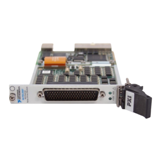
Summary of Contents for NI PXI-2567
- Page 1 PXI-2567 Features 2024-03-28...
- Page 2 PXI-2567 Overview........
- Page 3 PXI-2567 Features PXI-2567 Overview PXI-2567 Pinout CH10 CH11 COM CH0:7 COM CH8:15 CH12 CH13 CH14 CH15 CH16 CH24 CH17 CH25 CH18 CH26 CH19 CH27 COM CH16:23 COM CH24:31 CH20 CH28 CH21 CH29 CH22 CH30 CH23 CH31 CH32 CH40 CH33 CH41...
- Page 4 TRIG OUT Trigger output connection +5 V 5 V power output connection +12 V 12 V power output connection PXI-2567 Hardware Diagram This figure shows the hardware diagram of the module. Ch 0 Ch 1 Ch 2 Ch 3 Ch 4...
- Page 5 PXI-2567 Features PXI-2567 Topology This figure describes the topology of the module. Module software name: 2567/Independent (NISWITCH_TOPOLOGY_2567_INDEPENDENT) Note Using two channels per relay, the module can also control 32 two-coil latching relays. Independent Topology Bank 1 of 8 Bank 2 of 8...
- Page 6 PXI-2567 Features Figure 1. Example Configuration Customer Setup PXI-2567 com0 com1 com2 com3 Relay com7 Common Ground Return To close the channel 7 relay, call niSwitch_Connect(vi, "ch7", "com7"). Alternatively, you can open and close relays by calling the niSwitch Relay Control VI or the niSwitch_RelayControl function.
- Page 7 K6, NISWITCH_VAL_CLOSE_RELAY) power on the other coil and open the relay. PXI-2567 Available 5 V and 12 V Sources The module has a 5 V and a 12 V source available to drive relays. The 5 V source, available on pin 58, can provide up to 1.25 A of current. The 12 V source, available on pin 19, can provide 0.50 A of current.
- Page 8 PXI-2567 Features Figure 3. PXI-2567 Internal Drive Power Fuse Locations NI xx67 DAUGHTER BOARD +5V Power F2A 125V +12V Power F0.75A 125V FOR PATENTS:ni.com/patents a. +5 V Fuse b. +12 V Fuse ni.com © 2024 National Instruments Corporation.


Need help?
Do you have a question about the PXI-2567 and is the answer not in the manual?
Questions and answers