Waterous PB18 Series Operation, Maintenance And Overhaul Instructions
Portable pumps
Hide thumbs
Also See for PB18 Series:
- Operation instructions manual (22 pages) ,
- Operation, maintenance and overhaul instructions (8 pages)

Related Manuals for Waterous PB18 Series


Summary of Contents for Waterous PB18 Series
- Page 1 Form Number: F-3027 Issue Date: Mar 28, 2024 PB18 Series Portable Pumps Operation, Maintenance, and Overhaul Waterous Company • 125 Hardman Avenue South • South Saint Paul, MN 55075 • (651) 450-5000 www.waterousco.com...
-
Page 2: Table Of Contents
Table of Contents Safety Disassembly Safety Precautions Preparing to Disassemble the Pump Safety and Instructional Decals Tools Required Best Practices Introduction Optional Equipment Using this Document Removing the Pump Viewing the Document Electronically Disassembling the Pump Components Printing the Document PB18 Additional Documentation Removing the Priming Tube... - Page 3 Assembly Preparing to Assemble the Pump Tools Required Best Practices Optional Equipment Assembling the Pump Components Installing the Pump Understanding the Illustrations PB18 Assembling the Adapter Installing the Adapter Installing the Mechanical Seal Installing the Impeller Installing the Pump Body Installing the Priming Tube PB18-G Installing the Oil Seal...
-
Page 4: Safety
• Read and understand all the notices and safety precautions. operating or overhauling the equipment. • Do not operate the equipment when safety guards are removed. • Contact Waterous when you have questions about operating, maintaining, or • Do not modify the equipment. overhauling the equipment. - Page 5 Safety Introduction Overview Operation Maintenance Disassembly Assembly Troubleshooting Safety Precautions NOTICE NOTICE NOTICE Before Operation Freeze Damage Maintenance • Do not allow fluid in the • Read and understand all the • Not following maintenance instructions provided. lines to freeze. procedures can damage •...
-
Page 6: Safety And Instructional Decals
Safety Introduction Overview Operation Maintenance Disassembly Assembly Troubleshooting Safety and Instructional Decals Locate and review the safety decals. Replace any decals that are damaged or missing. Carbon Monoxide Warning Sound Level Warning Hot Surface Warning... -
Page 7: Introduction
Assembly Troubleshooting Using this Document Use this document to operate and overhaul your Waterous equipment. Understand the following conditions before continuing with the document: Use the guidelines below when viewing this document. • The instructions may refer to options or equipment that you have not Viewing the Document Electronically purchased with your system. -
Page 8: Symbols
Safety Introduction Overview Operation Maintenance Disassembly Assembly Troubleshooting Symbols Symbols are used to illustrate additional tools or operations that are required to complete the instructions. Anti-seize compound—This symbol tells you to apply the appropriate anti-seize compound to the part. Arbor press—This symbol tells you to use an arbor press to complete this step. Discard—This symbol tells you to discard or recycle the part in accordance with local regulations. - Page 9 Notes...
-
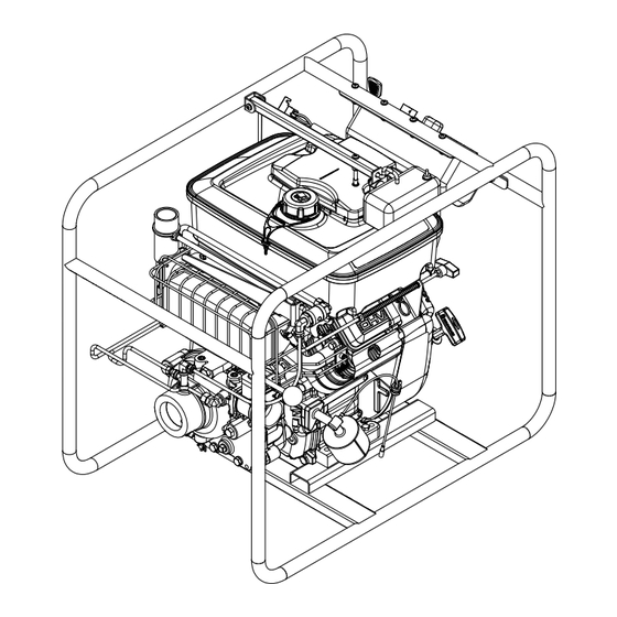
Page 10: Overview
Safety Introduction Overview Operation Maintenance Disassembly Assembly Troubleshooting System Components—PB18 (Pump End) - Page 11 Safety Introduction Overview Operation Maintenance Disassembly Assembly Troubleshooting System Components—PB18 (Pump End) Feature Feature Description Description Wrap-around frame—optional This supports the unit and provides mounting options. Fuel tank This stores the fuel that powers the engine. Exhaust primer This uses the exhaust gas from the engine to prime the pump. Muffler This dampens the sound created by the engine.
-
Page 12: System Components-Pb18 (Engine End)
Safety Introduction Overview Operation Maintenance Disassembly Assembly Troubleshooting System Components—PB18 (Engine End) - Page 13 Safety Introduction Overview Operation Maintenance Disassembly Assembly Troubleshooting System Components—PB18 (Engine End) Feature Feature Description Description Engine This powers the system. Refer to the manufacturer's instructions to locate additional features and controls. Choke control This is used to open and close the choke valve. Prime control This is used to operate the primer.
-
Page 14: System Components-Pb18-G (Pump End)
Safety Introduction Overview Operation Maintenance Disassembly Assembly Troubleshooting System Components—PB18-G (Pump End) - Page 15 Safety Introduction Overview Operation Maintenance Disassembly Assembly Troubleshooting System Components—PB18-G (Pump End) Feature Feature Description Description Wrap-around frame—optional This supports the unit and provides mounting options. Fuel tank This stores the fuel that powers the engine. Exhaust primer This uses the exhaust gas from the engine to prime the pump. Muffler This dampens the sound created by the engine.
-
Page 16: System Components-Pb18-G (Engine End)
Safety Introduction Overview Operation Maintenance Disassembly Assembly Troubleshooting System Components—PB18-G (Engine End) - Page 17 Safety Introduction Overview Operation Maintenance Disassembly Assembly Troubleshooting System Components—PB18-G (Engine End) Feature Feature Description Description Engine This powers the system. Refer to the manufacturer's instructions to locate additional features and controls. Choke control This is used to open and close the choke valve. Prime control This is used to operate the primer.
-
Page 18: Control Panel
Safety Introduction Overview Operation Maintenance Disassembly Assembly Troubleshooting Control Panel in.Hg... -
Page 19: Operation
Safety Introduction Overview Operation Maintenance Disassembly Assembly Troubleshooting Control Panel Feature Feature Description Description Panel LED This illuminates the panel during pump operation. Intake pressure gauge This measures the water pressure (psi/bar) at the pump intake. Discharge pressure gauge This measures the water pressure (psi/bar) at the pump discharge. Ignition switch This is used to start the engine. -
Page 20: Installing The Battery
Safety Introduction Overview Operation Maintenance Disassembly Assembly Troubleshooting Installing the Battery Use the illustration and instructions to connect the battery to the engine. Fully charge the battery before installing it. Battery requirements: • 12N14-3A battery • Capacity: 14 amp hours •... -
Page 21: Preparing For Operation
Safety Introduction Overview Operation Maintenance Disassembly Assembly Troubleshooting Preparing for Operation Use the illustrations and instructions to prepare the system for operation. Refer to the manufacturer's instructions to fill the engine and fuel tank. To add oil to the gear case (PB18-G units only), refer to: "Adding the Gear Case Oil"... -
Page 22: Starting The Engine
Safety Introduction Overview Operation Maintenance Disassembly Assembly Troubleshooting Starting the Engine Use the illustrations and instructions to start the engine. Refer to the manufacturer's instructions before operating the engine. Low oil: May cause loss of engine power, personal injury, or property damage. Check the oil regularly to maintain the correct level. -
Page 23: Priming The Pump
Safety Introduction Overview Operation Maintenance Disassembly Assembly Troubleshooting Priming the Pump Use the illustrations and instructions to prime the pump. Close the discharge valve. Start the engine. Refer to: "Starting the Engine" on page 22. Move the throttle toward the Fast position. a. -
Page 24: Operating The Pump
Safety Introduction Overview Operation Maintenance Disassembly Assembly Troubleshooting Operating the Pump Use the illustrations and instructions to operate the pump. Two methods can be used to adjust pump performance during operation: adjusting the discharge valve or adjusting the throttle. Pump overheating: May cause personal injury or pump damage. -
Page 25: Pumping From The Water Tank
Safety Introduction Overview Operation Maintenance Disassembly Assembly Troubleshooting Pumping from the Water Tank Use the illustration and instructions to operate the pump from the water tank. Note: Do not pump more water than is available from the water tank. Make sure that the intake pressure stays above 0 psi (0 bar). -
Page 26: Pumping From A Hydrant Or Relay
Safety Introduction Overview Operation Maintenance Disassembly Assembly Troubleshooting Pumping from a Hydrant or Relay Use the illustrations and instructions to operate the pump from a hydrant or relay pumper. Note: Do not pump more water than is available from the hydrant or relay pumper. Make sure that the intake pressure stays above 0 psi (0 bar). -
Page 27: Pumping From Draft
Safety Introduction Overview Operation Maintenance Disassembly Assembly Troubleshooting Pumping from Draft Use the illustration and instructions to operate the pump from draft. To achieve the best results, do the following: • Position the unit close to the water supply. • Position the intake hose so that no part of it is higher than the pump intake. -
Page 28: After Operation
Safety Introduction Overview Operation Maintenance Disassembly Assembly Troubleshooting After Operation Use the illustrations and instructions to stop the engine and drain the unit for storage. Freezing water: May cause pump damage. If the pump is exposed to freezing temperatures, drain all water from the pump, lines, and any accessories. -
Page 29: Maintenance
Safety Introduction Overview Operation Maintenance Disassembly Assembly Troubleshooting Maintenance Schedule Perform the following procedures at the recommended intervals at a minimum. Environmental conditions affect the maintenance requirements. Inspect the components frequently and create a maintenance schedule suitable to your application and environment. Replace wear components with equivalent components. Use your serial number to gain access to the service parts lists associated with your system through the MyWaterous login at www.waterousco.com. -
Page 30: Checking The Gear Case Oil Level
Safety Introduction Overview Operation Maintenance Disassembly Assembly Troubleshooting Checking the Gear Case Oil Level Use the illustration and instructions to check the gear case oil level. Note: Make sure that the unit is level before checking the gear case oil level. Remove the oil level plug. -
Page 31: Adding The Gear Case Oil
Safety Introduction Overview Operation Maintenance Disassembly Assembly Troubleshooting Adding the Gear Case Oil Use the illustrations and instructions to add oil to the gear case. Use approximately 1 pt (0.47 L) of SAE 90 gear oil. Arrange a funnel to direct oil into the gear case. -
Page 32: Draining The Gear Case Oil
Safety Introduction Overview Operation Maintenance Disassembly Assembly Troubleshooting Draining the Gear Case Oil Use the illustrations and instructions to drain the oil in the gear case. Place a suitable container under the gear case to collect the drained oil. Remove the magnetic drain plug. Clear any debris that may have adhered to the plug. -
Page 33: Replacing The Spark Arrestor
Safety Introduction Overview Operation Maintenance Disassembly Assembly Troubleshooting Replacing the Spark Arrestor Use the illustrations and instructions to replace the spark arrestor inside the primer. Remove the screw and nut securing the butterfly valve to the primer rod, then remove the butterfly valve. - Page 34 Safety Introduction Overview Operation Maintenance Disassembly Assembly Troubleshooting Replacing the Spark Arrestor Use the illustrations and instructions to replace the spark arrestor inside the primer. Install the new spark arrestor. Install the screw. Use the mounting hardware to secure the primer assembly to the primer adapter.
-
Page 35: Disassembly
• This equipment is intended to be disassembled by a person or persons with the basic knowledge of servicing similar equipment. Contact Waterous for Disassembling the Pump Components more information. -
Page 36: Pb18
Safety Introduction Overview Operation Maintenance Disassembly Assembly Troubleshooting PB18 Removing the Priming Tube Use the illustration and instructions to remove the priming tube. Note: Remove any intake or discharge piping that may interfere with overhaul procedures. Remove the tube connecting the priming valve to the pump intake. -
Page 37: Removing The Pump Body
Safety Introduction Overview Operation Maintenance Disassembly Assembly Troubleshooting PB18 Removing the Pump Body Use the illustrations and instructions to remove the pump body. Remove the pump body hardware, then remove the pump body from the adapter. Remove the wear ring. Note: If needed, there are 10-32 tapped holes to aid in removing the wear ring. -
Page 38: Removing The Impeller
Safety Introduction Overview Operation Maintenance Disassembly Assembly Troubleshooting PB18 Removing the Impeller Use the illustration and instructions to remove the impeller. Note: The muffler guard has been removed from the illustration to provide a clear view of the impeller and related components. Remove the impeller hardware, then remove the impeller. -
Page 39: Removing The Mechanical Seal
Safety Introduction Overview Operation Maintenance Disassembly Assembly Troubleshooting PB18 Removing the Mechanical Seal Use the illustration and instructions to remove the mechanical seal. Note: The muffler guard has been removed from the illustration to provide a clear view of the mechanical seal and related components. -
Page 40: Removing The Adapter
Safety Introduction Overview Operation Maintenance Disassembly Assembly Troubleshooting PB18 Removing the Adapter Use the illustrations and instructions to remove the engine adapter. Remove the adapter hardware, then remove the adapter. Remove the shaft sleeve. Remove the O-ring. -
Page 41: Disassembling The Adapter
Safety Introduction Overview Operation Maintenance Disassembly Assembly Troubleshooting PB18 Disassembling the Adapter Use the illustrations and instructions to disassemble the engine adapter. Press the mechanical seal stationary ring from the adapter. Remove the O-ring. Remove the wear ring. Note: If needed, there are 10-32 tapped holes to aid in removing the wear ring. -
Page 42: Pb18-G
Safety Introduction Overview Operation Maintenance Disassembly Assembly Troubleshooting PB18-G Removing the Priming Tube Use the illustration and instructions to remove the priming tube. Note: Remove any intake or discharge piping that may interfere with overhaul procedures. Remove the tube connecting the priming valve to the pump intake. -
Page 43: Removing The Pump Body
Safety Introduction Overview Operation Maintenance Disassembly Assembly Troubleshooting PB18-G Removing the Pump Body Use the illustrations and instructions to remove the pump body. Remove the pump body hardware, then remove the pump body from the gear case. Use pry bars to remove the wear ring. -
Page 44: Removing The Impeller
Safety Introduction Overview Operation Maintenance Disassembly Assembly Troubleshooting PB18-G Removing the Impeller Use the illustrations and instructions to remove the impeller. Remove the impeller hardware, then use pry bars to remove the impeller. Remove the key. Remove the mechanical seal bellows and primary ring. -
Page 45: Removing The Gear Case Cover
Safety Introduction Overview Operation Maintenance Disassembly Assembly Troubleshooting PB18-G Removing the Gear Case Cover Use the illustration and instructions to remove the gear case cover. To drain the gear case oil before removing the cover, refer to: "Draining the Gear Case Oil"... -
Page 46: Disassembling The Cover
Safety Introduction Overview Operation Maintenance Disassembly Assembly Troubleshooting PB18-G Disassembling the Cover Use the illustrations and instructions to disassemble the gear case cover. Remove the impeller gasket. Use pry bars to remove the wear ring. Remove the O-ring. Press the impeller shaft assembly out of the gear case cover, then remove the oil seal if it was not pressed out with the impeller shaft. -
Page 47: Disassembling The Impeller Shaft
Safety Introduction Overview Operation Maintenance Disassembly Assembly Troubleshooting PB18-G Disassembling the Impeller Shaft Use the illustration and instructions to disassemble the impeller shaft assembly. Remove the bearing. -
Page 48: Removing The Drive Gear
Safety Introduction Overview Operation Maintenance Disassembly Assembly Troubleshooting PB18-G Removing the Drive Gear Use the illustration and instructions to remove the drive gear. Remove the drive gear hardware, then remove the drive gear. Remove the key. -
Page 49: Removing The Gear Case
Safety Introduction Overview Operation Maintenance Disassembly Assembly Troubleshooting PB18-G Removing the Gear Case Use the illustrations and instructions to remove the gear case. Remove the gear case hardware, then remove the gear case. Remove the shaft sleeve. Remove the O-ring. -
Page 50: Disassembling The Gear Case
Safety Introduction Overview Operation Maintenance Disassembly Assembly Troubleshooting PB18-G Disassembling the Gear Case Use the illustration and instructions to disassemble the gear case. Remove the oil seal. If needed, clean the breather. -
Page 51: Preparing To Assemble The Pump
• Tighten hardware to industry standard torque specification—unless otherwise • This equipment is intended to be assembled by a person or persons with the noted. basic knowledge of servicing similar equipment. Contact Waterous for more information. • Make sure that you do not over-tighten plugs. -
Page 52: Pb18
Safety Introduction Overview Operation Maintenance Disassembly Assembly Troubleshooting PB18... -
Page 53: Assembling The Adapter
Safety Introduction Overview Operation Maintenance Disassembly Assembly Troubleshooting PB18 Assembling the Adapter Use the illustrations and instructions to assemble the engine adapter. Apply anti-seize compound to the outside of the wear ring, then install it into the adapter. Install the O-ring into the O-ring groove. Apply lubricant to the outside of the mechanical seal stationary ring, then press it into the adapter with the chamfered edge... -
Page 54: Installing The Adapter
Safety Introduction Overview Operation Maintenance Disassembly Assembly Troubleshooting PB18 Installing the Adapter Use the illustrations and instructions to install the engine adapter. Apply lubricant to the shaft, then install the O-ring. Install the shaft sleeve. Use the adapter hardware to secure the adapter to the engine. -
Page 55: Installing The Mechanical Seal
Safety Introduction Overview Operation Maintenance Disassembly Assembly Troubleshooting PB18 Installing the Mechanical Seal Use the illustration and instructions to install the mechanical seal. Note: The muffler guard has been removed from the illustration to provide a clear view of the mechanical seal and related components. -
Page 56: Installing The Impeller
Safety Introduction Overview Operation Maintenance Disassembly Assembly Troubleshooting PB18 Installing the Impeller Use the illustration and instructions to install the impeller. Note: The muffler guard has been removed from the illustration to provide a clear view of the impeller and related components. Insert the key into the key slot. -
Page 57: Installing The Pump Body
Safety Introduction Overview Operation Maintenance Disassembly Assembly Troubleshooting PB18 Installing the Pump Body Use the illustrations and instructions to install the pump body. Apply anti-seize compound to the outside of the wear ring, then install it into the pump body. Use the pump body hardware to secure the pump body to the adapter. -
Page 58: Installing The Priming Tube
Safety Introduction Overview Operation Maintenance Disassembly Assembly Troubleshooting PB18 Installing the Priming Tube Use the illustration and instructions to install the priming tube. Connect the tube to the priming valve and pump intake. -
Page 59: Pb18-G
Safety Introduction Overview Operation Maintenance Disassembly Assembly Troubleshooting PB18-G... -
Page 60: Installing The Oil Seal
Safety Introduction Overview Operation Maintenance Disassembly Assembly Troubleshooting PB18-G Installing the Oil Seal Use the illustration and instructions to install the oil seal into the gear case. Apply sealant around the oil seal, then install it into the gear case. -
Page 61: Installing The Gear Case
Safety Introduction Overview Operation Maintenance Disassembly Assembly Troubleshooting PB18-G Installing the Gear Case Use the illustrations and instructions to install the gear case. Apply lubricant to the shaft, then install the O-ring. Install the shaft sleeve. Use the gear case hardware to secure the gear case to the engine. -
Page 62: Installing The Drive Gear
Safety Introduction Overview Operation Maintenance Disassembly Assembly Troubleshooting PB18-G Installing the Drive Gear Use the illustration and instructions to install the drive gear. Insert the key into the key slot. Install the drive gear onto the shaft, then use the drive gear hardware to secure it. -
Page 63: Assembling The Impeller Shaft
Safety Introduction Overview Operation Maintenance Disassembly Assembly Troubleshooting PB18-G Assembling the Impeller Shaft Use the illustration and instructions to assemble the impeller shaft assembly. Apply grease to the shaft, then press the bearing onto the shaft. -
Page 64: Assembling The Cover
Safety Introduction Overview Operation Maintenance Disassembly Assembly Troubleshooting PB18-G Assembling the Cover Use the illustrations and instructions to assemble the gear case cover. Apply lubricant to the outside of the mechanical seal stationary ring, then press it into the cover with the chamfered edge facing in. - Page 65 Safety Introduction Overview Operation Maintenance Disassembly Assembly Troubleshooting PB18-G Assembling the Cover Use the illustrations and instructions to assemble the gear case cover. Apply grease to the bore of the cover, then press the impeller shaft assembly through the cover. Apply lubricant to the O-ring groove, then install the O-ring into the groove.
-
Page 66: Installing The Gear Case Cover
Safety Introduction Overview Operation Maintenance Disassembly Assembly Troubleshooting PB18-G Installing the Gear Case Cover Use the illustration and instructions to install the gear case cover. Install the gasket between the gear case and cover. Use the cover hardware to secure the cover to the gear case. -
Page 67: Installing The Impeller
Safety Introduction Overview Operation Maintenance Disassembly Assembly Troubleshooting PB18-G Installing the Impeller Use the illustrations and instructions to install the impeller. Apply lubricant to the inside of the impeller and inside of the mechanical seal bellows, then install the mechanical seal bellows and primary ring into the impeller. -
Page 68: Installing The Pump Body
Safety Introduction Overview Operation Maintenance Disassembly Assembly Troubleshooting PB18-G Installing the Pump Body Use the illustrations and instructions to install the pump body. Apply anti-seize compound to the outside of the wear ring, then install it into the pump body. Use the pump body hardware to secure the pump body to the gear case. -
Page 69: Installing The Priming Tube
Safety Introduction Overview Operation Maintenance Disassembly Assembly Troubleshooting PB18-G Installing the Priming Tube Use the illustration and instructions to install the priming tube. Connect the tube to the priming valve and pump intake. -
Page 70: Troubleshooting
Safety Introduction Overview Operation Maintenance Disassembly Assembly Troubleshooting Troubleshooting Guide Symptom Symptom Possible Cause Possible Cause Solution Solution The pump fails to prime or loses There is a leak in the system. Clean and tighten all intake connections and make sure that the hoses and gaskets are in working condition—repair or prime. - Page 71 Safety Introduction Overview Operation Maintenance Disassembly Assembly Troubleshooting Symptom Symptom Possible Cause Possible Cause Solution Solution The pump capacity is insufficient. The engine is not providing enough The engine requires maintenance—repair according to the manufacturer's instructions. power. The impeller and/or wear rings are Replace the impeller and wear rings.
- Page 72 Waterous Company 125 Hardman Avenue South South Saint Paul, MN 55075 (651) 450-5000 www.waterousco.com...
Need help?
Do you have a question about the PB18 Series and is the answer not in the manual?
Questions and answers