HANGCHA XC Series Operation And Maintenance Manual
Electric reach truck
Hide thumbs
Also See for XC Series:
- Operation and maintenance manual (95 pages) ,
- Operation and maintenance manual (110 pages) ,
- Operation and maintenance manual (87 pages)
Table of Contents
Troubleshooting

Related Manuals for HANGCHA XC Series


Summary of Contents for HANGCHA XC Series
- Page 1 Series CQD14-XC4-SI CQD14-XC4D-SI Electric Reach Truck CQD16-XC4-SI CQD16-XC4D-SI CQD18-XC4-SI CQD18-XC4D-SI CQD20-XC4-SI CQD20-XC4D-SI CQD25-XC4-SI CQD25-XC4D-SI Operation and Maintenance Manual Original Instruction HANGCHA GROUP CO., LTD. Dec. 2021...
-
Page 2: Foreword
Thank you very much for purchasing forklift truck of Hangcha Group. XC series stand-on lithium battery electric reach truck is applicable for operation in narrow passages and limited spaces. It has a small turning radius and is an ideal tool for handling goods in warehouse, supermarket and workshop. -
Page 3: Table Of Contents
Content FOREWORD..............................2 Part One Operation and Maintenance....................1 1.Notice for use............................... 1 2.Truck introduction............................1 3.Main part and name............................ 3 4.Safety instructions............................. 10 5.Structure and stability of truck.........................14 6.During breaking-in............................. 17 7.Routine Maintenance..........................18 8.Drive and operate............................20 9.Storage................................23 10.lithium battery............................24 11.Lithium battery charge.......................... -
Page 4: Part One Operation And Maintenance
Part One Operation and Maintenance Notice for use 1.1 General Truck in this manual is only for lifting and transporting loads. It must be used, operated and maintained according to the information in this manual. Any other uses are outside the design envelope and can lead to injury to persons or damage to equipment and property. - Page 5 1.3 Approved application conditions - Used in specified area as factory, tourist attraction and recreation place. - Operation only on secure, level surfaces with sufficient capacity. - Operation only on routes that are visible and approved by the proprietor. - Use in specified rated load. -...
- Page 6 1.4 Obligations and responsibilities of the equipment user In this operation manual, "equipment user" refers to any natural or legal person who directly uses or appoints others to use this forward-moving vehicle. In special circumstances such as leasing and leasing, the "equipment user" represents the party who undertakes the prescribed operating obligations in accordance with the contract terms between the equipment owner and the user.
-
Page 7: Truck Introduction
Truck introduction 2.1 General XC series stand-on lithium battery electric reach truck described in this manual should work under low working strength. Users can get relevant information as rated load from the product model. CQD25-XC4D-SI Meaning Electric pallet truck Rated load capacity×100kg... - Page 8 2.2 Function description XC series stand-on lithium battery electric reach truck Fully utilized the advantages of the lithium battery dedicated platform, and made major breakthroughs in vehicle structure, functional configuration, performance parameters, and ergonomics. Novel style, simple interior Make full use of the compact advantages of lithium batteries, break through the traditional body structure design, and make the vehicle style more powerful.
-
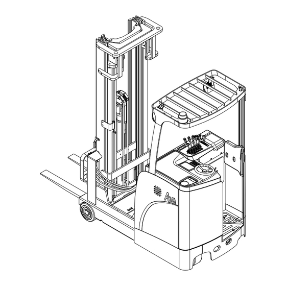
Page 9: Main Part And Name
3.Main part and name 3.Seat armrest (Push rod for 1.Mast 2.Overhead guard 4.Seat mechanical valve type) 5.Hood 6.Driving wheel 7.Bearing wheel 8.Headlamp 12.Liftable 9.Steering wheel 10.Brake pedal 11.Safety pedal step platform 13.acceleration pedal 14.meter 15.password keyboard 16.tank 17.Oil pump motor 18.fan 19.Steering motor 20.motor... - Page 10 3. Shift the fork frame 1. Direction switch 2. Horn from left to right 4. Tilt the fork frame back and 5. Move the mast back 6. Lifting and lowering the forth and forth mast 8. Pedal electric lifting 9. The front is a one-key 7.
- Page 11 Instrumentation and control Basic interface ①Information bar, including: height/time/weight Height value display format (need to be displayed all the time): *.**m(MAX *.**m) If the meter is not equipped with the lifting height of the free cylinder mast When checking (the controller sends the instrument through PDO to check whether the mast is equipped with a free cylinder to check the lifting height of the mast), it will display "m(MAX *.**m)"...
- Page 12 Boot interface— password If the user has enabled the power-on password function, the 3401T instrument system will automatically enter the power-on password interface after displaying the Logo interface. According to the different settings, you can enter the password through the 3401T instrument keys or through the ECS electronic password lock provided by Curtis to swipe the card or enter the password.
- Page 13 Main interface icon icon name icon name icon name icon name Vehicle Fork down Fork shift left breakdow Traverse Safety maintenance Fork rise Fork shift right pedal Potential Fork shift energy Turtle speed Fork forward recovery right indicator The battery Fork shift Fork Lift limit...
- Page 14 Battery level display on the main interface The battery power icon on the main interface of the 3401T instrument has a total of 10 power indicator bars, and is displayed in three colors according to different power conditions, as shown in the following figure: Power 90%~100%: Display 10 green power indicator bars;...
- Page 15 USER password/OEM password The 3401T instrument has set two levels of authority menu options for the user, as shown in the figure above, as shown in the figure above, when "user password"/"USER" is selected, and the corresponding user password is entered, the meter enters the user level Menu; when "OEM password"/"OEM"...
-
Page 16: Safety Instructions
4.Safety instructions 1. Only tr ained and accredited operators are permitted to operate the forklift truck. 6. Batteries generate explosive gases. Keep sparks and open flames away from the battery. 2. Have a discussion and make plans before Keep tools away from the battery terminals to working. - Page 17 19. When the mast of reach truck reaching out, do not drive it because of in this status, the truck has the trend of overturn when a sudden brake or turning. The truck must be driven 13. Know well the curve chart on the load when the mast shrinks to the bottom.
- Page 18 forbidden to turn around suddenly on a slope. 26. When operating loaded truck, drive forward to downhill and reverse to uphill. When operating unloaded truck, drive forward to uphill and reverse to downhill.(note: fork direction is back) 30. Do not use the truck, when the weather is bad, such as sand blowing by wind, snowing, thunder, flashing, rainstorm and typhoon etc.
- Page 19 and flat cement, asphalt or concrete surfaces. modification or alteration to a powered When there are snows, ice accretion, hydrops, industrial truck provided, however, that the or other foreign matter and obstacle, operate user shall::①Arrange for the modification or the forklift only after cleaning them, otherwise alteration designed, tested...
-
Page 20: Structure And Stability Of Truck
(Avoid truck tipping over!) 5. Structure and stability of truck It is very important for operator to know the truck’s structure and relationship between load and stability. The structure Caution of the truck The basic structure of the truck is lifting device (include mast and forks) and truck body. - Page 21 Gravity Caution stability The combined center that is composed of the barycenter and the load center determine the stability of lift trucks. When unloaded, the barycenter does not change; When loaded, the barycenter is determined by the truck and the load’s center. The barycenter is also determined by the tilting, lifting, reaching of the mast.
- Page 22 the max load(weight and Caution load center) The distance between the load center and the front surface of forklift or load bracket (select the min) on the forklift is called LOAD CENTER DISTANCE. The max gravity that the truck can load is called MAX LOAD on condition that the load is on the load center distance.
-
Page 23: During Breaking-In
6. During breaking-in We recommended operating the reach truck under light load conditions for the first stage of operation to get the most from it. Especially the requirements given below should be observed while the machine is in a stage of 100 hours of operation.: In general, the battery should be recharged promptly when the charge level has decreased to 20% of its capacity. -
Page 24: Routine Maintenance
bearing is damaged. 7. Routine Maintenance Careful, all-round maintenance will keep the 6. Electromagnetic brake forklift truck in good working condition. It Press the parking brake rocker switch on the guarantees the safety of the forklift and your instrument stand, and the parking brake personal safety at work. - Page 25 11. Safety pedal Put your left foot on the safety pedal, inspect if all functions are normal when the truck is in forward/backward position. 12. Check the brake pedal Step down the brake pedal, and check the electromagnetic brake of the front wheel. 13.
-
Page 26: Drive And Operate
8. Drive and operate Caution · Be careful of getting on or off the truck. Warning Don’t jump out of the truck. If any damage or fault is found, don’t · Don’t park the reach truck on the operate truck until being corrected. running route. - Page 27 stacked. 1. Insert the forks into loads and lift loads about 350-450mm off the ground; 2. Backward the mast to the end, and travel to stacking place. Stacking load When approaching the deposit area, slow down your truck. Stop the truck right in front of the area where your load is to be deposited.
- Page 28 Warning: Caution When mast reaches If the forks are hard to be fully inserted, out, it is forbidden to press reach fingertip to insert 3/4 of the lifting lowering forks. Raise the forks 5 to 10cm and move loads high backward 10 to 20cm with the pallet or skid position without shelf on the forks, and then lower the pallet or...
-
Page 29: Storage
9. Storage Raise the forklift just enough to allow it Daily storage to be placed onto the wooden support blocks. Park the forklift in a designated area, Place wooden blocks of identical size lower the mast and move it backward in under left and right sides of the frame. -
Page 30: Lithium Battery
10.lithium battery Safety warning 1.1 Do not short-circuit the positive and negative poles of the battery under any circumstances, do not heat the battery, or throw the battery into water; 1.2 The new factory battery pack must be fully charged before use; 1.3 Never mix different brands, different types, different capacities, and new and old batteries;... - Page 31 Basic terminology and use environmental conditions of lithium ion power battery Basic terms and definitions 3.1.1 Nominal voltage Used to express the battery voltage-an appropriate approximate value; 3.1.2 Rated capacity Under the specified conditions, the battery is fully charged and can provide the capacity value stated by the manufacturer's trademark;...
- Page 32 Use the basic environment 3.2.1 Charging temperature: 0℃~45℃;: Discharging temperature: -20℃~50℃: The best use temperature is 15℃~35℃; 3.2.2 The operating environment humidity HR≤85%, the battery should be kept as dry as possible for use; 3.2.3 When charging the battery, try to make shallow charge and discharge as much as possible to increase battery life.
- Page 33 Basic requirements for installation of lithium-ion power battery 4.2.1 The battery pack must be installed in the correct direction, and do not install it upside down or reverse. 4.2.2 Do not violently disassemble and assemble to avoid personal and property damage. Basic requirements for lithium-ion power battery connection 4.3.1 During the battery connection operation, make sure that the port is plugged in correctly and in place;...
- Page 34 otherwise it will easily damage the battery safety protection device and bring hidden dangers of insecurity; 4. Avoid using the battery pack under high temperature (in direct sunlight) for a long time, otherwise it may cause the battery to overheat, or function failure, and shorten the life span; 5.
- Page 35 Warning There will generate combustible and explosive gas when charging, please open the cover and make sure no covering on the battery, make sure each battery filling cap is opened, keep in good ventilated place and no flame in the charging area. ake out the battery charging plug from the truck outlet, connect to the charger plug.
-
Page 36: Lithium Battery Charge
11.Lithium battery charge SLC-80200/ SLC-80100 Operation instructions for intelligent charger (CATL battery charger) Start-up interface Start-up interface Click on the icon: , Enter the help description interface. Click on the icon: , on-off alarm sound, to turn on the alarm sound state, turn off the alarm sound state. - Page 37 Help interface Click on the icon: , return to main interface. Click on the reservation icon to set the time for booking mode. The default password is 123456. Click on the icon : , enter the password input interface, enter the correct password into the factory parameter setting interface Password entry interface Enter the correct password in the password entry box.
- Page 38 Password modification interface Enter in sequence according to the prompt: Enter the user's old password, enter the new password for the first time and enter the new password for the second time. Click on the icon: , if the user's old password is entered correctly, the first time the new password is entered and the second time the new password is entered, the modification is successful.
- Page 39 Power module information display interface Click on the icon: , switch module information backward. Click on the icon:, return to the main interface. Click on the icon: , switch module information forward. Display single power module output voltage, output current, various operating conditions. Charging process explanation The charging step:...
- Page 40 5. The "working" light is bright green. When the "output voltage" is similar to the "battery voltage", the charging motor outputs the relay to absorb and the charging machine officially begins to charge the battery. At this point, "output current" and "output voltage" will be output according to "current demand"...
- Page 41 User wiring instruction Output DC Plug Input AC Plug AC input air switch power supply. The input is an Yida plug and the output is a charging gun. Warning: PE protection of the earth must be connected, otherwise it may threaten life safety.
- Page 42 2.Power check Make sure that AC input zero wire and DC output positive and negative electrode wiring are correct, and that there is no short circuit in input and output; The input voltage and frequency are normal; At any time in the state of electricity.Offline online charging lines can not be connected at the same time.
-
Page 43: Maintenance
debris on each port, or metal terminal 6.Charging procedures: damaged or influenced by rust or Stop the truck, turn off the key switch, corrosion. and the truck is disconnected. Pull up the four-wheel pedals on the charger tray, pull the charger to a proper position, step down four pedals to prevent movement. - Page 44 ·Inspection and maintenance are often easily overlooked. Early detection enables problems to be settled in a timely manner. ·Use original Hangcha Group spare parts. ·Do not use different types of oil when changing or topping up oil. ·Waste oil and battery fluid must not be poured away indiscriminately, but recycled or disposed of in accordance with local environmental laws and regulations.
-
Page 45: Periodic Maintenance Schedule
13.Periodic maintenance schedule 〇—check, correct, adjust Battery ×—replace Every 3 Every 6 Service Daily Weekly Monthly Item Tool months months required (8h) (40h) (166h) (500h) (1000h) Visual 〇 〇 〇 〇 Electrolyte level inspection Electrolyte 〇 〇 〇 〇 Hydrometer specific gravity 〇... - Page 46 Motor Every 3 Every 6 Service Daily Weekly Monthly Item Tool months months required (8h) (40h) (166h) (500h) (1000h) Clear foreign 〇 〇 〇 bodies on motor housing Clean or replace 〇 bearings Check wear condition of carbon 〇or× 〇or× brushes, commutators, check spring force...
- Page 47 〇 〇 〇 〇 〇 Check for noise Check for rope 〇 〇 〇 〇 〇 winding the wheels Steering system Every 3 Every 6 Service Daily Weekly Monthly Item Tool months months required (8h) (40h) (166h) (500h) (1000h) Check 〇...
- Page 48 Leaks, looseness, 〇 〇 〇 rupture, deformation, damage × Replace pipes years Hydraulic Check pump for leaks 〇 〇 〇 〇 〇 and noise pump Check for oil leakage 〇 〇 〇 or noise Motor 〇 〇 〇 If work normally...
- Page 49 Lifting system Every 3 Every 6 Daily Weekly Monthly Item Service required Tool months months (8h) (40h) (166h) (500h) (1000h) Check chain tension, check for 〇 〇 〇 〇 〇 deformation, damage and corrosion 〇 〇 〇 Lubricate chain Riveting pins 〇...
- Page 50 head guide bolts for looseness Check rollers, roller 〇 〇 〇 pins and welded parts for cracks or damage Control system Every 3 Every 6 Daily Weekly Monthly Item Service required Tool months months (8h) (40h) (166h) (500h) (1000h) Check brake 〇...
- Page 51 Steering, lifting chain 2~4 Hydraulic system high-pressure hoses Hydraulic system inner seals and rubber parts Bolt tightening torque table N·m Unit If not specified, the thread tightening torque can be selected from the table below: Bolt’s diameter 8.8 Grade 8.0~8.5 8.5~10.2 20.7~24.8 40.9~49...
-
Page 52: Conveying And Lifting Of The Truck
14.Conveying and lifting of the truck Convey ·Forklift trucks are generally used for loading, unloading and short-distance transportation. They are not designed to be a long-distance mode of transport. For long-distance transportation of forklifts, they need to be transported by ships, trains or vehicles with a load of more than 5 tons. Assemble and disassemble the forklift with loading platform or lifting device. -
Page 53: Main Technical Parameter
15.Main technical parameter CQD14-XC4-SI CQD16-XC4-SI CQD18-XC4-SI CQD20-XC4-SI CQD25-XC4-SI Model CQD14-XC4D-SI CQD16-XC4D-SI CQD18-XC4D-SI CQD20-XC4D-SI CQD25-XC4D-SI Power unit Li-ION battery Li-ION battery Li-ION battery Li-ION battery Li-ION battery Manual Seated Seated Seated Seated Seated Rated capacity/rated Q(t) load Load centre distance c(mm) 1)7)11) 1)7)11) Load distance... - Page 54 CQD14-XC4-SI CQD16-XC4-SI CQD18-XC4-SI CQD20-XC4-SI CQD25-XC4-SI Model CQD14-XC4D-SI CQD16-XC4D-SI CQD18-XC4D-SI CQD20-XC4D-SI CQD25-XC4D-SI Fork carriage ISO Ⅱ A Ⅱ A Ⅱ A Ⅱ A Ⅱ A 4.23 2328, class/type A, B 4.24 Fork-carriage width (mm) Distance between 4.25 (mm) fork-arms Distance between 4.26 (mm) wheel arms...
- Page 55 CQD14-XC4-SI CQD16-XC4-SI CQD18-XC4-SI CQD20-XC4-SI CQD25-XC4-SI Model CQD14-XC4D-SI CQD16-XC4D-SI CQD18-XC4D-SI CQD20-XC4D-SI CQD25-XC4D-SI Battery voltage,nominal (V/Ah) 80/250 80/250 80/250 80/404 80/404 capacity K5 Battery voltage,rated 6.4.1 (V/Ah) 80/404 80/404 80/404 capacity K5,Optional Battery weight (±5% ) (kg) Operating pressure for 10.1 (bar) attachments 10.2 Oil flow for attachments...
- Page 56 1) h3>7000mm:-25mm。 2) h3>7000mm:-8mm。 3) h3>7000mm:+25mm。 4) h3>7000mm:-33mm。 5) h3>7000mm:+19mm。 6) h3>7000mm:+23mm。 7) With optional battery 80V/404Ah,h3≤7000mm:-90mm。 8) With optional battery 80V/404Ah,h3≤7000mm:+90mm。 9) With optional battery 80V/404Ah,h3≤7000mm:+68mm。 10) With optional battery 80V/404Ah,h3≤7000mm:+82mm。 11) With optional battery 80V/404Ah,h3>7000mm:-115mm。 12) With optional battery 80V/404Ah,h3>7000mm:+115mm。 13) With optional battery 80V/404Ah,h3>7000mm:-123mm。...
- Page 58 Mast parameter table 1.4/1.6T Door frame Mast Lifting Free lift Tilt angle of retracted extension height height fork frame height height type α/β (°) 4000 2030 4965 1065 4500 2150 5465 1185 5000 2300 5965 1335 5500 2450 6465 1485 6000 2625 6965...
- Page 59 1.8T Door frame Mast Lifting Free lift Tilt angle of retracted extension height height fork frame height height type α/β (°) 4000 2085 4965 1120 4500 2165 5465 1200 5000 2315 5965 1350 5500 2490 6465 1525 6000 2665 6965 1700 6500 2835...
- Page 60 Load table 1.4t Load center distance(mm) Load table(kg) 900 1000 1100 1200 ≤6500 1400 1210 1070 920 7000 1350 1170 1030 880 7500 1300 1120 8000 1250 1080 Lifting 8500 1200 1030 height 9000 1100 (mm) 9500 1000 10000 10500 11000 1.6t Load center distance(mm)...
- Page 61 2.0t Load center distance(mm) Load table(kg) 1000 1100 1200 ≤6500 2000 1750 1560 1360 1200 1040 7000 1950 1710 1520 1330 1160 1010 7500 1900 1660 1480 1290 1130 8000 1850 1620 1440 1250 1090 8500 1800 1570 1400 1220 1060 9000 1700 1480 1320 1140 Lifting...
-
Page 62: Label And Name Plate
16.Label and name plate Stick different label and nameplate at different position of the truck. 载 荷 曲 线 图 实 际 起 重 量 起升高度 A Ⅵ 载 荷 中 心 距 Serial name number Load curve Nameplate Tonnage label: ×100kg Manufacturer label Manufacturer label Lifting point label... -
Page 63: Relevant Safety Directive Or Standard (Ce Or Optional)
17.Relevant safety directive or standard (CE or optional) After CE certificated, the truck meets the following directive and standard: – 2006/42/EC machinery directive(namely Directive of the council of the laws of the member states concerning machinery ), 2000/14/EC Noise Directive(Namely Directive of the council of the laws of the member states concerning noise radiation of outdoor equipment);... -
Page 64: Part Ii Structure, Principle And Maintenance
Part II Structure, principle and maintenance Drive steering system Drive system of electric reach truck is composed of AC traction motor, pivotal bearing, reduction gearbox, driving wheel, electromagnetic brake and so on. Steering system is composed of electromagnetic assisted steering gear, universal joint, transmission rod, steering wheel, etc. 1. -
Page 65: Reduction Gearbox
Reduction gearbox Brief introduction The truck adopts double reduction, the first stage adopts cylindric spiral gear reduction and the second stage adopts planetary reduction. This reduction gear box owns traits like small size, light weight, large transmission ratio, small radius of gyration, high efficient and simple structure, which can turn on site and equip with motor vertically thus cause the radius of gyration on the carriage small. -
Page 66: Structure Introduction
Structure introduction Refer to picture 2-3 for reduction gearbox structure, whose principle is listed before, reduction gearbox is directly driven by the drive motor through spline joint of drive gear, reducing speed by a couple of cylindrical gears and spiral bevel gears, which in meeting the transmission ratio condition, guarantees the high-efficient rotate of the reduction gear box and make small radius of gyration. - Page 67 Notice to installment and use: ①Before installing, you should wipe off the oil on the shell surface. In case that the oil leaks during use, you are not allowed to dismount and disassemble the product. ②Prevent the assembling surface and exposed flange from being knocked or damaged, otherwise it may influence the installment and use precision.
-
Page 68: Failures And Troubleshooting Measures
Failures and troubleshooting measures Fault Probable reason Phenomenon Corrective action Combined part bolts Retighten these bolts loosen Combined face journal sealing ring Replace sealing ring damage Gasket damage Replace gasket Steering wheel cannot return Spring leaf broken Replace spring leaf to the middle automatically Dial pin or universal Pressure... -
Page 69: Brake System
Brake system Electromagnetic brake Basic parameter:Rated voltage:42V DC Rated power:55W Rated torque:125N.m Working principle Sleeve bolt This brake is one-chip brake, owns two Armatrure friction surfaces. It can generate strong braking torque in the power-off position Fastening bolt by pressure spring, electromagnetic effect realizes the release of brake. - Page 70 Installation procedures Brake wear The electromagnetic brake products used in this forklift are characterized by anti-wear and long overhaul cycles. However, it is inevitable that in actual use, the friction plates, the meshing between the rotor and the hub, and other mechanical structures of the brakes will cause some wear.
- Page 71 guide bolt Shear load caused by axial load clearance and armature Reduced elasticity or Number brake Spring plate radius turning fatigue fracture energizations clearance...
-
Page 72: Brake Maintenance
Brake maintenance In order to ensure safe and trouble-free operation of the brakes, it must be regularly tested and maintained. From the point of view of equipment management, keeping the brakes in good working condition can greatly reduce the total cost of use, which is considered in the installation and commissioning of the drive system. - Page 73 After the rotor is replaced, the brakes reach the original braking torque after a running-in process. At the same time, there is a large initial wear on the armature discs and flanges that run through, so gap calibration is required.
-
Page 74: Hydraulic System
Hydraulic system Hydraulic schematic diagram... -
Page 75: Gear Pump
Gear Pump It is an external gear pump which can self-compensate the axial clearance and keep balance of radial hydraulic. It adoptes a three-opening structure, with DU sleeve in bearing, double metal material of side plate, aluminum alloy casting of front and rear cover, iron casting of middle section, which improves the performance and reliability. -
Page 76: Common Failures And Troubleshooting Measures
Common failures and troubleshooting measures Condition Cause and Analysis Correction 1. Make sure if oil pump is normally 1. Pump does not rotate or low connected with prime motor; speed; 2. Change prime motor rotation or change to 2. Incorrect steering; opposite rotated gear pump;... -
Page 77: Multiway Valve
Multiway valve Adjustment to the safety valve value The pressure has been adjusted before leaving factory. Generally the user cannot adjust at will. Take a rated capacity of 1200 kg as an example to state the adjusting procedures. (1)Place 125% of rated load on the forks stably, that is 1500kg. (2)Depress the accelerator pedal to the end, operate lifting and lowering control lever, if the forks can be lifted to 0~300mm, the main relief valve pressure is right, otherwise follow step (3). -
Page 78: Lift System
Lift system Trouble Probable cause Corrective action Replace piston ring or tilt cylinder. Tilt cylinder and seal ring abraded excessively Fork carriage or mast tilts automatically The hydraulic control valve spring is inoperative. Replace it. Replace the faulty parts. Caused by piston jamming or piston rod bent. The fork carriage moves up and down sluggishly... -
Page 79: Electrial System
Electrial system The electrical system components are mainly arranged under the instrument panel cover. When the electrical system is being repaired, only remove the electric control cover. Motor Traction motor Rated Rated Rated Rated Frequency Insulation Quota Type power voltage current speed Phase... - Page 80 ·Check the motor at least once half year according to the following way: a. Check the outer part and clean dust on the motor; b. Clean and replace bearing, listen if there is abnormal noise during running; c. Check brush abrasion and replace if necessary. Commutator maintenance (...
-
Page 81: Controller
Controller CURTIS AC electronic control fault code table is on the controller housing. Each controller contains 2 LED lights which can display different messages though different colors of lights combination. See as below: Display Message Controller is disconnected, dead battery, or other line Both LED light off fault. -
Page 82: Controller Fault Code
Controller fault code Fault Hexadecimal Display Fault analysis code 0x14 ERROR Accelerator pedal switch activated at The accelerator pedal switch is closed startup before the steering calibration is completed. Please release the accelerator pedal 0x15 ERROR Direction switch activated at startup The direction switch is closed before the steering calibration is completed. - Page 83 cable disconnect 0x58 WARNING Traction driver voltage is high 1. Battery voltage is high 2. The ramp steep regenerative braking is too strong 0x59 WARNING Traction driver voltage is low 1. Battery voltage is low 2. Need to charge or check the power harness 0x5A Reserved...
- Page 84 0x7D WARNING Pump motor temperature is 1. Pump motor temperature is over high high 2. Pump motor thermistor fault 0x7E ERROR Pump motor temperature 1. Pump motor thermistor fault sensor fault 2. Harness fault, pump motor temperature sensor cable break 0x7F ERROR Pump driver speed sensor 1.
- Page 85 0xD1 ERROR Steering wheel encoder fault 1. Direction encoder fault 2. Direction encoder cable fault 0xD2 ERROR Steering driver speed sensor 1. Steering motor speed sensor fault fault 2. Harness fault, steering motor speed sensor cable disconnect 0xD3 ERROR Steering motor temperature 1.
-
Page 86: Electrical System Diagnose
Electrical system diagnose Trouble Probable cause Corrective action Poor contact of the key switch Replace. Open circuit Reconnect. When turn on key switch, there Connector loose contact Replace or repair. is no voltage Battery terminal loose Tighten connecting bolt Open circuit Reconnect circuit Connector loose contact Replace or repair. - Page 87 capacitance in controller. ③Use a damp cloth to remove dirt and corrosives from the power supply and signal terminals; ④Dry the controller before plugging in the power plug.
-
Page 88: Electrical Schematic Diagram
Electrical schematic diagram CQD14/16/18/20/25-XC4-SI Electrical schematic diagram... - Page 89 CQD14/16/18/20/25-XC4D-SI Electrical schematic diagram...
-
Page 90: Maintenance Record
Maintenance record Service content Serviceman... - Page 91 ■ Address For: OVERSEAS USERS ■ Address: 666 Xiang Fu Road, Hangzhou City Lin'an District Zone,, Zhejiang, China ■ ZIP:311305 ■ Fax: 0086-571-88926789 0086-571-88132890 ■ Web: http://www.hcforklift.com ■ E-mail: sales@hcforklift.com...
Need help?
Do you have a question about the XC Series and is the answer not in the manual?
Questions and answers