
Related Manuals for HANGCHA CBD15-AMA-SI


Summary of Contents for HANGCHA CBD15-AMA-SI
- Page 1 Mini Range CBD15-AMA-SI ELECTRIC PALLET TRUCK CBD15-AMJ-SI CBD20-AMA-SI CBD15-AMJ2-SI OPERATION AND MAINTENANCE MANUAL Original Instruction HANGCHA GROUP CO., LTD. 11/2022...
- Page 2 FOREWORD Thank you very much for purchasing the A series mini range electric pallet truck of Hangcha Group . A series mini range electric pallet truck is a newly developed product for warehouse logistic, it owns characteristics as advanced performance, comfort operation, safety and security, low maintenance cost, and is an ideal tool for handling goods in warehouse, supermarket and workshop.
-
Page 3: Table Of Contents
Contents Part Ⅰ:Operation and Maintenance .................... 1 Notice for use ..........................1 1.1 General ............................1 1.2 Use as required ......................... 1 1.3 Approved application conditions ....................2 1.4 Attachment installation or modification to the truck ..............3 Truck introduction ........................4 2.1 General ............................ - Page 4 Part Ⅱ:Structure, Principle and Maintenance ................39 1 Drive Unit ............................39 1.1 Data sheet ..........................39 1.2 Assemble and use notice ......................40 1.3 Fault and troubleshooting ......................40 1.4 Drive Motor ..........................41 1.5 Electromagnetic brake ......................45 1.5.1 Electromagnetic brake working principle ................46 1.5.2 Electromagnetic brake installation ..................47 1.5.3 Maintenance ..........................48 1.5.4 Adjust the Air Gap of the Brake ....................
-
Page 5: Part Ⅰ:operation And Maintenance
Part Ⅰ:Operation and Maintenance Notice for use 1.1 General Truck in this manual is only for lifting and transporting loads. This truck is not designed for heavy-duty. It must be used, operated and maintained according to the information in this manual. Any other uses are outside the design envelope and can lead to injury to persons or damage to equipment and property. -
Page 6: Approved Application Conditions
1.3 Approved application conditions - Used in specified area as factory, tourist attraction and recreation place. - Operation only on secure, level surfaces with sufficient capacity. - Operation only on routes that are visible and approved by the proprietor. - Use in specified rated load. -... -
Page 7: Attachment Installation Or Modification To The Truck
1.4 Attachment installation or modification to the truck Without authorization by the manufacturer, it is not allowed to modify the truck privately. The mounting or installation of any attachments which will interfere with, or supplement, the functions of the truck is permitted only after written approval by the manufacturer has been obtained. -
Page 8: Truck Introduction
Truck introduction 2.1 General A series mini range electric pallet truck described in this manual should work under low working strength and its continuous working time should not surpass one hour. Users can get relevant information as rated load from the product model. CBD20-AMA-SI Meaning Electric pallet truck... -
Page 9: Functional Description
2.2 Functional description Exterior ━ The appearance is compact, the appearance is compact and generous, and the lines are simple and smooth. ─ A large number of steel plate stamping and injection molding processes are used, which is strong and durable. High performance ━Strong power, rated load 1.5-2t, which can meet the handling requirements of most customers. - Page 10 ━The emergency reverse button on the head of the handle can effectively prevent the driver from being injured when driving forward and encounters an emergency. ─The standard dual protection of electronic lifting limit and mechanical limit avoids the impact of lifting to the top, effectively protecting the working motor and protecting the safety of the goods.
-
Page 11: Main Part Introduction
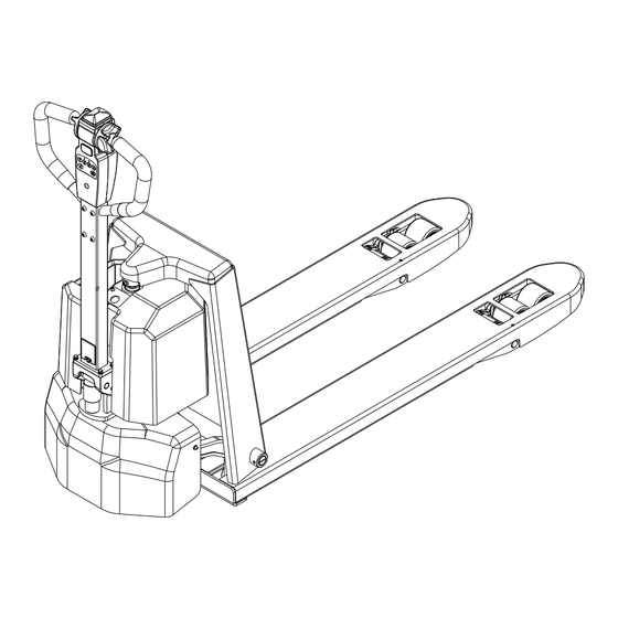
2.3 Main part introduction Item Description Item Description Control handle Drive wheel cover Control lever Left hood Lift cylinder Wire fixator Emergency stop switch Load wheel Right hood Fork... -
Page 12: Display And Control
2.4 Display and control Item Description Item Description Belly switch Horn Forward and backward switch Fork down button password keyboard Fork lifting button Electricity meter Electricity meter display function Power display: ten levels display the percentage of remaining power; Power shortage reminder: flashing reminder when there is 15% remaining power, the frequency is 1 time/second;... - Page 13 Password lock function introduction: 1, 2, 3, 4 are the password setting keys, which can be used repeatedly, the password is 4 digits, and 16 groups of startup passwords can be set; Two red and green LED indicators. Password lock function code description ...
- Page 14 6) To exit the current function operation, press the cancel button, the red indicator light flashes twice; Warning: User password cannot be repeated; Delete a user 1) When the vehicle is powered off, enter the administrator password and press "OK", the red indicator light keeps flashing;...
-
Page 15: Standard Technical Data
2.5 Standard technical data The following technical data are all standard data. Our company reserves the right of alteration and extension. CBD15-AMJ-SI Model CBD20-AMA-SI CBD15-AMA-SI Operator type Pedestrian Pedestrian Load capacity Q (kg) 1500 2000 Load center c(mm) Wheelbase y(mm) 1123①... -
Page 16: Product Plates And Warning Labels Location
2.6 Product plates and warning labels location Plates and labels, such as nameplate, load curve plate, warning labels must be legible, if identification is unclear, and must be replaced. The figure below shows the approximate location of the various identity resides. Before operating the truck, please understand the meaning of the various identities. -
Page 17: Safety Instructions
accident. Safety Instructions – Make sure change the “safety parts” Only trained and authorized operator during the schedule maintenance. shall be permitted to operate the truck. – Wipe off the oil, grease or water on the soleplate, foot pedal and control lever. –... - Page 18 going up and down the slope, please high position. organize staff to repair. 15) When handling bulky loads, which restrict your vision, please operate the machine in reverse or have a guide. 16) Cause the wheels of pallet truck is small, it is not allowed to run on the street, and only for driving in specified stacking place.
- Page 19 the slope. It’s prohibited to turn on the 24) Use tray when carrying small items, do slope, or there’s danger of tipping over. not place on the fork directly. Avoid working on the slope. 25) Do wash the inner of the truck, do not 20) Do not use truck under the weather of place the truck outdoors and exposed to sand, snow, thunder, storm, typhoon, etc.
-
Page 20: Transport
Transport The forklift truck is designed for short-distance lifting,lowering and transporting load units, not suitable for long-distance travel. If needed, the forklift truck must be transported by using lifting device or platform to place on truck or trailer. 4.1 Lifting by crane WARNING ... -
Page 21: Securing The Truck During Transport
4.2 Securing the truck during transport Correctly fix the forklift truck to avoid move when using truck or trailer. Procedure: – Park the truck securely. – Sling the tensioning belt around the truck and attach it to the fastening rings of the transporting vehicle. -
Page 22: Transport
4.3 Transport The pallet truck is designed for short-distance material handling only and is inappropriate for long-distance transportation. If needed, the truck must be transported by using lifting device or platform to place it on truck or trailer. Before operation, fix the pallet truck firmly on the transport vehicle with belt, and block the wheel to avoid relative motion during transportation. -
Page 23: Battery And Charger
Battery and charger Battery The 1.5T truck comes standard with a 24V/25Ah (2.0T 48V/20Ah)lithium battery pack, lithium battery pack weighs about 5kg. When the battery temperature reaches 25℃~30℃, its service life is the longest. Lower temperature reduces battery available capacity and higher temperature shortens battery service life. -
Page 24: Safe Operation Rules For Battery Use
5.1 Safe operation rules for battery use – Please charge the battery at an ambient temperature of 0℃ to 40℃. – Do not decompose the battery in any way! – Please prevent the battery from water or infiltration of any corrosive liquid. –... -
Page 25: Battery Charging
5.2 Battery charging That is, during truck operation the battery discharge process, the battery over-discharge is prohibited. After the truck is running, it is timely to charge the battery. WARNING You must use the original charger provided by our company to charge the battery. Before the battery is full, try not to interrupt the charging process. -
Page 26: New Truck Breaking-In
New truck breaking-in We recommended operating the truck under light load conditions for the first stage of operation to get the most from it. Especially the requirements given below should be observed while the truck is in a stage of 100 hours of operation: –... -
Page 27: Operation
the scales. Add oil when insufficient. Operation Battery check 7.1 Check before operation Check the battery cover board. See whether In order for the safety truck operation and the battery fixed reliably. keep the truck in good condition, before Check the terminal for loose or damage. starting the truck, you must check it carefully. - Page 28 12) Horn Press the horn button to check sound. 13) Appearance Check the truck appearance for clean, rust or paint spalling. 14) Others Check whether there is any abnormal noise, whether wiring is regular or fastener loosens etc.
-
Page 29: Start Up
7.2 Start up Procedure: – Carry out check before operation and make sure each function and state is normal. – Pull up the emergency stop switch (4). – Enter the correct password at the handle password keyboard (12) and press the OK button. Truck goes into running state. -
Page 30: Travelling
7.3 Travelling Driver should walk in front of the truck and keep at the side front of the truck when travelling. One hand holds the handle, and operates travel switch with thumb. Always watch moving direction and guide the truck. Or hold the handle with both hands and push the truck go forward. CAUTION ... -
Page 31: Braking
Slow down Slowly loosen the thumb, the direction speed control button will return automatically and the truck slows down. 7.4 Braking When the thumb off the direction speed control button, pull the handle to braking range (B1 or B2) position or vertical position, the truck brakes. CAUTION ... -
Page 32: Loading
7.7 Loading Procedure: – Drive the truck carefully up to the loads. – Adjust fork height to make the forks are in the tray. – Raise the loads several centimeters to make sure if the loads are firm. – Travel the truck off the area. –... - Page 33 – Drop down the forks to proper position.
-
Page 34: Park The Truck Securely
7.9 Park the truck securely Procedure: – Drive the truck to safe area or appointed area. – Fully lower the forks. – Press the emergency stop switch (4). -
Page 35: Deposit The Truck For Long Time
Deposit the truck for long time 8.1 Deposit for long time – Fully check the truck, especially check the wheel damage. – Check fluid oil for leakage. – Apply lubrication grease. – Check the joint face of cylinder piston rod for looseness, and if scratch on the piston rod surface. -
Page 36: Maintenance
Inspection and maintenance are usually ignored, you’d better find out the problems early and solve it in time. – Use authentic parts of Hangcha Group. – Don’t use different oil when changing or adding oil. Don’t rave about oil and electrolyte used at will, and carry on handling according to the local environmental protection laws and regulations. -
Page 37: Periodic Maintenance Schedule
9.2 Periodic maintenance schedule The service intervals stated are based on single shift operation under normal operating conditions. They must be reduced accordingly if the truck is to be used in conditions of extreme dust, temperature fluctuations or multiple shifts. The following servicing checklist indicates the operations to be performed and the respective intervals to be observed. - Page 38 Steering ● Test electric steering and its components. ● Check tiller recuperating function. ● Bearing lubrication Electrical system Test warning and safety devices in accordance with operating ● instructions ● Test the displays and controls. ● Check the function of micro switch and sensor. ●...
-
Page 39: Removal And Installation Of The Right Hood Wheel Cover
9.3 Removal and installation of the right hood wheel cover Procedure: – Park the truck securely. – Unscrew the screw fixing the right hood. – Remove the right hood to the right. – Unscrew the screws fixing the wheel cover –... -
Page 40: Truck Used Oil And Lubrication
Truck used oil and lubrication Filler plug for hydraulic oil Gliding surfaces Code Designation Mark, code Remark Normally:L-HM32 Hydraulic oil Hydraulic system High and cold environment:L-HV32 Grease Automobile general 3 # lithium base lubricant Nozzle and lubrication CAUTION Into the fuel tank of hydraulic oil must be filtered, and the injection volume of the hydraulic oil tank does not exceed the maximum scale. -
Page 41: Replace Wheels
driving wheels from the drive unit. Replace wheels Procedure: – Dismantle the drive unit from the truck. CAUTION Strike the edge of the driving wheels – Remove the 12 socket hexagon screws evenly and symmetrically. which is used to fix the driving wheels ... -
Page 42: Relevant Safety Directive Or Standard (Ce)
Relevant safety directive or standard (CE) After CE certificated, the truck meets the following directive and standard: – 2006/42/EC machinery directive(namely Directive of the council of the laws of the member states concerning machinery ) , 2000/14/EC Noise Directive (Namely Directive of the council of the laws of the member states concerning noise radiation of outdoor equipment);... -
Page 43: Part Ⅱ:structure, Principle And Maintenance
Part Ⅱ:Structure, Principle and Maintenance Drive Unit 1.1 Data sheet Speed ratio of reduction gear box 24.6857 Max. wheel torque N•m Max. wheel load 1000 Rated voltage Rated power Rated current Rated speed r/min 3300 Drive motor Working system S2=45min Insulation grade Protection grade IP44... -
Page 44: Assemble And Use Notice
1.2 Assemble and use notice – When assemble, scrub the oil seal on the product. Avoid product damage, no disassemble at will. – Avoid each fitting surface and exposed gear impact, thus influence installation. – Normal working oil temperature is ≤70℃. –... -
Page 45: Drive Motor
1.4 Drive Motor Wiring Diagram of Motor 24VDC Black 24VDC Black Motor use notice – Keep clean and dry around the motor, and do no place other objects on or in the motor. – Do not use with overload. – Never coexist with strong magnetic object. - Page 46 cloth, when there is grease on the surface, immerse the cloth in alcohol to wipe(park). – Check if all fasteners are tight. – Brush carrier should be fastening and no loose. If turn or remove the brush carrier needed, only mark can loosen the end cap bolt. Aim at marker line to tighten screw when brush carrier reset to keep the brush in neutral position.
- Page 47 – After polishing crocus cloth and cleaning commutator, motor should work under limited speed to ensure safety until the brush working surface polishes.
- Page 48 Fault diagnosis Probable cause Fault All copper sheet blacken Pressure of the brush is not right ·Short circuit of commutator segments Commutator segments blacken in ·Short circuit of armature coils group according to certain sequence ·The welding of commutator segments and armature coils is not good or short circuit.
-
Page 49: Electromagnetic Brake
1.5 Electromagnetic brake The spring-loaded electromagnetic brake is applied in the truck which is a single disk brake with double friction surfaces. By use of the pressure spring, powerful braking torque would be generated when power off. The brake could be released by the electromagnetic effect. 1.Mounting Bolt of the Brake 2.Stator Module 3.Brake Pad... -
Page 50: Electromagnetic Brake Working Principle
1.5.1 Electromagnetic brake working principle Motor shaft (9) is connected with shaft sleeve (4) by passing through the flat key. And shaft sleeve (4) is connected with brake pad (3) by passing through the splines. When the stator (11) is block out, the force produced by the pressure spring (10) would act on the armature (8) which makes rotated the brake pad (3) driven by the motor shaft connected closely between the armature (8) and cover plate (5). -
Page 51: Electromagnetic Brake Installation
1.5.2 Electromagnetic brake installation – Put the flat key (13) into the key groove of the motor shaft (9). Press the shaft sleeve (4) to the motor shaft (9) and fasten it with the inner spring. – Install the friction disk (5) to the end face of the motor by using three mounting bolts of the friction bolts (12). -
Page 52: Maintenance
WARNING No broken wire sheath, or else the circuit might be damaged. Do not process the locating surface or the holes of the production without authorization, or else the magnet loop would be influenced. Do not over press when fitting the motor shaft. Make sure no damage on the friction surface and wipe off the burr of the mounting holes and surfaces. -
Page 53: Adjust The Air Gap Of The Brake
1.5.4 Adjust the Air Gap of the Brake Rated air gap Z grows with the friction. In order to there is sufficient braking torque, the air gap must be set before it reaches to the maximum value. The air gap can be adjusted by several times. When the thickness of brake pad becomes the minimum value(see the specification table below), the brake pad must be replaced. - Page 54 Under the general operating conditions, the first set of the air gap is usually after 1500 to 2000 hours service of the brake and it is suggested to adjust the air gap every 6 months. If it comes to a poor working condition, such as frequent use of brake and repeated emergency stops,the air gap should be set when the brake the shorten the adjustment interval for the first time.
-
Page 55: Common Fault And Troubleshooting
1.5.5 Common fault and troubleshooting Fault Probable cause Corrective action Power is obstructed Connect Too low exciting voltage Check voltage and adjust. Brake does not Improper air gap Adjust air gap work Stator coil breaks Replace stator Oil dirt mixed in Clean oil dirt Install the switch to the DC circuit Switch installed to AC circuit... -
Page 56: Schematic Diagram Of Braking
1.5.6 Schematic diagram of braking The forklift truck motor is equipped with an electromagnetic brake. When the forklift is parked, the electromagnetic brake is released. The brake pads firmly lock the motor shaft and the forklift is in a mechanical braking state. battery Traction motor Brake switch... -
Page 57: Hydraulic System
Hydraulic system 2.1 Hydraulic system working principle... -
Page 58: Hydraulic System Fault Diagnosis And Correction
2.2 Hydraulic system fault diagnosis and correction Fault Probable cause Corrective action Low oil level Fill to the specified oil level No oil pumps Clean oil pipe and oil tank. If hydraulic oil is from the pump Blocking of strainer dirty, please change it. -
Page 59: Electric System
Electric system 3.1 Electrical schematic diagram CBD15-AMJ-SI... - Page 60 CBD15-AMA-SI、 CBD20-AMA-SI...
- Page 61 CBD15-AMJ2-SI...
-
Page 62: Drive Motor Controller
3.2 Drive motor controller 3.2.1 Maintenance Controller has no user repair parts. Do not try to open, repair or alter the controller. Otherwise it may damage the controller and also invalid the guarantee. It’s suggested to keep the controller clean and dry, periodically check and get rid of diagnose historical files. - Page 63 3.2.2 Diagnostics and Troubleshooting CBD15/20-AMA-SI(D) error code B.1 Description of the fault indicator of the controller. The controller status indicator is displayed by blue and red LED lights. The flashing time of the indicator is different in the normal state and the fault state. In the normal state, only the blue light flashes for 1 second.
- Page 64 Emergency reverse touch error Positive and negative switch error Speeding error EEPROM abnormal Travel error while charging Current sampling is damaged Deceleration timeout error Accelerator push to trigger emergency reverse -> emergency stop Motor temperature sensor open circuit Motor temperature sensor short circuit IGBT temperature sensor open circuit IGBT temperature sensor short circuit IU phase software overcurrent...
- Page 65 1. The temperature of the bottom plate is too high. 2. The motor is overloaded. Temperature failure 3. The ambient temperature is too high or too low. 4. The electromagnetic brake is released. 1. The accelerator wiper is disconnected. Accelerator failure 2.
- Page 66 1. M2 bridge arm failure MOSFET is M2 bridge arm failure damaged.
- Page 67 1212E FAULTS When the controller detects a fault, the controller operates in a manner that is safe in the presence of that fault. Depending on the severity of the fault, the controller’s response can range from reducing current to shutting down the vehicle. Some faults are set by multiple conditions.
- Page 68 Defective temperature sensor controller Lower controller Shut down throttle temperature is at least temperature to under the Controller 15°C higher than the temperature cutback point. Severe temperature cutback point Overtemp for 48ms. 0x2142...
- Page 69 FLASH CODE FAULT NAME TYPE SET CONDITION CLEAR CONDITION FAULT ACTIONS POSSIBLE CAUSES CAN INDEX • Throttle wiring fault The throttle AD data is out Cycle the keyswitch. Shut down throttle of range for 48ms. • Incorrect throttle type setting Throttle Fault •...
- Page 70 FLASH CODE FAULT NAME TYPE SET CONDITION CLEAR CONDITION FAULT ACTIONS POSSIBLE CAUSES CAN INDEX • Defective motor The armature current is Cycle the keyswitch. Shut down motor greater than 90% of the Shut down main • Defective controller Stall Detected current limit and the motor contactor 0x2231...
- Page 71 FLASH CODE FAULT NAME TYPE SET CONDITION CLEAR CONDITION FAULT ACTIONS POSSIBLE CAUSES CAN INDEX The motor speed is greater than the ramped speed curve for more than 80ms during interlock braking. The motor speed is greater than the ramped speed curve for more than 80ms while the vehicle decelerating...
- Page 72 FLASH CODE FAULT NAME TYPE SET CONDITION CLEAR CONDITION FAULT ACTIONS POSSIBLE CAUSES CAN INDEX • Incorrect operation sequence The lift input is active Cycle the keyswitch. Shut down lift when the keyswitch is • Defective switch Pump turned on. Fault The lower input is active Cycle the keyswitch.
- Page 73 FLASH CODE FAULT NAME TYPE SET CONDITION CLEAR CONDITION FAULT ACTIONS POSSIBLE CAUSES CAN INDEX CANbus is overloaded. During the operational Cycle the keyswitch Shut down throttle NMT state, RPDO1 did or send an NMT reset Clear related data PDO Timeout not receive a message command.
- Page 74 FLASH CODE FAULT NAME TYPE SET CONDITION CLEAR CONDITION FAULT ACTIONS POSSIBLE CAUSES CAN INDEX • Invalid parametervalue A parameter marked as Cycle the keyswitch. Shut down motor [PCF] in the Programming Shut down main • Defective FRAM Parameter Menu Parameters chapter contactor Fault was set but the keyswitch...
- Page 75 FLASH CODE FAULT NAME TYPE SET CONDITION CLEAR CONDITION FAULT ACTIONS POSSIBLE CAUSES CAN INDEX The Pot Hi Switch Function Cycle the keyswitch. parameter specifies value other than Pot Hi Input but the Throttle Type parameter specifies a 3-wire pot throttle. The Inching Input Source Cycle the keyswitch.
- Page 76 The following table lists the fault types for the Supervision fault. Table 7-2 Supervisor Fault Types Fault Type Fault Type Variable SUPERVISOR_FIFTEEN_V_SUPPLY_FAILURE SUPERVISOR_HARDWARE_FAULT PRIMARY_INIT_CAN_OBJ PRIMARY_INIT_ILLEGAL_CAN_SIZE PRIMARY_INIT_CAN_SIZE PRIMARY_INIT_TIMEOUT PRIMARY_WRITE_OBJECT PRIMARY_WRITE_SIZE PRIMARY_WRITE_TIMEOUT PRIMARY_WRITE_CRC PRIMARY_WRITE_ACK...
-
Page 77: Diagnostics And Troubleshooting
Attachment:Table for bolt’s tightening torque If not specified, select the tightening torque from the below table: Unit :N·m Grade Bolt’s diameter 4~5 5~7 6~8 9~12 10~12 12~15 14~18 22~29 20~25 25~31 29~39 44~58 35~44 44~54 49~64 76~107 54~69 69~88 83~98 121~162 88~108 108~137... -
Page 78: Maintenance Record
Maintenance Record Date Repair, maintenance content Serviceman... - Page 79 HANGCHA GROUP CO. , LTD. ■ Address: 666 Xiangfu Road, Hangzhou, Zhejiang, China ■ Fax: 0086-571-88926789 0086-571-88132890 ■ ZIP:311305 ■ Web: http://www.hcforklift.com ■ E-mail: sales@hcforklift.com...
Need help?
Do you have a question about the CBD15-AMA-SI and is the answer not in the manual?
Questions and answers