Page 1
Mini Range CBD15-A2MC1 
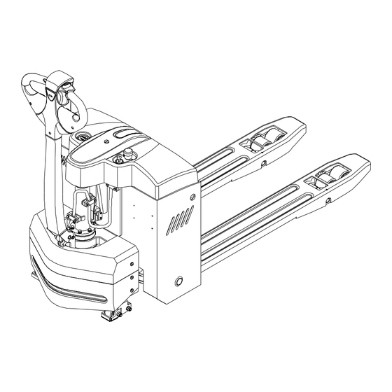
ELECTRIC PALLET TRUCK CBD15-A3MC1 CBD15-A3MC2 CBD15-A3MC1-I CBD15-A3MC2-I OPERATION AND MAINTENANCE MANUAL Original Instruction HANGCHA GROUP CO., LTD. 11/2022...
Page 2
FOREWORD Thank you very much for purchasing the A series mini range electric pallet truck of Hangcha Group . A series mini range electric pallet truck is a newly developed product for warehouse logistic, it owns characteristics as advanced performance, comfort operation, safety and security, low maintenance cost, and is an ideal tool for handling goods in warehouse, supermarket and workshop.
Contents Part Ⅰ:Operation and Maintenance .................... 1 Notice for use ..........................1 1.1 General ............................1 1.2 Use as required ......................... 1 1.3 Approved application conditions ....................2 1.4 Attachment installation or modification to the truck ..............3 Truck introduction ........................4 2.1 General ............................
Page 4
9.6 Check the fuses ........................40 9.7 Replace wheels ........................41 Relevant safety directive or standard (CE) ................42 Part Ⅱ:Structure, Principle and Maintenance ................43 1 Drive Unit ............................43 1.1 Data sheet ..........................43 1.2 Assemble and use notice ......................44 1.3 Fault and troubleshooting ......................44 1.4 Drive Motor ..........................
Part Ⅰ:Operation and Maintenance Notice for use 1.1 General Truck in this manual is only for lifting and transporting loads. This truck is not designed for heavy-duty. It must be used, operated and maintained according to the information in this manual. Any other uses are outside the design envelope and can lead to injury to persons or damage to equipment and property.
1.3 Approved application conditions - Used in specified area as factory, tourist attraction and recreation place. - Operation only on secure, level surfaces with sufficient capacity. - Operation only on routes that are visible and approved by the proprietor. - Use in specified rated load. -...
1.4 Attachment installation or modification to the truck Without authorization by the manufacturer, it is not allowed to modify the truck privately. The mounting or installation of any attachments which will interfere with, or supplement, the functions of the truck is permitted only after written approval by the manufacturer has been obtained.
Truck introduction 2.1 General A series mini range electric pallet truck described in this manual should work under low working strength and its continuous working time should not surpass one hour. Users can get relevant information as rated load from the product model. CBD15-A3MC1-I Meaning Electric pallet truck...
2.2 Functional description Frame – Beautiful and compact outline, concise and fluent line. – Adopted steel stamping and injection moulding process is sturdy and durable. Driving system – Drive unit adopts wheel type, with compact and simple structure. – Permanent-magnetic drive motor owns excellent performance. –...
Page 10
━ Three braking system of regenerative braking, reverse current braking, parking brake, insures the safe operation. ━ Anti-slope on gradient can keep the safety. ━ The emergency button on the tiller head can effectively avoid the harm to the driver. ━...
2.4 Display and control Item Designation Function Control lever Control the steering and brake of the truck. Normally on normal condition. Failure regularity, see Fault indicator the failure code. Display the Battery charge level indicator and the Display(battery charge level indicator) truck total work hour indicator Cut the connection with the battery, close all electric...
2.4.1 Display (battery charge level indicator) Display the Battery charge level indicator and the truck total work hour indicator 3.Battery power icon 1.power of the battery 4.Shows the data is exchanged between display 1.2h ¤ ¤¤¤¤ and battery 2.Error code Hour meter Battery charge level indicator(1)(3)...
Page 14
Error code(2) The fault code is displayed in the lower left corner of the instrument, which can be compared according to the Troubleshooting Chart below. Hour meter(5) This meter indicates the actual usage time of the truck, thus enabling the correct maintenance to be performed according to the set schedule.
2.5 Standard technical data The following technical data are all standard data. Our company reserves the right of alteration and extension. CBD15-A2MC1 CBD15-A3MC1-I Model CBD15-A3MC1 CBD15-A3MC2-I CBD15-A3MC2 Operator type Pedestrian Pedestrian Load capacity Q (kg) 1500 1500 Load center c(mm) Weight Service weight with battery Tyres type Tyre size, front...
2.6 Product plates and warning labels location Plates and labels, such as nameplate, load curve plate, warning labels must be legible, if identification is unclear, and must be replaced. The figure below shows the approximate location of the various identity resides. Before operating the truck, please understand the meaning of the various identities.
Page 17
Item Description Nameplate: The rated capacity on the nameplate is the max. load capacity by the label listed equipment. Any change to the forklift or other equipment may change rated capacity. Fault indicator Charging light indicator. Overnight charging recommend after use ! Manufacturer’s logo Hoist label: Strap points for crane lifting.
accident. Safety Instructions – Make sure change the “safety parts” Only trained and authorized operator during the schedule maintenance. shall be permitted to operate the truck. – Wipe off the oil, grease or water on the soleplate, foot pedal and control lever. –...
Page 19
going up and down the slope, please 15) When handling bulky loads, which organize staff to repair. restrict your vision, please operate the machine in reverse or have a guide. 16) Cause the wheels of pallet truck is small, it is not allowed to run on the street, and only for driving in specified stacking place.
Page 20
slope, or there’s danger of tipping over. not place on the fork directly. Avoid working on the slope. 25) Do wash the inner of the truck, do not 20) Do not use truck under the weather of place the truck outdoors and exposed to sand, snow, thunder, storm, typhoon, etc.
Transport The forklift truck is designed for short-distance lifting,lowering and transporting load units, not suitable for long-distance travel. If needed, the forklift truck must be transported by using lifting device or platform to place on truck or trailer. 4.1 Lifting by crane WARNING ...
4.2 Securing the truck during transport Correctly fix the forklift truck to avoid move when using truck or trailer. Procedure: – Park the truck securely. – Sling the tensioning belt around the truck and attach it to the fastening rings of the transporting vehicle.
4.3 Transport The pallet truck is designed for short-distance material handling only and is inappropriate for long-distance transportation. If needed, the truck must be transported by using lifting device or platform to place it on truck or trailer. Before operation, fix the pallet truck firmly on the transport vehicle with belt, and block the wheel to avoid relative motion during transportation.
Battery and charger Battery The 1.5T truck comes standard with a 24V/40Ah lithium battery pack, lithium battery pack weighs about 5kg. When the battery temperature reaches 25 ℃ ~ 30 ℃ , its service life is the longest. Lower temperature reduces battery available capacity and higher temperature shortens battery service life.
5.1 Safe operation rules for battery use – Please charge the battery at an ambient temperature of 0℃ to 40℃. – Do not decompose the battery in any way! – Please prevent the battery from water or infiltration of any corrosive liquid. –...
5.2 Battery charging That is, during truck operation the battery discharge process, the battery over-discharge is prohibited. After the truck is running, it is timely to charge the battery. WARNING You must use the original charger provided by our company to charge the battery. Before the battery is full, try not to interrupt the charging process.
Page 27
At the same time, the charging cable can be inserted into the reserved charging port for charging without removing the lithium battery.
New truck breaking-in We recommended operating the truck under light load conditions for the first stage of operation to get the most from it. Especially the requirements given below should be observed while the truck is in a stage of 100 hours of operation: –...
the scales. Add oil when insufficient. Operation 7.1 Check before operation In order for the safety truck operation and keep the truck in good condition, before starting the truck, you must check it carefully. Oil leak and liquid leak check Park the truck and check oil leakage.
Page 30
running condition; gradually press accelerator button to the inside of the body with thumb, and inspect the reverse running condition. 10) Brake system When the truck run forward or backward, push the handle to vertical position or press to level position to check the brake condition. 11) Steering system Left or right turn the handle to make the truck run around 3 turns, and then check if the...
7.2 Start up Procedure: – Carry out check before operation and make sure each function and state is normal. – Pull up the emergency stop switch (16). – Plug the key into key switch (17), turn to “ON” position in clockwise. The instrument displays battery capacity.
7.3 Travelling Driver should walk in front of the truck and keep at the side front of the truck when travelling. One hand holds the handle, and operates travel switch with thumb. Always watch moving direction and guide the truck. Or hold the handle with both hands and push the truck go forward. CAUTION ...
Slow down Slowly loosen the thumb, the direction speed control button will return automatically and the truck slows down. Rear Rear Forward Forward 7.4 Braking When the thumb off the direction speed control button, pull the handle to braking range (B1 or B2) position or vertical position, the truck brakes.
– Drop the fork to the lowest position. – Turn off the switch to “OFF” position, press down the emergency disconnect switch, pull out the battery plug, and take off the key. – Fold up 7.7 Loading Procedure: – Drive the truck carefully up to the loads. –...
Page 35
– Travel backward and make the fork out of the load. – Drop down the forks to proper position.
7.9 Park the truck securely Procedure: – Drive the truck to safe area or appointed area. – Fully lower the forks. – Turn off the key switch (17), and remove the key. – Press the emergency stop switch (16).
Deposit the truck for long time 8.1 Deposit for long time – Fully check the truck, especially check the wheel damage. – Check fluid oil for leakage. – Apply lubrication grease. – Check the joint face of cylinder piston rod for looseness, and if scratch on the piston rod surface.
Inspection and maintenance are usually ignored, you’d better find out the problems early and solve it in time. – Use authentic parts of Hangcha Group. – Don’t use different oil when changing or adding oil. Don’t rave about oil and electrolyte used at will, and carry on handling according to the local environmental protection laws and regulations.
9.2 Periodic maintenance schedule The service intervals stated are based on single shift operation under normal operating conditions. They must be reduced accordingly if the truck is to be used in conditions of extreme dust, temperature fluctuations or multiple shifts. The following servicing checklist indicates the operations to be performed and the respective intervals to be observed.
Page 40
Steering ● Test electric steering and its components. ● Check tiller recuperating function. ● Bearing lubrication Electrical system Test warning and safety devices in accordance with operating ● instructions ● Test the displays and controls. ● Check the function of micro switch and sensor. ●...
9.3 Remove or installing the hood Remove the hood Procedure: – Park the truck securely. – Unscrew the hood screws (41). – Lift the hood (15). – The wire fixate (12) from the hood (15) to take off on. The hood is removed. Installation and removal process is reversed. WARNING ...
9.4 Remove or installing the drive wheel cover Remove the drive wheel cover Procedure: – Unscrew the drive wheel cover (4) of the four screws (40), remove the drive wheel cover. The drive wheel cover is removed. Installation and removal process is reversed. WARNING ...
9.5 Truck used oil and lubrication Filler plug for hydraulic oil Gliding surfaces Code Designation Mark, code Remark Normally:L-HM32 Hydraulic oil Hydraulic system High and cold environment:L-HV32 Grease Automobile general 3 # lithium base lubricant Nozzle and lubrication CAUTION Into the fuel tank of hydraulic oil must be filtered, and the injection volume of the hydraulic oil tank does not exceed the maximum scale.
9.6 Check the fuses Procedure: ━ Maintenance work to complete preparations before the operation. ━ Remove the hood. ━ Check the fuse (42,43) values are correct, if necessary, replace. Designation Control circuit Specification Fuse Pump motor Fuse Controller...
driving wheels from the drive unit. 9.7 Replace wheels Procedure: – Dismantle the drive unit from the truck. CAUTION Strike the edge of the driving wheels – Remove the 12 socket hexagon screws evenly and symmetrically. which is used to fix the driving wheels ...
Relevant safety directive or standard (CE) After CE certificated, the truck meets the following directive and standard: – 2006/42/EC machinery directive(namely Directive of the council of the laws of the member states concerning machinery ) , 2000/14/EC Noise Directive (Namely Directive of the council of the laws of the member states concerning noise radiation of outdoor equipment);...
Part Ⅱ:Structure, Principle and Maintenance Drive Unit 1.1 Data sheet Speed ratio of reduction gear box 24.6857 Max. wheel torque N•m Max. wheel load 1000 Rated voltage Rated power Rated current Rated speed r/min 3300 Drive motor Working system S2=45min Insulation grade Protection grade IP44...
1.2 Assemble and use notice – When assemble, scrub the oil seal on the product. Avoid product damage, no disassemble at will. – Avoid each fitting surface and exposed gear impact, thus influence installation. – Normal working oil temperature is ≤70℃. –...
1.4 Drive Motor Wiring Diagram of Motor 24VDC Black 24VDC Black Motor use notice – Keep clean and dry around the motor, and do no place other objects on or in the motor. – Do not use with overload. – Never coexist with strong magnetic object.
Page 50
cloth, when there is grease on the surface, immerse the cloth in alcohol to wipe(park). – Check if all fasteners are tight. – Brush carrier should be fastening and no loose. If turn or remove the brush carrier needed, only mark can loosen the end cap bolt. Aim at marker line to tighten screw when brush carrier reset to keep the brush in neutral position.
Page 51
– After polishing crocus cloth and cleaning commutator, motor should work under limited speed to ensure safety until the brush working surface polishes.
Page 52
Fault diagnosis Probable cause Fault All copper sheet blacken Pressure of the brush is not right ·Short circuit of commutator segments Commutator segments blacken in ·Short circuit of armature coils group according to certain sequence ·The welding of commutator segments and armature coils is not good or short circuit.
1.5 Electromagnetic brake The spring-loaded electromagnetic brake is applied in the truck which is a single disk brake with double friction surfaces. By use of the pressure spring, powerful braking torque would be generated when power off. The brake could be released by the electromagnetic effect. 1.Mounting Bolt of the Brake 2.Stator Module 3.Brake Pad...
1.5.1 Electromagnetic brake working principle Motor shaft (9) is connected with shaft sleeve (4) by passing through the flat key. And shaft sleeve (4) is connected with brake pad (3) by passing through the splines. When the stator (11) is block out, the force produced by the pressure spring (10) would act on the armature (8) which makes rotated the brake pad (3) driven by the motor shaft connected closely between the armature (8) and cover plate (5).
1.5.2 Electromagnetic brake installation – Put the flat key (13) into the key groove of the motor shaft (9). Press the shaft sleeve (4) to the motor shaft (9) and fasten it with the inner spring. – Install the friction disk (5) to the end face of the motor by using three mounting bolts of the friction bolts (12).
WARNING No broken wire sheath, or else the circuit might be damaged. Do not process the locating surface or the holes of the production without authorization, or else the magnet loop would be influenced. Do not over press when fitting the motor shaft. Make sure no damage on the friction surface and wipe off the burr of the mounting holes and surfaces.
1.5.4 Adjust the Air Gap of the Brake Rated air gap Z grows with the friction. In order to there is sufficient braking torque, the air gap must be set before it reaches to the maximum value. The air gap can be adjusted by several times. When the thickness of brake pad becomes the minimum value(see the specification table below), the brake pad must be replaced.
Page 58
Under the general operating conditions, the first set of the air gap is usually after 1500 to 2000 hours service of the brake and it is suggested to adjust the air gap every 6 months. If it comes to a poor working condition, such as frequent use of brake and repeated emergency stops,the air gap should be set when the brake the shorten the adjustment interval for the first time.
1.5.5 Common fault and troubleshooting Fault Probable cause Corrective action Power is obstructed Connect Too low exciting voltage Check voltage and adjust. Brake does not Improper air gap Adjust air gap work Stator coil breaks Replace stator Oil dirt mixed in Clean oil dirt Install the switch to the DC circuit Switch installed to AC circuit...
2.2 Hydraulic system fault diagnosis and correction Fault Probable cause Corrective action Low oil level Fill to the specified oil level No oil pumps Clean oil pipe and oil tank. If hydraulic oil is from the pump Blocking of strainer dirty, please change it.
3.2 Drive motor controller 3.2.1 Maintenance Controller has no user repair parts. Do not try to open, repair or alter the controller. Otherwise it may damage the controller and also invalid the guarantee. It’s suggested to keep the controller clean and dry, periodically check and get rid of diagnose historical files.
Page 68
3.2.2 Diagnostics and Troubleshooting When faults happen, try to restart by resetting the key switch after confirmed that faults are not caused by faulty wiring connection or mechanical failure. If the faults are still on, shut down the key, check for incorrect connection or corruption of the pin 35 connecter, reconnect after repaired and cleared, and then restart again.
Page 69
Troubleshooting Chart Led Codes Fault indicator status Fault Possible Cause no power or defective controller controller powered up; No faults 1)Temperature >8℃C or < -10℃. 2)Battery contact bad.. ¤ ¤ Thermal Fault 3)Work under extreme severe environment. 4)Electromagnetic brake does not release normally. 1)Throttle input wire open or shorted.
Page 70
1212E FAULTS When the controller detects a fault, the controller operates in a manner that is safe in the presence of that fault. Depending on the severity of the fault, the controller’s response can range from reducing current to shutting down the vehicle. Some faults are set by multiple conditions.
Page 71
Defective temperature sensor controller Lower controller Shut down throttle temperature is at least temperature to under the Controller 15°C higher than the temperature cutback point. Severe temperature cutback point Overtemp for 48ms. 0x2142...
Page 72
FLASH CODE FAULT NAME TYPE SET CONDITION CLEAR CONDITION FAULT ACTIONS POSSIBLE CAUSES CAN INDEX • Throttle wiring fault The throttle AD data is out Cycle the keyswitch. Shut down throttle of range for 48ms. • Incorrect throttle type setting Throttle Fault •...
Page 73
FLASH CODE FAULT NAME TYPE SET CONDITION CLEAR CONDITION FAULT ACTIONS POSSIBLE CAUSES CAN INDEX • Defective motor The armature current is Cycle the keyswitch. Shut down motor greater than 90% of the Shut down main • Defective controller Stall Detected current limit and the motor contactor 0x2231...
Page 74
FLASH CODE FAULT NAME TYPE SET CONDITION CLEAR CONDITION FAULT ACTIONS POSSIBLE CAUSES CAN INDEX The motor speed is greater than the ramped speed curve for more than 80ms during interlock braking. The motor speed is greater than the ramped speed curve for more than 80ms while the vehicle decelerating...
Page 75
FLASH CODE FAULT NAME TYPE SET CONDITION CLEAR CONDITION FAULT ACTIONS POSSIBLE CAUSES CAN INDEX • Incorrect operation sequence The lift input is active Cycle the keyswitch. Shut down lift when the keyswitch is • Defective switch Pump turned on. Fault The lower input is active Cycle the keyswitch.
Page 76
FLASH CODE FAULT NAME TYPE SET CONDITION CLEAR CONDITION FAULT ACTIONS POSSIBLE CAUSES CAN INDEX CANbus is overloaded. During the operational Cycle the keyswitch Shut down throttle NMT state, RPDO1 did or send an NMT reset Clear related data PDO Timeout not receive a message command.
FLASH CODE FAULT NAME TYPE SET CONDITION CLEAR CONDITION FAULT ACTIONS POSSIBLE CAUSES CAN INDEX • Invalid parametervalue A parameter marked as Cycle the keyswitch. Shut down motor [PCF] in the Programming Shut down main • Defective FRAM Parameter Menu Parameters chapter contactor Fault was set but the keyswitch...
Page 78
FLASH CODE FAULT NAME TYPE SET CONDITION CLEAR CONDITION FAULT ACTIONS POSSIBLE CAUSES CAN INDEX The Pot Hi Switch Function Cycle the keyswitch. parameter specifies value other than Pot Hi Input but the Throttle Type parameter specifies a 3-wire pot throttle. The Inching Input Source Cycle the keyswitch.
Need help?
Do you have a question about the Mini CBD15-A3MC1 and is the answer not in the manual?
Questions and answers