Sign In
Upload
Download
Table of Contents
Contents
Add to my manuals
Delete from my manuals
Share
URL of this page:
HTML Link:
Bookmark this page
Add
Manual will be automatically added to "My Manuals"
Print this page
×
Bookmark added
×
Added to my manuals
Manuals
Brands
HANGCHA Manuals
Trucks
CBD20-AC1S
Operation and maintenance manual
HANGCHA CBD20-AC1S Operation And Maintenance Manual
Electric pallet truck
Hide thumbs
1
2
Table Of Contents
3
4
5
6
7
8
9
10
11
12
13
14
15
16
17
18
19
20
21
22
23
24
25
26
27
28
29
30
31
32
33
34
35
36
37
38
39
40
41
42
43
44
45
46
47
48
49
50
51
52
53
54
55
56
57
58
59
60
61
62
63
64
65
66
67
68
69
70
71
72
73
74
75
76
77
78
79
80
81
82
83
84
85
86
87
88
89
90
91
92
93
94
95
96
97
98
99
100
101
102
103
104
105
106
107
108
109
110
111
112
113
114
115
116
117
page
of
117
Go
/
117
Contents
Table of Contents
Troubleshooting
Bookmarks
Table of Contents
Table of Contents
Part : Operation and Maintenance
Truck Introduction
General
Use Occasion and Condition
Main Part Name
Display and Control
Display
Control
Others
Standard Technical Data
Product Plates and Warning Labels Location
Safety Rules
Transport
Lifting by Crane
Securing the Truck During Transport
How to Remove a Broken Truck
Battery
Attention for Using Battery
Dimension/Service Weight
Charging the Battery
Replacing the Battery
New Truck Breaking-In
Operation
Check before Operation
Start up
Travelling
Braking
Steering
Stopping
Loading
Unloading
Parking
Deposit the Truck for Long Time
Deposit for Long Time
Start Running after Deposit for a Long Time
Maintenance
Maintenance General
Periodic Maintenance Schedule
Truck Used Oil and Lubrication
Replace the Key Safe Parts Periodically
Screw down the Wheel Retaining Nut
Removing the Hood
Relevant Safety Directive or Standard (CE)
Part Structure, Principle and Maintenance
Drive System
Reduction Box
Working Principle
Dismount and Assemble Order
Notice to Installment and Use
Fault and Troubleshooting
Motor
Electromagnetic Brake
Working Principle
Brake Installment
Brake Air Gap Adjustment
Maintenance
Fault and Troubleshooting
Drive System Dismantle
Hydraulic System
Hydraulic System Working Principle
Hydraulic Unit
Hydraulic Unit Dismantle
Dismantle the Lifting Cylinder from the Truck or Replace
Hydraulic System Fault Diagnosis and Correction
Electric System
Principles of Electrical System
Controller
Maintenance
Diagnosis and Troubleshooting
1232 Controller Diagnosis and Troubleshooting
Attachment
Advertisement
Quick Links
1
Diagnosis and Troubleshooting
Download this manual
Hi Range
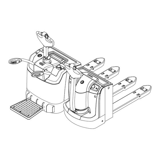
ELECTRIC PALLET TRUCK
CBD20/30-AC1S
CBD20/30-AZ3S
CBD20/30-AC1S-I
OPERATION AND MAINTENANCE MANUAL
Original Instruction
HANGCHA GROUP CO., LTD.
11/2019
Table of
Contents
Previous
Page
Next
Page
1
2
3
4
5
Advertisement
Table of Contents
Troubleshooting
Dismount and assemble order
70
Fault and troubleshooting
83
Diagnosis and troubleshooting
100
1232 Controller diagnosis and troubleshooting
102
Need help?
Do you have a question about the CBD20-AC1S and is the answer not in the manual?
Ask a question
Questions and answers
Related Manuals for HANGCHA CBD20-AC1S
Trucks HANGCHA Mini CBD15-A3MC1 Operation And Maintenance Manual
Electric pallet truck (82 pages)
Trucks HANGCHA CBD12-AMC1-I Operation And Maintenance Manual
Electric pallet truck (66 pages)
Trucks HANGCHA Mini Series Operation And Maintenance Manual
Electric pallet truck (66 pages)
Trucks HANGCHA CBD20-AEC1 Operation And Maintenance Manual
Electric pallet truck (96 pages)
Trucks HANGCHA XC Series Operation And Maintenance Manual
Electric reach truck (91 pages)
Trucks HANGCHA CBD20-AZ3S Operation And Maintenance Manual
Electric pallet truck (117 pages)
Trucks HANGCHA CBD15-WS Operations Manual & Parts List
Electric pallet truck (33 pages)
Trucks HANGCHA CBD15-A3MJ Operation And Maintenance Manual
Mini range electric pallet truck (81 pages)
Trucks HANGCHA Mini CBD15-A3MC2 Operation And Maintenance Manual
Electric pallet truck (82 pages)
Trucks HANGCHA Mini CBD15-A3MC2-I Operation And Maintenance Manual
Electric pallet truck (82 pages)
Trucks HANGCHA CBD15-AMA-SI Operation And Maintenance Manual
Electric pallet truck (79 pages)
Trucks HANGCHA CBD20-AMA-SI Operation And Maintenance Manual
Electric pallet truck (79 pages)
Trucks HANGCHA CBD15-AMC1-IRT Operation And Maintenance Manual
Off-road pallet truck (68 pages)
This manual is also suitable for:
Cbd30-ac1s
Cbd20-az3s
Cbd30-az3s
Cbd20-ac1s-i
Cbd30-ac1s-i
Table of Contents
Save PDF
Print
Rename the bookmark
Delete bookmark?
Delete from my manuals?
Login
Sign In
OR
Sign in with Facebook
Sign in with Google
Upload manual
Upload from disk
Upload from URL


Need help?
Do you have a question about the CBD20-AC1S and is the answer not in the manual?
Questions and answers