Table of Contents
Advertisement
Available languages
Available languages
Quick Links
IT
MANUALE DI ISTRUZIONE PER APPARECCHIO DI TAGLIO AL PLASMA
Istruzioni originali
EN
INSTRUCTION MANUAL FOR PLASMA CUTTER
Translation of the original instructions
ΗΛΕΚΤΡΙΚΑ ΔΙΑΓΡΑΜΜΑΤΑ & ΚΑΤΑΛΟΓΟΣ ΑΝΤΑΛΛΑΚΤΙΚΩΝ /Βλέπε ΠΑΡΑΡΤΗΜΑ
3301329
Parti di ricambio e schemi elettrici / vedi Allegato
Spare parts and wiring diagrams / see Annex
Schaltpläne und Ersatzteilliste / Siehe Anlage
Schémas électriques et liste des pièces de rechange / Cf. Annexe
Esquemas eléctricos & lista recambios / Ver Anexo
Esquemas elétricos e lista de peças sobresselentes / Veja Anexo
Sähkökaaviot & varaosaluettelo / Ks.Liite
El-diagrammer & liste over reservedele / Se Bilag
Elektrische Schema's En Lijst Van Reserveonderdelen / Zie bijlage
Elscheman och reservdelslista / Se Bilaga
PLASMA iQC 130 T
Art. 603
3
31
17/04/2024
Advertisement
Chapters
Table of Contents

Subscribe to Our Youtube Channel
Related Manuals for Cebora PLASMA iQC 130 T


Summary of Contents for Cebora PLASMA iQC 130 T
- Page 1 Sähkökaaviot & varaosaluettelo / Ks.Liite El-diagrammer & liste over reservedele / Se Bilag Elektrische Schema’s En Lijst Van Reserveonderdelen / Zie bijlage Elscheman och reservdelslista / Se Bilaga ΗΛΕΚΤΡΙΚΑ ΔΙΑΓΡΑΜΜΑΤΑ & ΚΑΤΑΛΟΓΟΣ ΑΝΤΑΛΛΑΚΤΙΚΩΝ /Βλέπε ΠΑΡΑΡΤΗΜΑ PLASMA iQC 130 T Art. 603 3301329 17/04/2024...
- Page 2 L'USO DI CONSUMABILI NON ORIGINALI CEBORA FA AUTOMATICAMENTE DECADERE OGNI GARANZIA E/O RESPONSABILITÀ SU GENERATORI E TORCE PER IL TAGLIO AL PLASMA. THE USE OF NON-GENUINE CEBORA CONSUMABLES AUTOMATICALLY VOIDS ANY WARRANTY AND/OR RESPONSIBILITY ON PLASMA CUTTING POWER SOURCES AND TORCHES DIE GARANTIE UND/ODER HAFTUNG FÜR DIE STROMQUELLEN UND BRENNER ZUM...
-
Page 3: Table Of Contents
INDICE SIMBOLOGIA ................................ 5 ............................. 5 arga delle avverTenze AVVERTENZE ............................... 6 ............................6 ollevamenTo e TraSporTo INSTALLAZIONE ..............................6 ............................6 ollegamenTo alla reTe ......................... 7 ondizioni ambienTali e di SToCCaggio ................................7 ombole gaS ............................... 7 nformazioni generali DESCRIZIONE GENERATORE .......................... - Page 4 MANUALE DI ISTRUZIONI PER APPARECCHIO DI TAGLIO AL PLASMA Il presente manuale è parte della documentazione complessiva ed è valida soltanto in combinazione con i seguenti documenti parziali consultabili nella sezione Assistenza-Documentazione del sito welding.cebora.it 3301151 Avvertenze Generali IMPORTANTE - Prima dell’utilizzo dell’apparecchio leggere attentamente e comprendere le indicazioni contenute nel manuale Avvertenze Generali cod.3301151 e nel presente manuale.
-
Page 5: Simbologia
SIMBOLOGIA Indica una situazione di pericolo imminente che potrebbe apportare gravi danni alle PERICOLO persone. Indica una situazione di potenziale pericolo che potrebbe apportare gravi danni alle AVVISO persone. Indica una situazione di potenziale pericolo che se non rispettata potrebbe arrecare PRUDENZA danni lievi a persone e danni materiali alle apparecchiature. -
Page 6: Avvertenze
5.1 Indossare elmetto e occhiali di sicurezza. Utilizzare adeguate protezioni per le orecchie e camici con il colletto abbottonato. Utilizzare maschere a casco con filtri della corretta gradazione. Indossare una protezione completa per il corpo. Leggere le istruzioni prima di utilizzare la macchina od eseguire qualsiasi operazione su di essa. Non rimuovere né... -
Page 7: Condizioni Ambientali E Di Stoccaggio
Condizioni ambientali e di stoccaggio L'apparecchio deve essere installato ed azionato esclusivamente su una superficie adeguata, stabile e piana, e non all' aperto. L'utilizzatore deve assicurarsi che il suolo sia piano e non scivoloso e che il posto di lavoro sia sufficientemente illuminato. -
Page 8: Descrizione Generatore
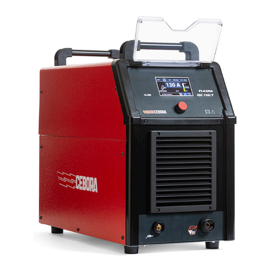
DESCRIZIONE GENERATORE Questo apparecchio è un generatore di corrente continua costante, progettato per il taglio di materiali elettroconduttori (metalli e leghe) mediante procedimento ad arco plasma. Insieme alla torcia costituisce un impianto per taglio plasma monogas (aria oppure azoto) completamente gestito da microprocessore, in grado di erogare una corrente max di 130 A. - Page 9 Fig. 1 Fig.4.1 Fig.4.1/a 3301329-IT...
-
Page 10: Spiegazione Dei Dati Tecnici Riportati Sulla Targa Della Macchina
Spiegazione dei dati tecnici riportati sulla targa della macchina Convertitore statico di frequenza trifase trasformatore-raddrizzatore. N°. Numero di matricola Caratteristica discendente Adatto per taglio al plasma P.A.C. Torch type Tipo di torcia che deve essere utilizzata con questo apparecchio per formare un sistema sicuro Tensione a vuoto secondaria (valore di picco) Fattore di servizio percentuale Esprime la percentuale di 10 minuti in cui l’apparecchio può... -
Page 11: Messa In Opera
MESSA IN OPERA Disimballo e sistemazione Utilizzare adeguati mezzi di sollevamento e spostamento. Il generatore, compreso della pedana di legno, ha un peso di circa 50 kg. Utilizzare adeguati mezzi di sollevamento e spostamento. Per rimuovere la pedana in legno facente parte dell'imballo: •... -
Page 12: Impiego
IMPIEGO All’accensione dell’apparecchio mediante l'interruttore B posto nel pannello posteriore del generatore, il display N visualizza: Fig. 6 ♦ nome della linea del generatore ♦ versione e data di rilascio del firmware del generatore Dopo qualche secondo, il display N visualizza la schermata principale in funzione della torcia riconosciuta: ♦... -
Page 13: Impostazioni (Settings)
6.1.1 Impostazioni (Settings) Fig. 6.1.1 Predisporre quindi: ♦ Selezione parametri (Parameter Selection) − Pannello (Panel): se si desidera gestire le impostazioni dal display del generatore tramite la manopola H − Modbus: se si desidera gestire le impostazioni del generatore tramite Modbus – RS485 (in tal caso occorre il kit art.502 e impostare Configurazione Modbus (Modbus Configuration) (RS485) = ON) ♦... -
Page 14: Taglio Su Grigliato (Modalità Di Lavoro "Fast Restart")
Nella Fig.6.1.2 viene indicato il set corretto di consumabili per la precedente impostazione. Premere il pulsante della torcia per accendere l’arco pilota. Se non si inizia il taglio, dopo 2 secondi l’arco pilota si spegne e quindi, per riaccenderlo, premere nuovamente il pulsante. Non tenere inutilmente acceso l’arco pilota in aria: in tal modo si aumenta il consumo dell’elettrodo, del diffusore e dell’ugello. -
Page 15: Marcatura Spot (Modalità Di Lavoro "Spot")
Alla fine del taglio, mantenendo premuto il pulsante, l'arco plasma rimane acceso passando in modalità arco pilota ed è quindi pronto per trasferire di nuovo senza nessun ritardo. Utilizzare questa funzione solo se necessario per evitare un' inutile usura dell'elettrodo e dell'ugello. 6.1.4 Marcatura spot (modalità... -
Page 16: Scriccatura (Modalità Di Lavoro "Gouge")
6.1.6 Scriccatura (modalità di lavoro ”GOUGE") Fig. 6.1.6 Fig. 6.1.6a Per eseguire operazioni di scriccatura, selezionare tale modalità. Questa operazione permette di togliere saldature difettose, dividere pezzi saldati, preparare lembi etc. Per questa operazione si deve usare l'ugello apposito (vedi Fig.6.1.6). Il valore di corrente da utilizzare varia da 60 A a 130 A in funzione dello spessore e della quantità... -
Page 17: Torcia Cp180C Dar
Fig. 6.1.6/b Torcia CP180C DAR Fig. 6.2 Ruotando la manopola H si selezionano le diverse voci, quali: Tipo di processo Tipo di materiale Gas di taglio Spessore del materiale Intervallo della corrente di lavoro Corrente di lavoro Pressione di lavoro Parametri del CNC Stato del generatore Impostazioni... -
Page 18: Impostazioni (Settings)
6.2.1 Impostazioni (Settings) Fig. 6.2.1 Predisporre quindi: ♦ Selezione parametri (Parameter Selection) − Pannello (Panel): se si desidera gestire le impostazioni dal display del generatore tramite la manopola H − Modbus: se si desidera gestire le impostazioni del generatore tramite Modbus – RS485 (in tal caso occorre il kit art.502 e impostare Configurazione Modbus (Modbus Configuration) (RS485) = ON) −... -
Page 19: Taglio (Modalità Di Lavoro "Cut")
6.2.2 Taglio (modalità di lavoro ”CUT”) Fig. 6.2.2 Scegliere, in sequenza: ♦ il tipo di materiale da tagliare (Acciaio Dolce - Mild Steel, Acciaio Inox - Stainless Steel o Alluminio - Aluminium) ♦ il gas di taglio (Aria - Air oppure Azoto N2) ♦... -
Page 20: Taglio Su Grigliato (Modalità Di Lavoro "Fast Restart")
6.2.3 Taglio su grigliato (modalità di lavoro ”FAST RESTART”) Fig. 6.2.3 Per tagliare lamiere forate o grigliati, selezionare tale modalità. Fare riferimento al paragrafo relativo alla modalità di lavoro CUT per: ♦ le impostazioni di materiale, gas e corrente di taglio; ♦... -
Page 21: Marcatura (Modalità Di Lavoro "Mark")
Gli intervalli di regolazione sono: ♦ corrente di marcatura spot = 10 - 39 A ♦ tempo di marcatura spot = 0.01 – 1.00 s 6.2.5 Marcatura (modalità di lavoro ”MARK") Fig. 6.2.5 La marcatura al plasma è un processo di incisione delle lamiere che permette di effettuare linee, disegni o caratteri alfanumerici. - Page 22 Fig. 6.3.1a Fig. 6.3.1b E’ possibile visualizzare tutti i parametri contenuti nelle tabelle di taglio relative alle impostazioni sopradescritte: ♦ Corrente Arco (Arc Current) ♦ Tensione Arco (Arc Voltage) ♦ Velocità di taglio - qualità (Cutting Speed - quality) ♦ Altezza Sfondamento (Pierce Height) ♦...
-
Page 23: Stato Macchina (Machine Status)
6.3.2 Stato macchina (Machine Status) Fig. 6.3.2 Fig. 6.3.2a E’ possibile visualizzare diversi parametri relativi all’utilizzo del generatore: ♦ Numero Accensioni (Power Up Counts): numero di accensioni del generatore ♦ Tempo di Accensione (Power Up Time): tempo totale di accensione del generatore ♦... -
Page 24: Informazioni (Information)
6.3.3 Informazioni (Information) Fig. 6.3.3 QR-code: rimanda alla pagina internet del generatore Nome e articolo del generatore Versione e data di rilascio del firmware del generatore 3301329-IT... -
Page 25: Sostituzione Dei Consumabili
SOSTITUZIONE DEI CONSUMABILI IMPORTANTE: spegnere il generatore prima di effettuare qualsiasi sostituzione di consumabili. In riferimento alla fig. 7 e 7/A, i particolari soggetti ad usura sono: l'elettrodo A, il diffusore B, l'ugello C e la protezione ugello E che devono essere sostituiti dopo aver svitato il portaugello D. Talvolta, per la torcia CP 180C, può rendersi necessario pulire la parte interna del diffusore B. -
Page 26: Qualita' Del Taglio
Nota: i dati presenti nelle tabelle di taglio sono ottenuti nei laboratori CEBORA S.p.A con consumabili nuovi. I punti seguenti possono aiutare l’utilizzatore ad apportare le variazioni necessarie all’ottenimento di un taglio di buona qualità. -
Page 27: Manutenzione E Riparazione
Pertanto, si consiglia di eseguire le operazioni elencate nella tabella seguente. Se, in seguito ad un controllo, si nota un componente eccessivamente usurato o un suo funzionamento non regolare, contattare il Servizio Assistenza CEBORA. PERIODO OPERAZIONI DI MANUTENZIONE Giornalmente •... -
Page 28: Codici Errore
♦ Sostituire sempre con materiale originale eventuali parti danneggiate della macchina o della torcia ♦ Utilizzare solo torce CEBORA tipo CP 180C Gli errori si dividono in due categorie: ♦ Errori hardware [E] non ripristinabili, a seguito dei quali è necessario riavviare il generatore. Vengono visualizzati su schermata con sfondo rosso. - Page 29 Errore nella lettura della tensione di collegato il generatore. Se il problema persiste, rete contattare il Servizio Assistenza CEBORA Verificare l’integrità dei fusibili del quadro elettrico Tensione di rete fuori specifica ove è collegato il generatore. Se il problema persiste,...
-
Page 30: Dati Tecnici
130 A - 132V 100% Tensione a vuoto (U0) 323 V 345 V 355 V 313 V 345 V Torcia Cebora CPXXX CP180C MAR - CP180C DAR Corrente di taglio (I2) 130 A Tensione di taglio (U2) 160 V Corrente primaria max (I1) - Page 31 EN INSTRUCTION MANUAL FOR PLASMA CUTTING Translation of the original instructions PLASMA iQC 130 T Art. 603 3301329-EN...
- Page 32 TABLE OF CONTENTS SYMBOLS ................................34 ............................... 34 arning label WARNINGS ................................ 35 ............................35 ifTing and TranSporT INSTALLATION ..............................35 ..............................35 ainS ConneCTion ........................36 nvironmenTal and STorage CondiTionS ............................... 36 aS CylinderS ............................. 36 eneral nformaTion POWER SOURCE DESCRIPTION ........................37 ..........................
- Page 33 PLASMA CUTTING INSTRUCTION MANUAL This manual is part of the overall documentation and is invalid unless it is used in conjunction with the following parts of the documentation that you can consult in the Support-Documentation section of the website welding.cebora.it: 3301151...
-
Page 34: Symbols
SYMBOLS The colour of the box indicates the category into which the operation falls: DANGER, WARNING, CAUTION, NOTICE or INSTRUCTION. DANGER Indicates a situation of imminent danger that could cause severe injury to people WARNING Indicates a situation of potential danger that could cause severe injury to people Indicates a situation of potential danger that could cause slight injury to people and CAUTION material damage to equipment if not respected... -
Page 35: Warnings
1.2 Cutting sparks can cause fires. Have a fire extinguisher nearby, and have a watchperson ready to use it. Do not cut on drums or any closed container. The plasma arc can cause injury and burns. Turn off power before disassembling torch. Do not grip material near cutting path. Wear complete body protection. Electric shock from torch or wiring can kill. Wear dry insulating gloves. -
Page 36: Environmental And Storage Conditions
DANGER ♦ Make sure that the mains voltage matches the voltage indicated on the specifications plate of the welding/ cutting power source. Connect a plug of adequate capacity for the current consumption I1 indicated on the data plate. Make sure that the yellow/green conductor of the power cable is connected to the plug’s earth contact. ♦ If mains power extensions are used, the cable supply cross-section must be appropriately sized. -
Page 37: Power Source Description
POWER SOURCE DESCRIPTION This equipment is a direct current continuous power source designed for plasma arc cutting of electro-conducting materials (metals and alloys). Along with the torch is a single-gas plasma cutting system (air or nitrogen), completely managed by a microprocessor , capable of delivering a maximum current of 130 A. All process parameters ( material, gas and current ) are selectable from the display and, according to their choice , the optimal flow of gas is automatically indicated. - Page 38 Fig. 1 Fig.4.1 Fig.4.1/a 3301329-EN...
-
Page 39: Explanation Of The Technical Specifications Listed On The Machine Plate
Explanation of the technical specifications listed on the machine plate Three-phase static transformer-rectifier frequency converter. N°. Serial number Drooping characteristic Suitable for plama cutting P.A.C. Torch type Welding torch type which has to be used with this equipment to correctly achieve a safe system Secondary open-circuit voltage (peak value) Duty cycle percentage. -
Page 40: Start Up
START UP Unpacking and placement Use appropriate lifting and handling measures. The power source, including its wooden pallet, weighs approximately 45 kg. Use appropriate lifting and handling measures. To remove the wooden pallet forming part of the packaging: ♦ Remove the fastening straps ♦... -
Page 41: Use
When the power source is turned on using switch B located on the rear panel of the power source, the display N shows: Fig. 6 ♦ name of the power source line ♦ power source firmware version and release date After a few seconds, the display N shows the main screen based on the recognized torch: ♦... -
Page 42: Impostazioni (Settings)
6.1.1 Impostazioni (Settings) Fig. 6.1.1 Then prepare ♦ Parameter Selection − Panel: If you want to manage the settings from the generator display using knob H − Modbus: if you want to manage the generator settings via Modbus – RS485 (in this case you need the kit art.502 and set Modbus Configuration (RS485) = ON) ♦... -
Page 43: Grid Cutting ("Fast Restart" Operating Mode)
Fig.6.1.2 shows the correct set of consumables for the previous setting. Press the torch trigger to light the pilot arc. If you do not start cutting, after 2 seconds the pilot arc will go out and then, to turn it back on, press the button again. Do not keep the pilot arc lit in the air unnecessarily: this will increase the consumption of the electrode, diffuser and nozzle. -
Page 44: Spot Marking ("Spot" Operating Mode)
At the end of the cut, by keeping the button pressed, the plasma arc remains lit, switching to pilot arc mode it is then ready to transfer again without any delay. Use this function only if necessary to avoid unnecessary wear of the electrode and nozzle. 6.1.4 Spot marking (”SPOT"... -
Page 45: Gouging ("Gouge" Operating Mode)
6.1.6 Gouging (”GOUGE" operating mode) Fig. 6.1.6 Fig. 6.1.6a To perform gouging operations, select this mode.. This operation allows you to remove faulty welds, divide welded pieces, prepare edges etc. For this operation you must use the appropriate nozzle (see Fig.6.1.6). The current value to be used varies from 60 A to 130 A depending on the thickness and quantity of material you want to remove. -
Page 46: Cp180C Dar Torch
Fig. 6.1.6/b CP180C DAR torch Fig. 6.2 Rotating knob H selects the different items, such as: Type of process Type of material Cutting gas Material thickness Working current range Working current Working pressure CNC parameters Generator status Settings Information Briefly press knob H on the selected item to enter edit mode (the background becomes white). Press again to return to selection mode. When the system is put into operation for the first time, some parameters must be set by accessing item (10) Settings 3301329-EN... -
Page 47: Settings
6.2.1 Settings Fig. 6.2.1 Then prepare: ♦ Parameter Selection − Panel: if you want to manage the settings from the generator display using knob H − Modbus: if you want to manage the generator settings via Modbus – RS485 (in this case you need the kit art.502 and set Modbus Configuration (RS485) = ON) − Connector: if you want to manage generator settings via CNC connector signals ♦... -
Page 48: Cutting ("Cut" Operating Mode)
6.2.2 Cutting (”CUT” operating mode) Fig. 6.2.2 Choose, in sequence: ♦ the type of material to be cut (Mild Steel, Stainless Steel or Aluminium) ♦ cutting gas (Air or Nitrogen N2) ♦ the thickness and the cutting current It is possible to adjust the cutting current within the selected range, following the instructions given in the cutting tables. -
Page 49: Grid Cutting ("Fast Restart" Operating Mode)
6.2.3 Grid cutting (”FAST RESTART” operating mode) Fig. 6.2.3 To cut perforated sheets or gratings, select this mode. Refer to the paragraph relating to the CUT operating mode for: ♦ material, gas and cutting current settings ♦ adjustment of the working pressure ♦... -
Page 50: Marking ("Mark"Operating Mode)
The adjustment ranges are: ♦ Spot marking current = 10 - 39 A ♦ Spot marking time = 0.01 – 1.00 s 6.2.5 Marking (”MARK"operating mode) Fig. 6.2.5 Plasma marking is a sheet metal engraving process that allows you to make lines, drawings or alphanumeric characters. Refer to the paragraph relating to the CUT working mode for: ♦... - Page 51 Fig. 6.3.1a Fig. 6.3.1b It is possible to view all the parameters contained in the cutting tables relating to the settings described above: ♦ Arc Current ♦ Arc Voltage ♦ Cutting Speed - quality ♦ Pierce Height ♦ Pierce Delay ♦ Cutting Height ♦...
-
Page 52: Machine Status
6.3.2 Machine Status Fig. 6.3.2 Fig. 6.3.2a It is possible to view various parameters relating to the use of the generator: ♦ Power Up Counts: number of generator starts ♦ Power Up Time: total time in which the generator remains on ♦... -
Page 53: Information
6.3.3 Information Fig. 6.3.3 QR-code: refers to the power source website Name and article of the power source Power sourcer firmware version and release date 3301329-EN... -
Page 54: Replacing Consumables
♦ Make sure that the new electrode and nozzle that are going to be assembled are perfectly clean and oil-free. ♦ To avoid welding torch damage always use Cebora original parts. 3301329-EN... -
Page 55: Cutting Quality
Note: data sheet listed in the cutting chart tables were obtained in CEBORA S.p.A laboratories testing with new consumables. -
Page 56: Repair And Maintenance
Therefore, we recommend to perform the operations listed in the table below. If, during an inspection, a highly worn component part is found or one that is not working properly, contact the CEBORA assistance service. PERIOD MAINTENANCE OPERATIONS Daily •... -
Page 57: Error Codes
To assure efficiency of these protective devices: ♦ Do not remove nor by-pass the protective devices. ♦ Replace them with original Cebora spare parts. ♦ Always replace any damaged parts of the machine or the welding torch with original parts. ♦ Use torches CEBORA Type CP 180C Errors are divided into two categories: ♦... - Page 58 Overtemperature on primary module temperature returns within the permitted limits. If the problem persists, contact the CEBORA Assistance Service Do not turn off the generator to maintain the fan in operation and thus have effective cooling. Normal...
-
Page 59: Technical Specifications
130 A - 132V 100% Tensione a vuoto (U0) 323 V 345 V 355 V 313 V 345 V Torcia Cebora CPXXX CP180C MAR - CP180C DAR Corrente di taglio (I2) 130 A Tensione di taglio (U2) 160 V Corrente primaria max (I1) - Page 60 CEBORA S.p.A - Via Andrea Costa, 24 - 40057 Cadriano di Granarolo - BOLOGNA - Italy Tel. +39.051.765.000 - Fax. +39.051.765.222 www.cebora.it - e-mail: cebora@cebora.it...
Need help?
Do you have a question about the PLASMA iQC 130 T and is the answer not in the manual?
Questions and answers