
Related Manuals for Cebora PLASMA PROF 123 ACC


Summary of Contents for Cebora PLASMA PROF 123 ACC
- Page 1 CEBORA S.p.A. PLASMA PROF 123 ACC POWER SOURCE art. 956 SERVICE MANUAL 3.302.269 12/04/2012...
-
Page 2: Table Of Contents
3.3 - Troubleshooting..........10 4 - COMPONENTS LIST......... 33 3.3.1 - The Power Source does not start, operator 4.1 - Plasma PROF 123 ACC : see file ESP956.pdf panel off..........10 enclosed at the end of the manual....33 3.3.2 - Power Source powered, operator panel on,... -
Page 3: General Information
It is forbidden to attempt to repair damaged electronic boards or modules; replace them with original Cebora spare parts. 1.3 - Safety information. The safety notes provided in this Manual are an integral part of those given in the Instruction Manual. -
Page 4: System Description
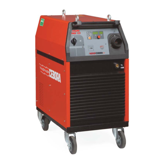
2 - SYSTEM DESCRIPTION. 2.1 - Introduction. The PLASMA PROF 123 ACC is a cutting system, designed for plasma arc cutting of electro- conducting materials. It consists of an electronic Power Source art. 956 and a set of torches and accessories, to be used in manual applications (see list in the Sales Catalogue). - Page 5 CEBORA S.p.A. The J1 terminal of the power board (56) corresponds to the positive output (3) of the igbt module as well and represents the nozzle potential output. The nozzle resistor (33) which facilitates the operation with the pilot arc is connected to it. On this connection as well, inside the power board (56), the Hall effect current transducer is connected which sends to the control board (47) the pilot arc current signal.
- Page 6 CEBORA S.p.A. The control board (47) receives the temperature signals originating from the thermostats placed on the transformer (37) and on the igbt module dissipater on the power board (56). According to these over-temperature signals, the Power Source is stopped and the corresponding error code is displayed on the operator panel.
-
Page 7: Maintenance
CEBORA S.p.A. 3 - MAINTENANCE. WARNINGS ANY INTERNAL INSPECTIONS OR REPAIRS MUST BE CARRIED OUT BY QUALIFIED PERSONNEL. BEFORE BEGINNING MAINTENANCE OPERATIONS, UNPLUG THE MACHINE FROM THE MAINS AND WAIT FOR THE INTERNAL CAPACITORS TO DISCHARGE (1 MINUTE). 3.1 - Periodic inspection, cleaning. -
Page 8: Power Source Operation
CEBORA S.p.A. 3.2.2 - Power Source operation. WARNING! DURING THE FOLLOWING TESTS DO NOT AIM THE TORCH AT PEOPLE OR PARTS OF THE BODY, BUT ONLY TOWARDS AN OPEN SPACE OR THE WORKPIECE. NOTES Operations preceded by this symbol refer to operator actions. - Page 9 CEBORA S.p.A. Correct? NO (see 3.3.3). Hold down the torch start button for a very short time. ♦ Gas flows from the torch for 40 seconds. The pressure reading on the pressure gauge (I) remains constant. Correct? NO (see 3.3.4, 3.3.5).
-
Page 10: Troubleshooting
CEBORA S.p.A. 3.3 - Troubleshooting. WARNINGS ANY INTERNAL INSPECTIONS OR REPAIRS MUST BE CARRIED OUT BY QUALIFIED PERSONNEL. SWITCH (A) IS A FUNCTION SWITCH NOT A GENERAL SWITCH. FOR THIS REASON INSIDE THE POWER SOURCE A VOLTAGE IS PRESENT WHICH IS DANGEROUS EVEN WHEN THE SWITCH IS SET TO “0”. - Page 11 CEBORA S.p.A. MAINS CONNECTION TEST. Mains terminal board (5), terminals U1, V1, W1 = 3 x 230/400/440 Vac according to mains voltage. Correct? ♦ Check power cable and plug and replace if necessary. ♦ Check the mains voltage conditions. SERVICE TRANSFORMER (53) POWER SUPPLY TEST.
- Page 12 CEBORA S.p.A. CONTROL BOARD (47) POWER SUPPLY TEST. Control board (47), connector J1, terminals 1 - 2 = 24 Vac (start button, torch recognition, central adapter protection circuits power supply). Control board (47), connector J10, terminals 7 - 14 = 27 Vac (solenoid valves, contactors, pre-charge relay on pre-charge board (3) power supply).
-
Page 13: Power Source Powered, Operator Panel On, Fan (23) Stopped
CEBORA S.p.A. 3.3.2 - Power Source powered, operator panel on, fan (23) stopped. WARNING SOME PRE-CHARGE BOARD (3) CIRCUITS ARE LIVE EVEN WITH SWITCH (49) OPEN. UNPLUG THE POWER SOURCE FROM THE MAINS SOCKET IN ORDER TO WORK WITHOUT ANY DANGEROUS VOLTAGE. -
Page 14: Power Source Powered, Display And
POWER SUPPLY TEST, of par. 3.3.1. ♦ Make sure that the correct program is loaded in control board (47), performing the programming procedure “Firmware updating” available on the Cebora Web site, if necessary (on art. 956 Power Source, the Firmware update is possible by connecting a Personal Computer directly to the BD1 connector on control board (47)). -
Page 15: The Start Command Produces No Effect
CEBORA S.p.A. 3.3.4 - The start command produces no effect. START COMMAND TEST. Control board (47), terminals J6-A(+) and J6-B(-) = 0 Vdc, with start button pressed; +33 Vdc with start button released. Correct? ♦ Replace control board (47). ♦ Check the wiring between terminals J6-A and J6-B of control board (47), central adapter (41), torch button and contact of the nozzle guard on the torch. -
Page 16: No Gas Flows From The Torch
Correct? ♦ Check for presence of gas at the intake fitting (I) and make sure the pressure and flow rate in the supply line meet specifications values of Plasma PROF 123 ACC (see Instruction Manual and Sales Catalogue). ♦ Make sure there are no occlusions in the gas hoses of the Power Source or in the flow reducer inserted on the solenoid valve V01 (14) body. -
Page 17: Gas Flows From The Torch, Pilot Arc Does Not Start (No Nozzle Voltage)
CEBORA S.p.A. 3.3.6 - Gas flows from the torch, pilot arc does not start (no nozzle voltage). POWER SOURCE OUTPUT VOLTAGE TEST. Power board (56), terminals TP1(+) – TP6(or terminal 1 of igbt module)(gnd) = fig. 5.2.1a (+280 Vdc approximately) Power Source output voltage with pilot arc off, for 2.5 seconds (pilot arc maximum time), with start button pressed. -
Page 18: Gas Flows From The Torch, Pilot Arc Does Not Start (No High Frequency)
CEBORA S.p.A. 3.3.7 - Gas flows from the torch, pilot arc does not start (no high frequency). NOZZLE VOLTAGE TEST. Power board (56), terminal TP6(or terminal 1 of igbt module)(gnd) and terminal J4(+) on sensor board (52) = fig. 5.2.2a (+280 Vdc approximately, contactor (55) closed) nozzle voltage with pilot arc off, for 2.5 seconds (pilot arc maximum time), with start button pressed. - Page 19 CEBORA S.p.A. ♦ Check the wiring between HF transformer (50) and electrode terminal on central adapter (41). If you find loose connections, tighten and replace any damaged components. ♦ Check the wiring between J2 on sensor board (52) and nozzle terminal on central adapter (41).
-
Page 20: In Open Circuit Operation, The Output Voltage Is Not Regular
CEBORA S.p.A. 3.3.8 - In open circuit operation, the output voltage is not regular. POWER SOURCE OUTPUT VOLTAGE TEST. Power board (56), terminals TP1(+) – TP6(or terminal 1 of igbt module)(gnd) = fig. 5.2.1b (+160 Vdc approximately) Power Source output voltage with pilot arc on, for 2.5 seconds (pilot arc maximum time), with start button pressed. - Page 21 CEBORA S.p.A. POWER SOURCE OUTPUT CURRENT TRANSDUCER POWER SUPPLY TEST. Power board (56), connector J3, terminals 2(+) - 3(-) = +15 Vdc; terminals 4(+) - 3(-) = -15 Vdc. Correct? ♦ Check the wiring between J3 power board (56) and J3 control board (47).
-
Page 22: Irregular Pilot Arc Striking, Unstable Pilot Arc
♦ Make sure that the pressure regulator (L) is working properly; replace it if defective. ♦ Make sure that gas pressure and flow rate in the supply line meet specifications of Plasma PROF 123 ACC (see Instruction Manual). ♦ Check the following conditions of solenoid valves (13) and (14), during pilot arc phases: - V01 (pilot arc solenoid valve (14)) = opened = 27 Vac on coil terminals. - Page 23 CEBORA S.p.A. ♦ Check the wiring between terminals TP6 of power board (56), choke (35), HF transformer (50) and electrode terminal on central adapter (41). If you find loose connections, tighten and replace any damaged components. ♦ Check the wiring between J1 power board (56), nozzle resistor (33), contactor (55), terminal J4 on sensor board (52) and between terminal J2 sensor board (52) and nozzle terminal on central adapter (41).
-
Page 24: There Is No Transfer Arc Or It Is Too Weak To Perform Cutting
CEBORA S.p.A. 3.3.10 - There is no transfer arc or it is too weak to perform cutting. NOZZLE CURRENT TRANSDUCER POWER SUPPLY TEST. Power board (56), connector J2, terminals 2(+) - 3(-) = +15 Vdc; terminals 4(+) - 3(-) = -15 Vdc. - Page 25 CEBORA S.p.A. Correct? ♦ Replace the control (47) and/or power board (56). ♦ Make sure that the gas lines of Power Source are not clogged and, if necessary, perform the PLASMA GAS PRESSURE TEST of par. 3.3.9.. ♦ Check for the correct opening of solenoid valve V03 (13)(27 Vac on coil terminals) in cutting operation.
-
Page 26: Error Codes And Alarm Signals
CEBORA S.p.A. 3.4 - Error codes and alarm signals. 3.4.1 - 02 - Hardware lockup. Block due to user data memory writing error. Replace control board (47). 3.4.2 - 30 - Minimum current signal error from power board (56) (current transducer offset). -
Page 27: 40 - Dangerous Voltage
CEBORA S.p.A. ♦ With Power Source off, temporarily disconnect J4 from control board (47) and check resistance between terminals 1 and 3 of J4 on control board (47). Correct value = approximately 21 Kohm. If incorrect, replace control board (47). -
Page 28: 49 - Nozzle Current During Cutting
3.4.8 - 51 - Torch recognition failed. This alarm signals that the inserted torch is not suitable for the Power Source. On Plasma PROF 123 ACC actually is possible to install cutting torch CP161 (artt. 1230 or 1231), which is provided with an automatic recognition system. -
Page 29: 53 - "Trg" On Displays (U). Start Button Pressed At Start-Up Or During Operating Mode Reset
CEBORA S.p.A. CP161 TORCH RECOGNITION TEST Control board (47), connector J9 = signals according to following table with torch CP161 inserted in the central adapter (41). Torch type Voltage on J9 terminals on control board (47) 2 - 3 2 - 4... -
Page 30: 67 - Mains Voltage Does Not Meet Specifications
CEBORA S.p.A. ♦ Check delivery of output voltage, performing, if necessary, the tests in par. 3.3.6., taking special care the NOZZLE VOLTAGE TEST of par. 3.3.6. ♦ Replace sensor board (52) and/or control board (47). ♦ With Power Source off, temporarily disconnect J5 from sensor board (52) and check the resistance between terminals J4 and 1 of J5 on sensor board (52). -
Page 31: 73 - "Th""0" On Displays (U) (V). Transformer (37) High Temperature
CEBORA S.p.A. ♦ With Power Source off, temporarily disconnect J19 from control board (47) and check the resistance between terminals 1 and 2 of J19 on control board (47). Correct value = junction of two diodes in both measure directions. If incorrect, replace control board (47). -
Page 32: 78 - "Gas""Lo" On Displays (U) (V). Gas Low Pressure
CEBORA S.p.A. 3.4.14 - 78 - “GAS”“LO” on displays (U) (V). Gas low pressure. This alarm signals that plasma gas pressure is below the minimum value allowed for a correct operation. The pressure signal is supplied by the pressure switch (15). -
Page 33: Components List
CEBORA S.p.A. 4 - COMPONENTS LIST. 4.1 - Plasma PROF 123 ACC : see file ESP956.pdf enclosed at the end of the manual. 4.2 - Components table: see file ESP956.pdf enclosed at the end of the manual. 5 - ELECTRICAL DIAGRAMS. -
Page 34: Hf Board (27) Input Voltage = Pilot Arc Voltage (Par. 3.3.7, 3.4.10)
CEBORA S.p.A. a) with pilot arc off b) with pilot arc on 5.2.3 - HF board (27) input voltage = pilot arc voltage (par. 3.3.7, 3.4.10). 5.2.4 - Pilot arc current reference signal (par. 3.3.8). 5.2.5 - Power Source output current 5.2.6 - Nozzle current feedback signal... -
Page 35: Fuse Board (53), Code 5.602.403
CEBORA S.p.A. 5.3 - Fuse board (53), code 5.602.403. 5.3.1 - Topographical drawing. 5.3.2 - Connector and fuse table. Conn. Terminals Fuse Value Function 1 - 2 1.25 A 20 Vac output, driver board (56) power supply. 4 - 5 1.25 A... -
Page 36: Pre-Charge Board (3), Code 5.602.415
CEBORA S.p.A. 5.4 - Pre-charge board (3), code 5.602.415. 5.4.1 - Topographical drawing. 5.4.2 - Connector and fuse table. Conn. Terminals Function 1 - 2 3 - 4 transformer (37) pre-magnetization relay command input. 5 - 6 B(+) - A(-) +280 Vdc input from DC-capacitor (20), for load resistors on pre-charge board (3). -
Page 37: Measure Board (57), Code 5.602.388
CEBORA S.p.A. 5.5 - Measure board (57), code 5.602.388. 5.5.1 - Topographical drawing. 5.5.2 - Connector table. Conn. Terminals Function 1-3-5 rectifier bridge (34) three phase voltage supply input. 1(+) - 2(-) “suitable mains voltage” signal output. 3-4-5 Gnd. 3.302.269... -
Page 38: Supply Board (51), Code 5.602.299/D
CEBORA S.p.A. 5.6 - Supply board (51), code 5.602.299/D. 5.6.1 - Topographical drawing. 5.6.2 - Connector table. Conn. Terminals Function 1(+) - 2(-) + 15 Vdc output for control board (47) power supply. 3(+) - 2(-) -15 Vdc-1 output for control board (47) power supply. -
Page 39: Control Board (47), Code 5.602.398/A
CEBORA S.p.A. 5.7 - Control board (47), code 5.602.398/A. 5.7.1 - Topographical drawing. 3.302.269 12/04/2012... - Page 40 CEBORA S.p.A. 5.7.2 - Connector table. Conn. Terminals Function 1 - 2 24 Vac input for services power supply (start button, torch recognition, central adapter (41) protection circuits). 1(+) - 2(-) “UV” signal input (control board (47) power supply incorrect voltage).
-
Page 41: Power Board (56), Code 5.602.401
CEBORA S.p.A. 5.8 - Power board (56), code 5.602.401. 5.8.1 - Topographical drawing. 5.8.2 - Connector table. Conn. Terminals Function output voltage output, nozzle potential (+). “nozzle current” signal output. 2(+) - 3(-) +15Vdc input for nozzle current transducer power supply. -
Page 42: Driver Board (56), Code 5.602.396
CEBORA S.p.A. 5.9 - Driver board (56), code 5.602.396. 5.9.1 - Topographical drawing. 5.9.2 - Connector table. Conn. Terminals Function 1 - 2 20 Vac input for driver board (56) power supply. 5(+) - 4(-) power board (56) igbt command input. -
Page 43: Hf Board (27), Code 5.602.034/B
CEBORA S.p.A. 5.11 - HF board (27), code 5.602.034/B. 5.11.1 - Topographical drawing. 5.11.2 - Connector table. Conn. Terminals Function CN1 - CN4 output for HF transformer (50) primary circuit. Power Source output voltage input (nozzle potential). Power Source output voltage input (electrode potential). - Page 44 ESP956.pdf...
- Page 45 ESP956.pdf DESCRIZIONE DESCRIPTION DESCRIZIONE DESCRIPTION 38 PANNELLO ANTERIORE FRONT PANEL 01 LATERALE SINISTRO LEFT SIDE PANEL 39 PRESA GIFAS GIFAS SOCKET 02 TELERUTTORE CONTACTOR 40 CORNICE FRAME 03 CIRCUITO DI PRECARICA PRECHARGE CIRCUIT 41 ADATTATORE FISSO FIXED ADAPTOR 04 CONNESSIONE CONNECTION 42 PROTEZIONE TORCIA TORCHE PROTECTION...
- Page 46 SCHE956.pdf...
- Page 47 CEBORA S.p.A. ® CEBORA S.p.A. Via Andrea Costa n° 24 – 40057 Cadriano di Granarolo – Bologna – Italy Tel. +39 051765000 – Telefax: +39 051765222 http://www.cebora.it – E-Mail: cebora@cebora.it 3.302.269 12/04/2012...
- Page 48 CEBORA S.p.A. ® CEBORA S.p.A. Via Andrea Costa n° 24 – 40057 Cadriano di Granarolo – Bologna – Italy Tel. +39 051765000 – Telefax: +39 051765222 http://www.cebora.it – E-Mail: cebora@cebora.it 3.302.269 12/04/2012...
Need help?
Do you have a question about the PLASMA PROF 123 ACC and is the answer not in the manual?
Questions and answers