
Related Manuals for Cebora PLASMA PROF 162


Summary of Contents for Cebora PLASMA PROF 162
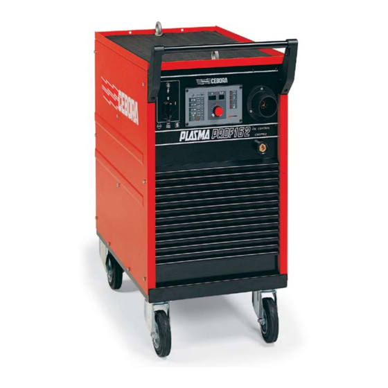
- Page 1 CEBORA S.p.A. PLASMA PROF 162 POWER SOURCE art. 952 SERVICE MANUAL 3.302.002 03/08/00...
-
Page 2: Table Of Contents
CEBORA S.p.A. CONTENTS - GENERAL INFORMATION............................4 - Introduction................................4 - General service policy............................4 - Safety information..............................4 - Electromagnetic compatibility..........................4 - SYSTEM DESCRIPTION............................5 - Introduction................................5 - Technical specifications............................5 - Description of power source art. 952.......................5 - MAINTENANCE.................................8 - Periodic inspection, cleaning..........................8 - Operating sequence............................8 3.2.1... - Page 3 CEBORA S.p.A. - ELECTRICAL DIAGRAMS...........................26 - Power source art. 952 : see file SCHE952.pdf enclosed at the end of the manual........26 - Waveforms.................................26 5.2.1 - Pilot arc current set-point (par.3.3.6 – 3.3.8)....................26 5.2.2 - Pilot arc current feed-back (par. 3.3.8)......................26 5.2.3...
-
Page 4: General Information
It is forbidden to attempt to repair damaged electronic boards or modules; replace them with original Cebora spare parts. 1.3 - Safety information. The safety notes provided in this manual are an integral part of those given in the Instruction Manual. -
Page 5: System Description
2 - SYSTEM DESCRIPTION 2.1 - Introduction. The PLASMA PROF 162 is a plasma arc system for cutting electrically conductive materials, which includes the electronic power source art. 952, and a set of torches and accessories, for use in both manual applications and automated systems (see list in Sales Catalogue). - Page 6 CEBORA S.p.A. The fixed fitting of the torch (50) is a multiple connector with a built-in power start for the torch electrode, two contacts for the torch gas nozzle, two contacts for the start button, four contacts to recognize the type of torch, and a pneumatic actuator for the plasma gas. The torch is connected to this fitting;...
- Page 7 CEBORA S.p.A. The torch board (68) acts as an input interface and condition for those signals especially affected by disturbances, as they come from critical areas of the system. These signals include: − Start from torch button; − Start from rear connector for remote control art. 197;...
-
Page 8: Maintenance
CEBORA S.p.A. 3 - MAINTENANCE WARNINGS ANY INTERNAL INSPECTIONS OR REPAIRS MUST BE CARRIED OUT BY QUALIFIED PERSONNEL. BEFORE BEGINNING MAINTENANCE OPERATIONS, UNPLUG THE MACHINE FROM THE MAINS AND WAIT FOR THE INTERNAL CAPACITORS TO DISCHARGE (2 MINUTES) 3.1 - Periodic inspection, cleaning. - Page 9 CEBORA S.p.A. Turn the gas setting knob (H) to a pressure, as read on the pressure gauge (G), suited to the type of torch being used (see table (S) on operator panel). Turn the knob (Z) to a cutting current suited to the thickness of the workpiece (see Instruction Manual).
-
Page 10: Power Source Commands And Signals
CEBORA S.p.A. 3.2.1 - Power source commands and signals. 3.3 - Troubleshooting. WARNINGS ANY INTERNAL INSPECTIONS OR REPAIRS MUST BE CARRIED OUT BY QUALIFIED PERSONNEL. THE SWITCH (A) IS A FUNCTION SWITCH, NOT A MAIN POWER SWITCH. THIS IS WHY THERE IS HAZARDOUS VOLTAGE PRESENT INSIDE THE POWER SOURCE EVEN WHEN THE SWITCH IS SET TO “0”. - Page 11 CEBORA S.p.A. ♦ Correctly position the voltage changes. ♦ Remove any short-circuits on the transformer connections (79). ♦ Make sure that the bridge (78) is not short-circuited. ♦ Make sure that the remote switch (5) does not have stuck contacts, or that it is not ordered to close before the capacitor (40) has been fully pre-charged and the transformer (79) fully pre-magnetized.
-
Page 12: Power Source Powered, Operator Panel (64) On, Fan (77) Stopped
CEBORA S.p.A. 3.3.2 - Power source powered, operator panel (64) on, fan (77) stopped. CAPACITOR PRE-CHARGING (40) AND TRANSFORMER PRE-MAGNETIZATION (79) TEST. Capacitor (40), terminals + and – = > 200 VDC, and remote switch (5) closed, after closing the switch (60). -
Page 13: Power Source Powered, Display And Signals Doe Not Indicate The Correct Values
CEBORA S.p.A. 3.3.3 - Power source powered, display and signals doe not indicate the correct values. LAMP-TEST AND SELF-TEST. The lamp-test (all operator panel signals lit) and self-test functions (display (X) indicates the software version installed) take place during the first two seconds after the machine is switched on. - Page 14 CEBORA S.p.A. COOLING UNIT TEST (only with CP200 torch). Control board (62), connector J5, terminals 2 – 4 = 0 VDC (unit activated); Control board (62), connector J5, terminals 3 – 4 = 0 VDC (pressure OK). Correct? ♦ See Cooling Unit Service Manual art. 1339.
-
Page 15: No Gas Flows From The Torch
CEBORA S.p.A. 3.3.5 - No gas flows from the torch. PILOT ARC SOLENOID VALVE TEST. Solenoid valve terminals (29), EL1 (terminals 7 – 8 of J12 control board (62), or EL2 (terminals 5 - 6 of J12 control board (62) = 27 VAC for two minutes (post-gas), with torch button pressed. -
Page 16: Gas Flows From The Torch, Pilot Arc Does Not Light (Igbt Output Voltage Missing)
CEBORA S.p.A. 3.3.6 - Gas flows from the torch, pilot arc does not light (IGBT output voltage missing). VOLTAGE TEST AT IGBT OUTPUT. Terminals 1 – 3 of IGBT (72) = 260 VDC with rated mains voltage, after pressing start button and for a duration of 2 seconds (maximum pilot arc time). -
Page 17: Gas Flows From The Torch, The Pilot Arc Does Not Light (High Frequency Missing)
CEBORA S.p.A. 3.3.7 - Gas flows from the torch, the pilot arc does not light (high frequency missing). NOTE The following tests may be checked only in the two seconds after pressing the torch start button (maximum pilot arc time). -
Page 18: Irregular Pilot Arc Starts, Unstable Pilot Arc
CEBORA S.p.A. TORCH BOARD INPUT VOLTAGE TEST. Torch board (68), connector J5 terminals AB and connector J7 terminal 1= > 200 VDC. Correct? ♦ Check the wiring between connectors J6 on board (68) and J7 on board (15). ♦ Replace board (68). - Page 19 CEBORA S.p.A. VOLTAGE TEST AT IGBT INPUT. Terminals 2 - 3 of IGBT (72) = 260 VDC, with rated mains voltage, stable even with pilot arc lit (- 10% max.). Correct? ♦ Check 3 x 180 VAC, with rated mains voltage, on input terminals of rectifier bridge (78);...
-
Page 20: Transfer Arc Does Not Take Place, Pilot Arc Remains And Cutting Is Impossible
CEBORA S.p.A. 3.3.9 - Transfer arc does not take place, pilot arc remains and cutting is impossible. REED TEST. Board (62), connector J8, terminals 1 – 2 = 0 VDC (reed contact closed) with pilot arc lit and torch next to workpiece. -
Page 21: Weak Transfer Arc That Shuts Off As Soon As Cutting Begins
CEBORA S.p.A. 3.3.10 - Weak transfer arc that shuts off as soon as cutting begins. NOZZLE REMOTE SWITCH OPENING TEST. Resistor terminals (74) = 0 VDC, with transfer arc (> 25 VDC with pilot arc). Correct? ♦ Check voltage on the remote switch coil (18): if 0 VAC replace remote switch (18);... -
Page 22: Error Messages
CEBORA S.p.A. 3.4 - Error messages. E1 - Hardware lockup. E2 - Hardware lockup. Power source lockup due to software error. Replace control board (62). E12 - Transfer reed closed during start-up. REED TEST. Power source powered, board (62), connector J8, terminals 1 – 2 = 35 VDC. -
Page 23: E51 - Torch Not Recognized
CEBORA S.p.A. E51 - Torch not recognized. TORCH RECOGNITION TEST. Control board (62), connector J3, terminals 1, 2, 3 – 4 = 1.2 VDC according to table below. Type of torch Voltage on terminals of J3 board (62) Jumpers (T) on torch adapter 1 –... -
Page 24: E54 - Short-Circuit Between Electrode And Nozzle
CEBORA S.p.A. To reset this situation, shut off the power source, remove the start command and restart the power source. E54 - Short-circuit between electrode and nozzle. E55 - Electrode finished. NOTE These functions are controlled only during cutting (transfer arc). -
Page 25: Components List
CEBORA S.p.A. 4 - COMPONENTS LIST 4.1 - Power source art. 952 : see file ESP952.pdf enclosed at the end of the manual. 4.2 - Components table: see file ESP952.pdf enclosed at the end of the manual. 4.3 - Spare parts list. -
Page 26: Electrical Diagrams
CEBORA S.p.A. 5 - ELECTRICAL DIAGRAMS 5.1 - Power source art. 952 : see file SCHE952.pdf enclosed at the end of the manual. 5.2 - Waveforms. 5.2.1 - Pilot arc current set-point (par.3.3.6 – 3.3.8). 5.2.2 - Pilot arc current feed-back (par. 3.3.8). -
Page 27: Fuse Board (8) Code 5.602.025
CEBORA S.p.A. 5.3 - Fuse board (8) code 5.602.025. 5.3.1 - Topographical drawing. 5.3.2 - Connector and fuse table. Connector Terminals Fuse Value Function A – B 1,25 A 180 VAC capacitor pre-charge output (40). 1 – 2 18 VAC driver board power supply output (9). -
Page 28: Pre-Charge Board (7) Code 5.602.026/A
CEBORA S.p.A. 5.4 - Pre-charge board (7) code 5.602.026/A. 5.4.1 - Topographical drawing. 5.4.2 - Connector and fuse table. Connector Terminals Function 1 – 4 180 VAC capacitor pre-charge input (40). 1 – 2 “capacitor pre-charge (40) complete” signal output. -
Page 29: Control Board (62) Code 5.602.027/A
CEBORA S.p.A. 5.5 - Control board (62) code 5.602.027/A. 5.5.1 - Topographical drawing. 5.5.2 - Connector table. Conn. Terminals Function 1 – 4 “transfer arc” output. 3 – 4 current digital reference input. 1 – 2 current set-point PWM output. -
Page 30: Driver Board (9) Code 5.602.023/A
CEBORA S.p.A. 5.6 - Driver board (9) code 5.602.023/A. 5.6.1 - Topographical drawing. 5.6.2 - Connector table. Connector Terminals Function 1 – 2 18 VAC driver board power supply input (9). 5 – 6 20 VAC IGBT driver power supply input. -
Page 31: Hf Board (15) Code 5.602.024
CEBORA S.p.A. 5.7 - HF Board (15) code 5.602.024. 5.7.1 - Topographical drawing. 5.7.2 - Connector table. Connector Terminals Function 1 – 2 "hazardous voltage" output. 5 – 6 PWM “electrode finished” output. 1 – 2 HF board power supply input (15). -
Page 32: Torch Board (68) Code 5.602.022/A
CEBORA S.p.A. 5.8 - Torch board (68) code 5.602.022/A 5.8.1 - Topographical drawing. 5.8.2 - Connector table. Connector Terminals Function 2-3-4-5 torch recognition input. A - B start input from torch button. A – B torch board power supply input (68). -
Page 33: Operator Panel Board (64) Code 5.602.028
CEBORA S.p.A. 5.9 - Operator panel board (64) code 5.602.028. 5.9.1 - Topographical drawing. 5.9.2 - Connector table. Connector Terminals Function 1 - 34 inputs/outputs from control board (62). 3.302.002 03/08/00... -
Page 34: Upgrades
CEBORA S.p.A. 6 - UPGRADES 6.1 - Power source art. 952 with enhanced pilot arc lighting. 6.1.1 - Description of upgrade. Valid for machines with serial N° A67063 and later. The purpose of this upgrade is a variation to improve pilot arc lighting. - Page 36 DESCRIZIONE DESCRIPTION DESCRIZIONE DESCRIPTION 41 SUPPORTO SUPPORT COPERCHIO COVER 42 SUPPORTO SUPPORT GOLFARA EYEBOLT 43 IMPEDENZA CHOKE COPERTURA GOMMA RUBBER MAT 44 RUOTA FISSA FIXED WHEEL FERRITE FERRITE 45 RINFORZO REINFORCEMENT TELERUTTORE CONTACTOR 46 FONDO BOTTOM LATERALE SINISTRO LEFT SIDE PANEL 47 RUOTA WHEEL CIRCUITO DI PRECARICA...
- Page 38 CODIFICA COLORI WIRING DIAGRAM FARBENCODIERUNG CODIFICACION CABLAGGIO ELETTRICO COLOUR CODE ELEKTRISCHE COLORES CABLAJE SCHALTPLAN ELECTRICO NERO BLACK SCHWARZ NEGRO ROSSO ROJO GRIGIO GREY GRAU GRIS BIANCO WHITE WEISS BLANCO VERDE GREEN GRÜN VERDE VIOLA PURPLE VIOLETT VIOLA GIALLO YELLOW GELB AMARILLO BLUE BLAU...
Need help?
Do you have a question about the PLASMA PROF 162 and is the answer not in the manual?
Questions and answers