
Related Manuals for Cebora PLASMA PROF 80


Summary of Contents for Cebora PLASMA PROF 80
- Page 1 CEBORA S.p.A. PLASMA PROF 80 POWER SOURCE art. 947 SERVICE MANUAL 3.302.167 25/06/04...
-
Page 2: Table Of Contents
CEBORA S.p.A. CONTENTS - GENERAL INFORMATION......................3 - Introduction............................3 - General service policy........................3 - Safety information..........................3 - Electromagnetic compatibility.......................3 - SYSTEM DESCRIPTION........................4 - Introduction............................4 - Technical specifications.........................4 - Description of power source art. 947.....................4 - MAINTENANCE ..........................6 - Periodic inspection, cleaning. -
Page 3: General Information
It is forbidden to attempt to repair damaged electronic boards or modules; replace them with original Cebora spare parts. 1.3 - Safety information. The safety notes provided in this manual are an integral part of those given in the Instruction Manual. -
Page 4: System Description
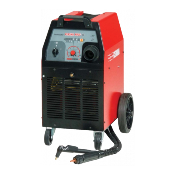
2 - SYSTEM DESCRIPTION 2.1 - Introduction. The PLASMA PROF 80 is a system for cutting electrically conductive materials, using a plasma arc process. It is made up of an electronic power source (art. 947), and a set of accessories for use in both manual applications and automated systems (see list in Sales Catalogue). - Page 5 CEBORA S.p.A. checking the signals originating from the pressure switch (35), thermostat in the transformer (50) and reed sensor (14) on the protection of the central adapter (12). The pressure switch (35) inserted on the plasma gas line stops the power source and lights the led (L) when the pressure falls below the minimum permitted value.
-
Page 6: Maintenance
CEBORA S.p.A. 3 - MAINTENANCE WARNINGS ANY INTERNAL INSPECTIONS OR REPAIRS MUST BE CARRIED OUT BY QUALIFIED PERSONNEL. DISCONNECT THE POWER SOURCE FROM THE MAINS BEFORE PERFORMING MAINTENANCE. 3.1 - Periodic inspection, cleaning. Periodically remove dirt and dust from the internal parts of the power source, using a jet of low-pressure dry compressed air or a brush. -
Page 7: Power Source Operation
CEBORA S.p.A. 3.2.2 - Power source operation. System shut off and unplugged from the mains. Connect the gas intake to the fitting (B) on the rear panel. Turn the gas setting knob (E) to a pressure, as read on the pressure gauge (F), suited to the type of torch being used (see Instruction Manual). -
Page 8: Troubleshooting
CEBORA S.p.A. 3.3 - Troubleshooting. WARNINGS ANY INTERNAL INSPECTIONS OR REPAIRS MUST BE CARRIED OUT BY QUALIFIED PERSONNEL. BEFORE REMOVING THE PROTECTIVE GUARDS AND ACCESSING INTERNAL PARTS, DISCONNECT THE POWER SOURCE FROM THE MAINS. NOTE Items in boldface describe problems that may occur on the machine (symptoms). - Page 9 CEBORA S.p.A. SERVICES POWER SUPPLY TEST. Fuse board (18): terminals J4 = approx. 230 Vac; terminals J5 = approx. 230 Vac; connector J1, terminals 1 and 2 = approx. 24 Vac; connector J2, terminals 1 and 2 = approx. 27 Vac;...
-
Page 10: Power Source Powered, Led (V) Lit, Fan (45) Stopped
CEBORA S.p.A. 3.3.2 - Power source powered, led (V) lit, fan (45) stopped. FAN (45) TEST. Fuse board (18), connector J5, terminals A and B = approximately 230 Vac, with switch (8) closed, both with mains at 230 and at 400 Vac. -
Page 11: No Gas Flows From The Torch
CEBORA S.p.A. 3.3.4 - No gas flows from the torch. PILOT ARC SOLENOID VALVE EL1 (37) TEST. Solenoid valve EL1 (37) terminals = approximately 26 Vac, with torch button pressed. The solenoid valve opening time also depends on the post-gas time. - Page 12 CEBORA S.p.A. source powered. If incorrect, carry out the MAINS CONNECTION TEST in par. 3.3.1. If correct make sure fuse F1 on the power board (20) is intact, and replace the power board (20) if necessary. ♦ Replace the power board (20).
-
Page 13: Gas Flows From The Torch, The Pilot Arc Does Not Light (Nozzle Voltage Missing)
CEBORA S.p.A. 3.3.6 - Gas flows from the torch, the pilot arc does not light (nozzle voltage missing). WARNING FOR THE FOLLOWING TESTS DISCONNECT THE CONNECTOR J1 ON HF BOARD (25) TO PREVENT HIGH FREQUENCY FROM BEING GENERATED. POWER SOURCE OUTPUT VOLTAGE TEST. - Page 14 CEBORA S.p.A. CURRENT TRANSDUCER (34) POWER SUPPLY TEST. Setting board (19), connector J2, terminals 3(+) and 2(-) = +15 Vdc; terminals 1(+) and 2(-) = -15 Vdc. Correct? ♦ Check the wiring between the current transducer (34) and connector J2 on setting board (19).
-
Page 15: In Open Circuit Operation, The Output Voltage Is Not Regular
CEBORA S.p.A. 3.3.7 - In open circuit operation, the output voltage is not regular. WARNING FOR THE FOLLOWING TESTS DISCONNECT THE CONNECTOR J1 ON HF BOARD (25) TO PREVENT HIGH FREQUENCY FROM BEING GENERATED. POWER SOURCE OUTPUT VOLTAGE TEST. Output terminal (H) of the power source and central terminal of the central adapter (12) (gnd) = fig. - Page 16 CEBORA S.p.A. ♦ With the power source off, temporarily disconnect the wires from terminals TP1, TP2, TP3, TP4 and TP5 on the power board (20) and check the integrity of the scr rectifier bridge, making sure that resistance on the aforementioned terminals of power board (20) = >Mohm for all measurements.
-
Page 17: Irregular Pilot Arc Starts, Unstable Pilot Arc
CEBORA S.p.A. 3.3.8 - Irregular pilot arc starts, unstable pilot arc. PLASMA GAS PRESSURE TEST. Gas pressure correct in the plasma chamber of the torch. Correct? ♦ Check for the presence of gas at the intake fitting (B) and make sure that the pressure and flow rate in the intake line meet specifications. -
Page 18: Transfer Arc Does Not Take Place Or Is Too Weak For Cutting
CEBORA S.p.A. 3.3.9 - Transfer arc does not take place or is too weak for cutting. OPERATING TEST IN PILOT ARC. Pilot arc lights normally, pilot arc stable. Correct? Go to par. 3.3.8. TRANSFER ARC SWITCHING TEST. Control board (9), connector J2, terminals 1 and 2 = 0 Vdc, with transfer arc, thus while cutting (27 Vac with pilot arc on). - Page 19 CEBORA S.p.A. ♦ Check the condition of the electrode, nozzle, nozzle holder and swirl ring of the torch. Replace if they show signs of wear. ♦ Check for the presence of the three phases of supply voltage on terminals TP1, TP2, TP3 of power board (20).
-
Page 20: Alarm Signals
CEBORA S.p.A. 3.4 - Alarm signals. 3.4.1 - Led (G) lit = transformer (50) temperature outside limits. This alarm indicates that the temperature of the transformer (50) has risen beyond the allowed limits. We recommend not to shut off the power source, to keep the fan (45) running and thus allow rapid cooling. -
Page 21: Led (L) Flashing = Start Button Pressed During The Power Source Start-Up
CEBORA S.p.A. ♦ Proper operation of the pressure switch. ♦ Replace control board (9). 3.4.3 - Led (L) flashing = start button pressed during the power source start-up. See par. 3.3.3. 3.4.4 - Led (S) lit = protection (R) of the central adapter not activated. -
Page 22: Components List
CEBORA S.p.A. 4 - COMPONENTS LIST 4.1 - Power source art. 947 : see file ESP947.pdf enclosed at the end of the manual. 4.2 - Components table: see file ESP947.pdf enclosed at the end of the manual. 4.3 - List of spare parts. -
Page 23: Electrical Diagrams
CEBORA S.p.A. 5 - ELECTRICAL DIAGRAMS 5.1 - Power source art. 947 : see file SCHE947.pdf enclosed at the end of the manual. 5.2 - Waveforms. 5.2.1 - HF command pulse (par. 3.3.5). 5.2.2 - Open-circuit output voltage for the duration of approximately two seconds (maximum pilot arc time) (par. -
Page 24: Fuse Board (18) Code 5.602.148
CEBORA S.p.A. 5.3 - Fuse board (18) code 5.602.148. 5.3.1 - Topographical drawing. 5.3.2 - Connector and fuse table. Conn. Terminals Fuse Value Function 1 – 2 0.5 A 24 Vac power supply output for start button circuit on the torch. -
Page 25: Power Board (20) Code 5.602.156
CEBORA S.p.A. 5.5 - Power board (20) code 5.602.156. 5.5.1 - Topographical drawing. 5.5.2 - Connector table. Connector Terminals Function 1(G) - 2(K) scr 11 gate command input. 3(G) - 4(K) scr 10 gate command input. 5(G) - 6(K) scr 9 gate command input. -
Page 26: Setting Board (19) Code 5.602.159/C
CEBORA S.p.A. 5.6 - Setting board (19) code 5.602.159/C. 5.6.1 - Topographical drawing. 5.6.2 - Connector table. Connector Terminals Function 2 - 3 setting board (19) 16 Vac power supply input. 3 - 4 setting board (19) 16 Vac power supply input. -
Page 27: Control Board (9) Code 5.602.160
CEBORA S.p.A. 5.7 - Control board (9) code 5.602.160. 5.7.1 - Topographical drawing. 5.7.2 - Connector table. Connector Terminals Function control board (9) 0 Vdc power supply input. control board (9) +22 Vdc power supply input. control board (9) +5 Vdc power supply input. -
Page 28: Hf Board (25) Code 5.602.155
CEBORA S.p.A. 5.8 - HF board (25) code 5.602.155. 5.8.1 - Topographical drawing. 5.8.2 - Connector table. Connector Terminals Function 1 - 2 HF board (25) power supply input. 4 - 5 HF board (25) command input. J2 - J3 output for HF transformer (23). - Page 30 DESCRIZIONE DESCRIPTION DESCRIZIONE DESCRIPTION LATERALE SINISTRO LEFT SIDE PANEL PRESSOSTATO PRESSURE SWITCH COPERCHIO COVER CONTATTORE CONTACTOR COPERTURA GOMMA RUBBER MAT ELETTROVALVOLA SOLENOID VALVE MANOPOLA KNOB RESISTENZA RESISTANCE RESISTENZA RESISTANCE CORNICE FRAME MANICO HANDLE LATERALE DESTRO RIGHT SIDE PANEL PANNELLO COMANDI COMP. COMPLETE CONTROL PANEL TAPPO INTERRUTTORE...
Need help?
Do you have a question about the PLASMA PROF 80 and is the answer not in the manual?
Questions and answers