
Related Manuals for Cebora POWER PLASMA 3100


Summary of Contents for Cebora POWER PLASMA 3100
- Page 1 CEBORA S.p.A. POWER PLASMA 3100 POWER SOURCE art. 296 SERVICE MANUAL 3.302.089 31/05/02...
-
Page 2: Table Of Contents
CEBORA S.p.A. CONTENTS - GENERAL INFORMATION........................3 - Introduction............................3 - General service policy........................3 - Safety information..........................3 - Electromagnetic compatibility......................3 - SYSTEM DESCRIPTION ........................4 - Introduction............................4 - Technical specifications........................4 - Description of power source art. 296....................4 - MAINTENANCE ...........................6 - Periodic inspection, cleaning......................6 - Sequence of operations (fig. -
Page 3: General Information
It is forbidden to attempt to repair damaged electronic boards or modules; replace them with original Cebora spare parts. 1.3 - Safety information. The safety notes provided in this manual are an integral part of those given in the Instruction Manual. -
Page 4: System Description
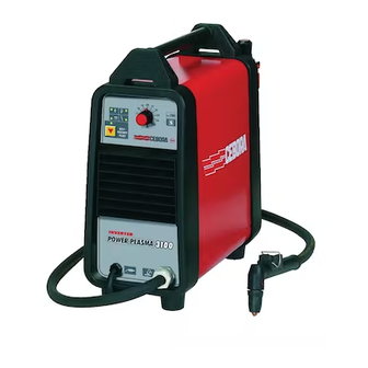
CEBORA S.p.A. 2 - SYSTEM DESCRIPTION 2.1 - Introduction. The POWER PLASMA 3100 is a plasma arc system for cutting electrically conductive materials. It is made up of an electronic power source (art. 296), with built-in torch and trolley for easy movement. - Page 5 CEBORA S.p.A. The HF board (22) also acts as an input and output interface for the torch; the board contains the torch start button circuit and the power anchors for the earth terminals, electrode and nozzle of the torch. The HF board (22) also includes the circuit for switching from pilot arc to transfer arc. It is...
-
Page 6: Maintenance
CEBORA S.p.A. 3 - MAINTENANCE WARNINGS ANY INTERNAL INSPECTIONS OR REPAIRS MUST BE CARRIED OUT BY QUALIFIED PERSONNEL. UNPLUG THE UNIT FROM THE POWER MAINS AND WAIT FOR THE INTERNAL CAPACITORS TO DISCHARGE (6 MINUTES) BEFORE PERFORMING MAINTENANCE. 3.1 - Periodic inspection, cleaning. -
Page 7: Power Source Operation
CEBORA S.p.A. 3.2.2 - Power source operation. NOTE Operations preceded by this symbol refer to operator actions. ♦ Operations preceded by this symbol refer to machine responses that must occur following an operator action. System shut off and disconnected from the mains. - Page 8 CEBORA S.p.A. Correct? NO (see 3.3.5, 3.3.6, 3.3.7 and 3.3.8). With pilot arc lit, place the torch near the workpiece. ♦ Begin cutting. Adjust the knob (M) to the current level suited to the kind of cutting. Correct? NO (see 3.3.9).
-
Page 9: Troubleshooting
CEBORA S.p.A. 3.3 - Troubleshooting. WARNINGS ANY INTERNAL INSPECTIONS OR REPAIRS MUST BE CARRIED OUT BY QUALIFIED PERSONNEL. BEFORE REMOVING THE PROTECTIVE GUARDS AND ACCESSING INTERNAL PARTS, DISCONNECT THE POWER SOURCE FROM THE MAINS AND WAIT FOR THE INTERNAL CAPACITORS TO DISCHARGE (6 MINUTES). - Page 10 CEBORA S.p.A. switch (9) and terminal IN2 of filter board (36). Replace the choke (17) if necessary. ♦ Check the mains voltage conditions. MAINS VOLTAGE RECOGNITION TEST. Power board (35), terminals + (+) and - (-) of the rectifier bridge W1 = approximately +320 Vdc, with both mains voltages (115 Vac or 230 Vac), 3 seconds after closing the switch (9), thus after the mains voltage selection phase.
-
Page 11: Power Source Powered, Control Panel On, Fan (15) Stopped
CEBORA S.p.A. 3.3.2 - Power source powered, control panel on, fan (15) stopped. FAN (15) TEST. Fan (15) fast-on terminals = 115 Vac (with mains 115 Vac) or 230 Vac (with mains 230 Vac) in the first 3 seconds after closing the switch (9), thus during the mains voltage selection phase;... -
Page 12: The Start Button Produces No Effect
CEBORA S.p.A. 3.3.4 - The start button produces no effect. WARNING FOR THE FOLLOWING TESTS DISCONNECT THE CONNECTOR J3 ON THE HF BOARD (22) TO PREVENT HIGH FREQUENCY FROM BEING GENERATED. START COMMAND TEST. Panel board (31), connector CN2 terminals 4 (+) and 5 (-) = approximately +14 Vdc, with start button on torch released;... -
Page 13: No Gas Flows From The Torch
CEBORA S.p.A. 3.3.5 - No gas flows from the torch. SOLENOID VALVE (20) TEST. Solenoid valve (20) terminals = +230 Vac with torch button pressed (with mains at either 115 or 230 Vac). The solenoid valve opening time depends on the post-gas time and testing conditions. -
Page 14: Gas Flows From The Torch, The Pilot Arc Does Not Light (High Frequency Missing)
CEBORA S.p.A. 3.3.6 - Gas flows from the torch, the pilot arc does not light (high frequency missing). NOTE Some of the following tests may be checked only in the second after pressing the torch start button, due to failure by the pilot arc to strike. - Page 15 CEBORA S.p.A. ♦ With power source off, check the resistance between the terminals J4 of HF board (22) and the patch terminal disconnected from J3 (winding of the transformer TF2 on power board (35)). If the winding is broken, replace the power board (35).
-
Page 16: Gas Flows From The Torch, The Pilot Arc Does Not Light (Nozzle Voltage Missing)
CEBORA S.p.A. 3.3.7 - Gas flows from the torch, the pilot arc does not light (nozzle voltage missing). NOTE Some of the following tests may be checked only in the second after pressing the torch start button, due to failure by the pilot arc to strike. -
Page 17: Irregular Pilot Arc Starts, Unstable Pilot Arc
CEBORA S.p.A. 3.3.8 - Irregular pilot arc starts, unstable pilot arc. PLASMA GAS PRESSURE TEST. Gas pressure in the torch plasma chamber is correct. Correct? ♦ Check for the presence of gas at the supply fitting (B), and make sure that the pressure and air flow in the intake line comply with the specified values (see Instructions Manual and Sales Catalogue). -
Page 18: Transfer Arc Does Not Take Place Or Is Too Weak For Cutting
CEBORA S.p.A. 3.3.9 - Transfer arc does not take place or is too weak for cutting. WARNING Due to lighting the pilot arc and the HF pulses, some instruments may not be suitable for measuring signals in the following tests. Given the delicacy of the measuring points, we... -
Page 19: Alarm Signals
CEBORA S.p.A. 3.4 - Alarm signals. 3.4.1 - Yellow (G) and red (N) leds lit = temperature outside limits. The power source delivers no current, but the fan continues running; we therefore recommend leaving the power source powered to ensure rapid cooling. -
Page 20: Red Led (N) Lit = Power Source Blocked
CEBORA S.p.A. 3.4.3 - Red led (N) lit = power source blocked. This indicator indicates that the power source is in the process of selecting the mains voltage, in the first 3 seconds after closing the switch (9), or, thereafter, is blocked due to a hazardous condition. -
Page 21: Alarms Shown During Pilot Arc Or Transfer Arc (Cutting) Operation
CEBORA S.p.A. - Start button pressed during the reset from stop due to temperature outside limits or low gas pressure. The alarms for high temperature and for low gas pressure cause the power source to stop, and the leds (G) or (L) light together with led (N) on the control panel, but they are not saved. They are automatically reset when the pressure and temperature return to within the allowed limits. -
Page 22: Components List
CEBORA S.p.A. 4 - COMPONENTS LIST 4.1 - Power source art. 296 : see file ESP296.pdf enclosed at the end of the manual. 4.2 - Components table : see file ESP296.pdf enclosed at the end of the manual. 4.3 - Spare parts list. -
Page 23: Electrical Diagrams
CEBORA S.p.A. 5 - ELECTRICAL DIAGRAMS 5.1 - Power source art. 296 : see file SCHE296.pdf enclosed at the end of the manual. 5.2 - Waveforms. 5.2.1 - Open circuit nozzle voltage, interrupted after approximately 300 msec., for missing pilot arc current (par. 3.3.6, 3.3.7, 3.3.8). -
Page 24: Filter Board (36) Code 5.602.078
CEBORA S.p.A. 5.3 - Filter board (36) code 5.602.078. 5.3.1 - Topographical drawing. 5.3.2 - Connector table. Connector Terminals Function IN1 – IN2 115/230 Vac mains power supply input. OUT1 – OUT2 115/230 Vac power supply output for power board (35). - Page 25 CEBORA S.p.A. 5.4.2 - Topographical drawing. 3.302.089 31/05/02...
-
Page 26: Panel Board (31) Code 5.602.124
CEBORA S.p.A. 5.5 - Panel board (31) code 5.602.124. 5.5.1 - Topographical drawing. 5.5.2 - Connector table. Connector Terminals Function +5 Vdc board power supply input. +13,8 Vdc board power supply input. “mains voltage” signal input. relay2 command output (selector switch for 115/230 Vac operation range). -
Page 27: Hf Board (22) Code 5.602.074/C
CEBORA S.p.A. 5.6 - HF board (22) code 5.602.074/C. 5.6.1 - Topographical drawing. 5.6.2 - Connector table. Connector Terminals Function gas solenoid valve (20) relay command input. HF relay command input. board digital circuits 0 Vdc power supply input. 4 – 5 “start”...
Need help?
Do you have a question about the POWER PLASMA 3100 and is the answer not in the manual?
Questions and answers