Vivo DESK-E1L94B Instruction Manual
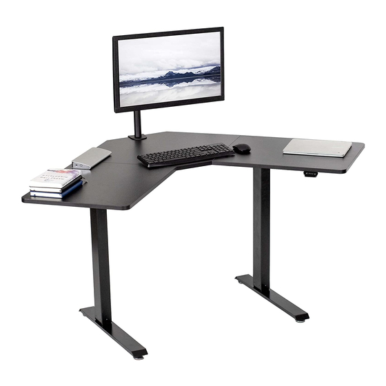
47” x 47” corner electric desk
Hide thumbs
Also See for DESK-E1L94B:
- Instruction manual (9 pages) ,
- Instruction manual (9 pages) ,
- Instruction manual (8 pages)

Subscribe to Our Youtube Channel
Related Manuals for Vivo DESK-E1L94B


Summary of Contents for Vivo DESK-E1L94B
- Page 1 47” x 47” Corner Electric Desk SKU: DESK-E1L94B/C/N/W Instruction Manual Assembly Video & Product Info www.vivo-us.com/products/desk-e1l94b...
- Page 2 7AM - 7PM Monday-Friday Give us a Call: Chat Us: Email Us: 309-278-5303 www.vivo-us.com help@vivo-us.com We’re Here for You! Our customer-minded support team is here for YOU, Monday-Friday 7am-7pm CST. We offer immediate assistance with rapid response times from customer service agents and product techncians to...
-
Page 3: Electrical Safety Instructions
If you do not understand these directions, or if you have any doubts about the safety of the installation, please contact our product support team at 309-278-5303 or help@vivo-us.com for further assistance. Check carefully to make sure there are no missing or defective parts. -
Page 4: Package Contents
Package Contents A (x1) B (x1) C (x1) D (x1) Left Panel Middle Panel Right Panel E (x1) F (x1) G (x1) H (x1) Motorized Leg Left Crossbar Right Crossbar Left Side Bracket I (x1) J (x2) K (x1) L (x1) Right Side Bracket Foot Crossbar... -
Page 5: Included Hardware & Tools
Included Hardware & Tools S-A (x14) S-B (x42) S-C (x8) S-D (x2) M6x11mm Screw ST5x15mm Screw M6x35mm Screw M8x16mm Screw T-A (x1) T-B (x1) 2mm Allen Wrench 5mm Allen Wrench Tools Needed: Weight Capacity: 154lbs (70kg) Phillips Power Level Screwdriver Drill... -
Page 6: Assembly Steps
ASSEMBLY STEPS STEP 1 Connect Left Crossbar (F) to Leg (D), and Right Crossbar (G) to Motorized Leg (E), using M6x11mm Screws (S-A) and 5mm Allen Wrench (T-B). S-A (x4) - Page 7 STEP 2 Attach Left Side Bracket (H) to Leg (D), and Right Side Bracket (I) to Motorized Leg (E) using M6x11mm Screws (S-A) and 5mm Allen Wrench (T-B). S-A (x4)
- Page 8 STEP 3 Attach Feet (J) to Legs (D, E) using M6x35mm Screws (S-C) and 5mm Allen Wrench (T-B). NOTE: Each Foot should be offset and in-line with the side brackets below it. S-C (x8)
- Page 9 STEP 4 Connect Left and Right Crossbars (F,G ) together using Crossbar Connector (K), M6x11mm Screws (S-A), and 5mm Allen Wrench (T-B). S-A (x4)
- Page 10 STEP 5 1). Loosen the nut on Sync Rod (L). 2). Insert the hex rod end into Leg (D). 3). While holding the hex end, pull the larger rod out until the connector engages with Motorized Leg (E). Tighten the set screw on Sync Rod (L) using 2mm Allen Wrench (T-A). 4).
- Page 11 STEP 6 Lay Desktop Panels (A, B, C) upside down on a soft surface. Connect Panels using Connecting Plates (T), ST5x15mm Screws (S-B), and a power drill or Phillips screwdriver. S-B (x16)
- Page 12 STEP 7 1. Align frame assembly with pre-drilled holes on desktop panels. Secure the frame assembly to desktop using ST5x15mm Screws (S-B) and either a power drill or Phillips screwdriver. 2. Attach Shelf Brackets (O) to pre-drilled holes on the back of desktop using ST5x15mm Screws (S-B) and either a power drill or Phillips screwdriver.
- Page 13 STEP 8 1. Connect the Cable (E1) from Motorized Leg (E) and Cable (Q1) from AC Adapter (Q) into the back of Control Panel (P). Plug the AC Adapter into an available wall outlet. 2. Remove the protective film off of Cable Clips (R) and use to organize cables on the underside of desktop, adhering to the desktop panels.
- Page 14 Optional For added stability, Foot Extensions (M) can be added to the back of each Foot (J). To do so, twist and remove the existing Foot Pad (J1). Then, install Foot Extension using M8x16mm Screws (S-D) and 5mm Allen Wrench (T-B). Replace Foot Pads. S-D (x2)
- Page 15 STEP 9 Set desk upright. Hang Shelf (N) on vertical part of Shelf Brackets (O) and secure onto the angled part. Place Grommet Covers (S) into the holes on Middle Panel (B).
-
Page 16: Led Controller
LED CONTROLLER OPERATION LED Panel Displays the current desk height Up Arrow Press and hold to raise the desk. Release when desired height is reached. Down Arrow Press and hold to lower the desk. Release when desired height is reached. Memory Settings Use these settings to save and return to your desired height. -
Page 17: Troubleshooting
If error presists, please contact our Product Support Team at 309-278-5303 or help@vivo-us.com for further assistance Undervoltage Warning: The input voltage is too low. f correct AC adapter is being used, unplug the desk from the wall and disconnect all cables from the controller. - Page 18 WHO WE ARE VIVO is more than a brand of ergonomic office furniture. We are a team of creative and innovative indivuduals working together to offer high quality, affordable ergonomic solutions. We think and work outside of the box to serve...
-
Page 19: Need Assistance
Call Us: 309-278-5303 Average Resolution Time: 5m 4s Chat Us: www.vivo-us.com Average Resolution Time: < 15m Email Us: help@vivo-us.com Average Resolution Time: 1HR 8M 23% within < 15m 38% within <... - Page 20 LAST UPDATED: 04/24/24 REV2.1LF Need Help? Get In Touch Monday-Friday from 7:00am-7:00pm CST help@vivo-us.com www.vivo-us.com 309-278-5303 Chat live with an agent! FOR MORE GREAT VIVO PRODUCTS, CHECK OUT OUR WEBSITE AT: WWW.VIVO-US.COM VIVO-us @vivo_us...
Need help?
Do you have a question about the DESK-E1L94B and is the answer not in the manual?
Questions and answers