Vivo DESK-E1L94B Instruction Manual
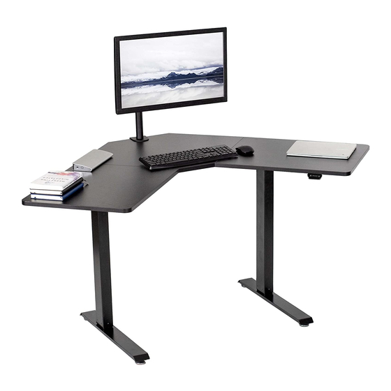
Black 47" x 47" corner electric desk
Hide thumbs
Also See for DESK-E1L94B:
- Instruction manual (21 pages) ,
- Instruction manual (9 pages) ,
- Instruction manual (9 pages)
Advertisement
Quick Links
Black 47" x 47" Corner Electric Desk
Instruction Manual
SKU: DESK-E1L94B
Scan the QR code with your mobile device or follow the link
for helpful videos and specifications related to this product.
https://vivo-us.com/products/desk-e1l94b
GET IN TOUCH | Monday-Friday from 7:00am-7:00pm CST
help@vivo-us.com
www.vivo-us.com
Chat live with an agent!
309-278-5303
Advertisement

Subscribe to Our Youtube Channel
Related Manuals for Vivo DESK-E1L94B


Summary of Contents for Vivo DESK-E1L94B
- Page 1 Black 47" x 47" Corner Electric Desk Instruction Manual SKU: DESK-E1L94B Scan the QR code with your mobile device or follow the link for helpful videos and specifications related to this product. https://vivo-us.com/products/desk-e1l94b GET IN TOUCH | Monday-Friday from 7:00am-7:00pm CST help@vivo-us.com...
-
Page 2: Electrical Safety Instructions
WARNING! If you do not understand these directions, or if you have any doubts about the safety of the installation, please call a qualified technician. Check carefully to make sure there are no missing or defective parts. Improper installation may cause damage or serious injury. -
Page 3: Assembly Steps
WARNING: CHOKING HAZARD SMALL PARTS - NOT FOR CHILDREN UNDER 3 YEARS. ADULT SUPERVISION IS REQUIRED. DO NOT EXCEED WEIGHT CAPACITY. 176lbs Failure to do so may result in serious injury. TOOLS NEEDED (80kg) Phillips Drill Screwdriver ASSEMBLY STEPS STEP 1 Assemble Left Crossbar (F) to Left Leg (K) and Right Crossbar (G) to Right Leg (J) using M8x47mm Screws (S-D) and 5mm Allen Wrench (T-C). - Page 4 STEP 3 Assemble Left Crossbar (F) and Right Crossbar (G) with Crossbar Connector (H) using M6x12mm Screws (S-B) and 4mm Allen Wrench (T-B). STEP 4 Secure Feet (S) to the frame assembly using M6x35mm Screws (S-E) and 5mm Allen Wrench (T-C). Screw Foot Pads (W) into Feet (S).
- Page 5 STEP 5 Insert Anti-Vibration Pads (T) to the frame assembly. Loosen the nut on Sync Rod (D) and insert the hex rod end into Left Leg (K). While holding the hex end, pull the larger rod out until the connector engages with Right Leg (J).
- Page 6 STEP 7 Secure the frame along with Hook (Q) and the brackets from Shelf (I) to the desktop assembly using M5x16mm Screws (S-A) and a Phillips screwdriver. STEP 8 Connect AC Adapter (N) and Control Panel (O) to Motor (P). Secure Control Panel (O) to the desktop using M5x16mm Screws (S-A) and a Phillips screwdriver, then organize cables using Cable Clips (U).
- Page 7 STEP 9 Insert Cable Management Covers (V) into the desktop. Connect Shelf (I) to the brackets. Refer to the controller manual for operation. CAUTION! Do not exceed desk Keep area of vertical Keep weight on desk Leave enough slack in weight limit.
- Page 8 AVG. RESPONSE TIME (within office hrs) - 23% within < 15m - 38% within < 30m - 61% within < 1hr - 83% within < 2hr - 92% within < 3hr FOR MORE VIVO PRODUCTS, CHECK OUT OUR WEBSITE AT: www.vivo-us.com...
Need help?
Do you have a question about the DESK-E1L94B and is the answer not in the manual?
Questions and answers