Advertisement
Quick Links
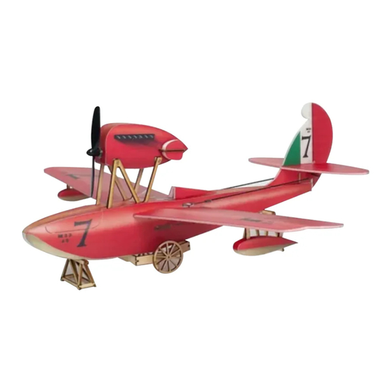
Macchi M-33
Assembly Instructions
Important notification
1.The model is supplied with UFO and 502 glue. UFO is for bonding foam parts, and 502 for
bonding wood, carbon fiber and metal parts. 502 glue will cause serious corrosion to foam parts.
2.Please wait for the glue to dry and solidify in each installation step before the next installation.
3.Please avoid using flame to heat the heat shrinkable tube on the model. Electric iron shall be
used for heating.
4.Please use razor blade to remove the parts from the plate. Do not tear the parts by force.
Advertisement

Related Manuals for MinimumRC Macchi M-33


Summary of Contents for MinimumRC Macchi M-33
- Page 1 Macchi M-33 Assembly Instructions Important notification 1.The model is supplied with UFO and 502 glue. UFO is for bonding foam parts, and 502 for bonding wood, carbon fiber and metal parts. 502 glue will cause serious corrosion to foam parts.
- Page 2 1. Fuselage internals. 2. Bond the plywood structure with CA glue.
- Page 3 3. Connect the servos to a powered receiver. Bind the receiver with your transmitter to make the servos arms return to their neutral point. Test whether the servos are working correctly, and install the servo arms according to the position shown in the pictur e. Note: Please make sure that the servos have been tested and installed in strict accordance with the following picture.
- Page 4 5. Connect the receiver to the servos. Test whether the corresponding relationship between the three servos and the transmitter channel is correct. Fix the receiver with Velcro and tie the cable s. 6. Bend the front part of the two fuselage side panels inward as shown in the figure. See steps 7 -8 for the method.
- Page 5 8. Press the position where the part needs to be bent on the edge corner of the desktop, keep the palm close to the part, and slide down. 9. Fuselage parts bended. 10. Install the fuselage baffle.
- Page 6 11. Align the marking line on the inside of the fuselage and fix the wooden framework with glue. 12. Press the top plate and bottom plate of the fuselage and bend them into the corresponding shape. Fix the top plate and bottom plate of the fuselage with glue. 13.
- Page 7 14. Fix the top and bottom strip of the fuselage with glue. 15. Combine the fuselage. 16. Paste the fuselage stickers.
- Page 8 17. Cut off the connection position of the hatch cover so that it can be opened forward. When the hatch cover is closed, it is fixed by the end of the sticker. 18. Apply glue at the bottom of the engine compartment bracket and insert them into the fuselage.
- Page 9 19. Cockpit ridge. 20. Use a sharp tool (screwdriver) to score through the half-cut lines on the bottom surface of the part so that it can bend inward. 21. Install the cockpit ridge.
- Page 10 22. Wind shield. 23. Insert the locating pin at the root of the cockpit windshield into the reserved installation slot on the fuselage and fix it. 24. Use the end of a screw driver to score through the half-cut line of the vertical tail.
- Page 11 25. Use the end of a screw driver to score through the half-cut line of the horizontal tail. 26. Tail parts. 27. Fix the support column at the root of the vertical tail.
- Page 12 28. Install the vertical tail root. 29. Install the horizontal tail and the main body of the vertical tail. 30. Use a sticker to connect the root of the vertical tail to the rudder.
- Page 13 31. Use the end of a screw driver to score through the half-cut line of the wing surface. 32. Use the end of a screw driver to score through the half-cut line of the aileron. 33. Stick a carbon fiber rod at the bottom of the wing along the notch to increase the strength.
- Page 14 34. Install the wings. 35. Combine the pontoon support and pontoon side plates, and paste the stickers. 36. Align the pre-engraved positioning line at the bottom of the wing and fix the pontoons.
- Page 15 37. Install the aileron control horns. 38. Install the elevator control horn. 39. Install the rudder control horn.
- Page 16 40. Use heat shrinkable tube to connect tail push rod and steel wire clip. 41. Use heat shrinkable tube to connect the pu sh rod and wire clip, then use glue to fix them. 42. Attach the steel wire hooks to the control horns.
- Page 17 43. Attach the pushrods to the servo arms. 44. Cut the carbon rod to proper length and connect the wire hooks with heat shrinkable tubes. 45. Use heat shrinkable tube to connect aileron push rod and steel wire clip.
- Page 18 46. Attach the steel wire clips to the aileron servo arms. 47. Connect the steel wire hooks and wire clips with heat shrinkable tubes. 48. Engine compartment substructure structural components.
- Page 19 49. Combined engine compartment base. Pay attention to the installation direction of the four fasteners. 50. Motor bracket. 51. Install the motor.
- Page 20 52. Install the radiator bracket. 53. Combined engine compartment side panel and frame. 54. Press the top and bottom plates of the engine compartment and fix them along the contour of the engine compartment.
- Page 21 55. Merge the side panel on the other side of the engine compartment, paste the engine compartment sticker, and install the propeller. 56. The motor wire passes through the reserved hole at the bottom of the engine compartment. 57. Combined the radiators.
- Page 22 58. Install the radiators. 59. Use M1.2X6 screws to fix the engine compartment. 60. Details: open a hole at the root of the bracket, thread the motor wire into the fuselage and connect it to the receiver.
- Page 23 61. The battery is placed in the cabin. Assembly complete!
-
Page 24: Maiden Flight
Maiden flight ·The center of gravity of the aircraft is located at the front score line of the wing. ·The active range of ailerons, elevator and rudder is 5mm on both sides. ·choose grass land for maiden flight.
Need help?
Do you have a question about the Macchi M-33 and is the answer not in the manual?
Questions and answers