Table of Contents
Advertisement
Available languages
Available languages
Quick Links
IN240100023V01_UK_FR_DE_ES_IT
370-061V00
9-60
9-60
9-60
9-60
9-60
EN_IMPORTANT, RETAIN FOR FUTURE REFERENCE: READ CAREFULLY.
FR_IMPORTANT: A LIRE ATTENTIVEMENT ET A CONSERVER POUR VOUS Y REFRERER
ULTERIEUREMENT
ES_IMPORTANTE, LEA DETENIDAMENTE Y GUARDE PARA FUTURAS REFERENCIAS.
DE_WICHTIG! SORFGFÄLTIG LESEN UND FÜR SPÄTERES NACHSCHLAGEN AUFBEWAHREN.
IT_IMPORTANTE, LEGGERE E CONSERVARE QUESTO MANUALE D'ISTRUZIONE PER UN USO
FUTURO.
Advertisement
Table of Contents

Related Manuals for HOMCOM 370-061V00


Summary of Contents for HOMCOM 370-061V00
- Page 1 IN240100023V01_UK_FR_DE_ES_IT 370-061V00 9-60 9-60 9-60 9-60 9-60 EN_IMPORTANT, RETAIN FOR FUTURE REFERENCE: READ CAREFULLY. FR_IMPORTANT: A LIRE ATTENTIVEMENT ET A CONSERVER POUR VOUS Y REFRERER ULTERIEUREMENT ES_IMPORTANTE, LEA DETENIDAMENTE Y GUARDE PARA FUTURAS REFERENCIAS. DE_WICHTIG! SORFGFÄLTIG LESEN UND FÜR SPÄTERES NACHSCHLAGEN AUFBEWAHREN.
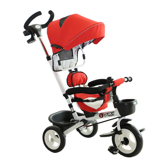
- Page 6 13 14 15 1. Front wheel 13.foot-pad 2. Screw for Front fork 14.direction control system 3. Front fork 15.twist for seat 4. Fender 16.pushbar 5. Main frame 17.cup holder 6.Front basket 18.backrest 7.Screw for handlebar 19.saddle 8.cap of handlebar screw front 20.fixing knob for rear basket 9.bell 21.rear basket...
- Page 7 1.As shown in the picture, insert the rear wheel 2.As shown 3.As shown axle into the main frame rear dropout, gently picture, front picture, first insert the tap until it locks with a "click" sound. fender to the front fork headset into the front fork with screws...
- Page 8 6.As shown in the picture, place the seat bracket 7.As shown in the picture, first unscrew the seat onto the frame. fixing knob from the bolt, then let the bolt below the saddle pass through the hole on the main frame, then tighten the seat fixing knob until the saddle is secure and doesn't move.
-
Page 9: Nom Des Pièces
Nom des pièces 13 14 15 11. Ensemble de la roue avant 13. Repose-pieds avant 2. Vis de fixation de la fourche avant 14. Tige de direction 3. Fourche avant 15. Bouton de fixation du siège 4. Garde-boue 16. Pousser la tige 5. -
Page 10: Installation
Installation 1. Comme indiqué sur l'image, insérez l'axe de 2. Comme indiqué sur 3. Comme indiqué sur la roue arrière dans l'orifice de fixation de la l'image, fixez l'image, insérez d'abord roue arrière du cadre principal, tapotez légère- garde-boue avant sur la potence dans ment jusqu'à... - Page 11 6. Comme indiqué sur l'image, placez le support 7. Comme indiqué sur l'image, dévissez d'abord de selle sur le cadre. le bouton de fixation de la selle de l'écrou, puis faites passer la vis sous la selle à travers le trou du cadre principal, puis serrez le bouton de fixation de la selle jusqu'à...
- Page 12 Teilebezeichnung 1. Vorderradbau 13. Vorderfußstütze 2. Befestigungsschrauben der Vorderradgabel 14. Lenkstange 3. Vorderradgabel 15. Sitzbefestigungsknopf 4. Spritzschutz 16. Schubstange 5. Hauptrahmen 17. Flaschenhalter 6. Vordere Ablage 18. Rückenlehne 7. Lenkerbefestigungsschrauben 19. Sitzkissen 8. Vorderabdeckung 20. Hinterer Korb Befestigungsknopf 9. Klingel 21.
- Page 13 Aufstellung 1. Wie auf dem Bild gezeigt, stecken Sie die 2. Wie auf dem Bild 3. Wie auf dem Bild Hinterachse in die Hinterradhalterung des gezeigt, befestigen Sie gezeigt, stecken Hauptrahmens ein, tippen Sie leicht darauf, bis Schutzblech zuerst den Vorbau in die es mit einem "Klick"...
- Page 14 6. Wie auf dem Bild gezeigt, legen Sie die Sattel- 7. Wie auf dem Bild gezeigt, drehen Sie zuerst halterung auf den Rahmen. die Befestigungsschraube vom Bolzen ab, lassen Sie dann den Bolzen unter dem Sattel durch das Loch im Hauptrahmen passieren und ziehen Sie anschließend die Befestigungss- chraube fest, bis der Sattel nicht mehr wackelt.
-
Page 15: Nome Delle Parti
Nome delle parti 13 14 15 1. Assemblea ruota anteriore 13. Poggiapiedi anteriore 2. Viti di fissaggio forcella anteriore 14. Asta di sterzo 3. Forcella anteriore 15. Pomello di fissaggio sella 4. Parafango 16. Asta di spinta 5. Telaio principale 17. -
Page 16: Installazione
Installazione 1. Come mostrato in figura, inserisci l'asse 2. Come mostrato in 3. Come mostrato in della ruota posteriore nell'incavo della ruota figura, fissa il parafango figura, inserisci per prima posteriore del telaio principale, picchiettando anteriore alla forcella la testa di guida nella leggermente fino a sentirlo bloccarsi con un anteriore con le viti (la forcella anteriore e fissa-... - Page 17 6. Come mostrato in figura, posiziona il supporto 7. Come mostrato in figura, svita prima il pomello della sella sul telaio. di fissaggio della sella dal bullone, quindi fai pas- sare il bullone sotto la sella attraverso il foro nel telaio principale, quindi stringi il pomello di fissaggio della sella fino a quando la sella non si muove.
-
Page 18: Nombre De Las Piezas
Nombre de las piezas 13 14 15 1. Componente de la rueda delantera 13. Reposapiés delantero 2. Tornillos de fijación de la horquilla delantera 14. Barra de dirección 3. Horquilla delantera 15. Perilla de fijación del asiento 4. Guardabarros 16. Varilla de empuje 5. -
Page 19: Instalación
Instalación 1. Como se muestra en la imagen, inserta el 2. Como se muestra en 3. Como se muestra en eje de la rueda trasera en el agujero de inser- la imagen, fija el guard- la imagen, primero inser- ción de la rueda trasera del marco principal, abarros delantero en la ta el espaciador en la golpea suavemente hasta que encaje con un... - Page 20 6. Como se muestra en la imagen, coloca la 7. Como se muestra en la imagen, primero base de fijación del asiento en el marco. desenrosca el perno del botón de fijación del asiento en el perno, luego permite que el perno debajo del asiento pase a través del agujero en el marco principal, luego aprieta el perno del botón de fijación del asiento hasta que el asiento...
Need help?
Do you have a question about the 370-061V00 and is the answer not in the manual?
Questions and answers