Table of Contents
Advertisement
Available languages
Available languages
Quick Links
Children tricycle/Tricycle pour enfants/ Kinder-dreirad/
Triciclo infantil /Triciclo para crianças/Triciclo per bambini
EN_WARNING: Certification Age: 18+ months; Max weight: 25 kg.
DE_WARNUNG: Zertifizierungsalter: 18+ Monate; Max. Gewicht: 25 kg.
FR_ATTENTION: Âge de certification: 18+ mois; Poids maximum: 25 kg.
ES_ADVERTENCIA: Edad de certificación: 18+ meses; Peso máximo: 25 kg.
PT_AVISO: Idade de certificação: 18+ meses; Peso máximo: 25 kg.
IT_ATTENZIONE: Età di certificazione: 18+ mesi; Peso massimo: 25 kg.
EN_IMPORTANT, RETAIN FOR FUTURE REFERENCE: READ CAREFULLY.
FR_IMPORTANT:A LIRE ATTENTIVEMENT ET À CONSERVER POUR CONSULTATION
ULTÉRIEURE.
ES_IMPORTANTE, LEA Y GUARDE PARA FUTURAS REFERENCIAS.
PT_IMPORTANTE, RETER PARA REFERÊNCIA FUTURA: LEIA ATENTAMENTE.
DE_WICHTIG! SORGFÄLTIG LESEN UND FÜR SPÄTER NACHSCHLAGEN AUFBEWAHREN.
IT_IMPORTANTE! CONSERVARE IL PRESENTE MANUALE PER FUTURO RIFERIMENTO E
LEGGERLO ATTENTAMENTE.
IN230400403V01_UK_FR_DE_ES_PT_IT
370-025
Advertisement
Table of Contents

Related Manuals for HOMCOM 370-025


Summary of Contents for HOMCOM 370-025
- Page 1 IN230400403V01_UK_FR_DE_ES_PT_IT 370-025 Children tricycle/Tricycle pour enfants/ Kinder-dreirad/ Triciclo infantil /Triciclo para crianças/Triciclo per bambini EN_WARNING: Certification Age: 18+ months; Max weight: 25 kg. DE_WARNUNG: Zertifizierungsalter: 18+ Monate; Max. Gewicht: 25 kg. FR_ATTENTION: Âge de certification: 18+ mois; Poids maximum: 25 kg.
-
Page 2: Maintenance And Care
ATTENTION Read all instructions in this manual before using. It explains how to assemble and use the tricycle safely, preventing damage to the product or personal injury. WARNING: 1.CHOKING HAZARD—Small parts. 2. This product must be installed by an adult. Keep children away. 3. -
Page 3: Entretien Et Maintenance
ENTRETIEN ET MAINTENANCE A. Conservez toutes les instructions et les pièces relatives à ce produit pour pouvoir vous y référer ultérieurement. B. Vérifiez régulièrement que le produit n'est pas endommagé et que toutes les vis sont bien serrées. C. Vérifier que le siège est bien fixé. D. -
Page 4: Mantenimiento Y Cuidado
ATENCIÓN Lea todas las instrucciones antes de utilizar el triciclo. Le dirá cómo utilizarlo y montarlo correctamente para evitar causar daños al triciclo o provocar lesiones corporales. ADVERTENCIA: 1. PELIGRO DE ASFIXIA: Incluidas piezas pequeñas. No es adecuado para los niños menores de 3 años. -
Page 5: Manutenção E Cuidados
ATENÇÃO Por favor leia as instruções antes de usar. Elas indicarão como utilizar e montar o triciclo, para evitar danificar o produto e causar lesões. ADVERTÊNCIA: 1. PERIGO DE ASFIXIA - Pequenas peças. 2. Só é permitida a instalação por adultos, manter as crianças afastadas. 3. - Page 6 ATTENZIONE si prega di leggere le istruzioni prima dell'uso. Esse spiegheranno come utilizzare e montare il triciclo, per evitare di danneggiare il prodotto e procurarsi lesioni personali. AVVERTENZA: 1. RISCHIO DI SOFFOCAMENTO — Parti piccole. 2. Consentire l'installazione solo agli adulti, tenere lontani i bambini. 3.
-
Page 7: Name Of Parts
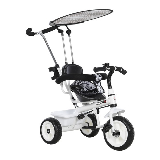
NAME OF PARTS 1. Front wheel assembly; 2. Front fork fixing screws; 3. Front fork; 4. Fender; 5. Main frame; 6. Front basket; 7. Handlebar fixing screws; 8. Front dome; 9. The bell; 10. Handlebars; 11. bumper; 12. Awning; 13. Parent pushbar; 14. -
Page 8: Installation
INSTALLATION 1. As shown in the figure: 2. As shown in the figure: - Insert the rear axle into the rear wheel jack - Insert the front fork's of the main frame. Tap gently until the bead connection into the front fork lock clicks into place. - Page 9 IMPORTANT: The seat cushion is adjustable. 1 is the front file; 2 is the rear stop. The bolt holes indicated by 2 can expand the riding space. 5. As shown in the figure: 6. As shown in the figure: - Align the seat with the holes on the - Attach the basket to the rear axle of the frame, then secure it with screws.
-
Page 10: Nom Des Pièces
NOM DES PIÈCES 1. Assemblage de la roue avant; 2. Vis de fixation de la fourche avant ; 3.Fourche avant; 4.Garde-boue; 5. Châssis principal; 6. Panier avant; 7.Vis de fixation du guidon; 8. Dôme avant; 9. Cloche; 10. Guidon; 11. Cadre ; 12. - Page 11 INSTALLATION 1. Comme indiqué sur la figure: 2. Comme indiqué sur la figure: - Insérez l’essieu arrière dans le cric de roue - Insérez la béquille dans le tube arrière du châssis principal. Tapotez de fourche avant. doucement jusqu’à ce que le verrou du - Verrouillez-le en place à...
- Page 12 IMPORTANT: Le coussin du siège est réglable. 1 est la butée avant ; 2 est la butée arrière. Les trous de boulon indiqués par 2 peuvent agrandir l’espace de conduite. 5. Comme indiqué sur la figure : 6. Comme indiqué sur la figure : - Aligner le siège avec les trous sur le - Fixer le panier à...
- Page 13 TEILEBEZEICHNUNG 1. Montage des Vorderrads; 2. Befestigungsschrauben für die Vordergabel; 3. Vorderradgabel; 4. Schutzblech; 5. Hauptrahmen; 6. Vorderer Korb; 7. Befestigungsschrauben für den Lenker; 8. Vordere Endkappe; 9. Die Klingel; 10. Lenker; 11. Rahmen; 12. Sonnenschutz; 13. Drücken Sie den Lenker; 14.
- Page 14 INSTALLATION 1. Wie in der Abbildung gezeigt: 2. Wie in der Abbildung gezeigt: - Stecken Sie die Hinterachse in die - Stecken Sie den Ständer in Hinterradaufnahme des Hauptrahmens. das Rohr der Vordergabel. Klopfen Sie leicht, bis die Sperre einrastet. - Verriegeln Sie ihn unter Verwendung der Befestigungsschraube der...
- Page 15 WICHTIG: Das Sitzpolster ist verstellbar. 1 ist die vordere Reihe; 2 ist der hintere Anschlag. Die mit 2 angezeigten Bolzenlöcher können den Fahrbereich erweitern. 5. Wie in der Abbildung gezeigt: 6. Wie in der Abbildung gezeigt: - Richten Sie den Sitz an den Löchern - Befestigen Sie den Korb an der des Rahmens aus und befestigen Sie hinteren Achse des Hauptrahmens.
-
Page 16: Nomi Dei Componenti
NOMI DEI COMPONENTI 1. Ruota anteriore; 2. Viti di fissaggio della forcella anteriore 3. Forcella anteriore; 4. Parafango; 5. Telaio principale; 6. Cesto anteriore; 7. Viti di fissaggio del manubrio; 8. Cupolina anteriore; 9. Campanello; 10. Manubrio; 11. Struttura di protezione; 12. - Page 17 MONTAGGIO 1.Come mostrato nella figura: 2.Come mostrato nella figura: - inserire l'asse posteriore nel supporto della - Inserire il pedale nel tubo della ruota posteriore del telaio. forcella anteriore Battere delicatamente finché la testina di - Bloccarlo in posizione con la blocco non scatta in posizione.
- Page 18 IMPORTANTE: Il cuscino del sedile è regolabile. L’1 è fissaggio anteriore; IL 2 è fissaggio posteriore. I fori dei bulloni indicati da 2 possono ampliare lo spazio di guida. 5. Come mostrato nella figura: 6. Come mostrato nella figura: - Allineare il sedile con i fori sulla - Fissare la vaschetta all'asse struttura, e fissarlo con le viti.
- Page 19 PARTES 1. Ruedas delanteras; 2. Tornillos fijación horquilla delantera; 3. delantera; 4. Guardabarros; 5. Cuadro principal; 6. Cesta delantera; 7. Tornillos fijación del manillar; 8. Cúpula delantera; 9. Timbre; 10. Manillar; 11. Cuadro; 12. Toldo; 13. Asa de empuje; 14. Asiento trasero; 15.
-
Page 20: Instalación
INSTALACIÓN 1. Como se muestra en la figura: 2. Como se muestra en la figura: - Inserte el eje trasero en la rueda trasera del - Introduzca el caballete en el bastidor principal. Golpee suavemente tubo de la horquilla delantera. hasta que el bloqueo del talón encaje en su - Fíjelo con el tornillo de fijación sitio. - Page 21 IMPORTANTE: Cojín del asiento es regulable. 1 es el file delantero; 2 es el tope trasero. Los orificios para pernos indicados por 2 pueden ampliar el espacio de conducción. 5. Como se muestra en la figura: 6. Como se muestra en la figura: - Alinee el asiento con los orificios del - Fije la cesta al eje trasero del bastidor marco y fíjelo con tornillos.
-
Page 22: Nome Das Partes
NOME DAS PARTES 1. Roda dianteira; 2. Parafusos de fixação da forquilha; 3. Forquilha dianteira; 4. Pára-lamas; 5. Estrutura principal; 6. Cesto dianteiro; 7. Parafusos de fixação do guiador; 8. Cúpula dianteira; 9. Sineta; 10. Guiador; 11. Estrutura de proteção; 12. - Page 23 INSTALAÇÃO 1. Como indica a figura: 2. Como indica a figura: - Insira as rodas traseiras no eixo traseiro da - Inserir a forquilha dianteira no estrutura principal. Aperte suavemente até encaixe correspondente da as rodas encaixarem-se no lugar. roda dianteira. - Fixe-a com parafusos e porcas, como mostra a figura.
- Page 24 IMPORTANTE: A almofada do assento é regulável. 1 é o orifício dianteiro; 2 é o orifício traseiro. Os orifícios dos parafusos indicados por 2 podem alargar o espaço de condução. 5. Como indica a figura: 6. Como indica a figura: - Alinhe o assento com os orifícios da - Fixe o cesto ao eixo traseiro da estrutura e, em seguida, fixe-o com...
Need help?
Do you have a question about the 370-025 and is the answer not in the manual?
Questions and answers