Table of Contents
Advertisement
Quick Links
Installation, Operating &
Maintenance Instructions
Large transfer valve TwinVAT
with double acting pneumatic actuator
Series 061
100 × 1000 mm (3.94" × 39.37") to
300 × 3800 mm (11.81" × 149.61")
This manual is valid for the following product ordering numbers:
For all 0610X- with a double opening (double TwinVAT)
906832EB.DOCX
Edition 2019-04-08
Advertisement
Table of Contents
Troubleshooting

Subscribe to Our Youtube Channel
Related Manuals for VAT 061 Series


Summary of Contents for VAT 061 Series
- Page 1 Installation, Operating & Maintenance Instructions Large transfer valve TwinVAT with double acting pneumatic actuator Series 061 100 × 1000 mm (3.94" × 39.37") to 300 × 3800 mm (11.81" × 149.61") This manual is valid for the following product ordering numbers: For all 0610X- with a double opening (double TwinVAT) 906832EB.DOCX Edition 2019-04-08...
- Page 2 VAT. Offenders are liable to pay damages. The original VAT firmware and updated state of the art versions of the VAT firmware are intended for use with VAT products. The VAT firmware contains a limited, time unlimited user license.
-
Page 3: Table Of Contents
Series 061 Contents Description of product ................ 5 Identification of product..................5 Use of product ....................5 Related documents..................5 Important information ..................6 Technical data ....................6 Common labeling for interfaces and position indicators ........6 Safety ....................7 Compulsory reading material ................ - Page 4 Series 061 Dismounting ....................40 Storage ......................40 Packaging and Transport ..............41 Packaging ..................... 42 Transport ...................... 42 Disposal ..................... 43 Spare parts ..................44 4/44 Edition 2019-04-08 906832EB.DOCX...
-
Page 5: Description Of Product
A - ..Order number Use of product Use product for clean and dry vacuum applications only. Other applications are only allowed with the written permission of VAT. Related documents • Product data sheets • IOMI of valve options •... -
Page 6: Important Information
Technical specification on parts from third-party suppliers Product may get damaged. Regardless of specification on parts from third-party suppliers, the product only must be operated according the technical details in the VAT product data sheet. See product data sheet, dimensional drawing and design specification customer chamber. -
Page 7: Safety
Series 061 SAFETY Safety Compulsory reading material Read this chapter prior to performing any work with or on the product. It contains important information that is significant for your own personal safety. This chapter must have been read and understood by all persons who perform any kind of work with or on the product during any stage of its serviceable life. -
Page 8: Personnel Qualifications
SAFETY Series 061 Personnel qualifications WARNING Unqualified personnel Inappropriate handling may cause serious injury or property damage. Only qualified personnel are allowed to carry out the described work. Safety labels Label Part No. Location on valve On the protective foils T-9001-156 covering the valve openings Top, bottom &... -
Page 9: Design And Function
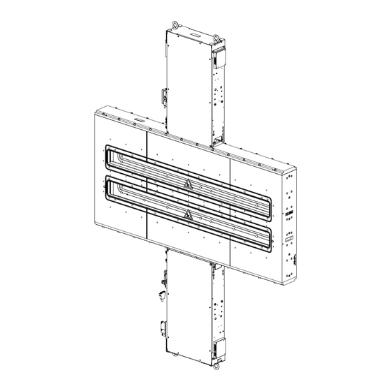
Series 061 DESIGN AND FUNCTION Design and Function Design Valve body Valve gates (2×) Pneumatic actuator (vertical) Identification plate Control unit (option) Solenoid valves (option) Pumping and vent port (option) Actuator flange Pressure gauge port (option) 10 Body cover Figure 3-1 906832EB.DOCX Edition 2019-04-08 9/44... -
Page 10: Function
DESIGN AND FUNCTION Series 061 Function The vertical pneumatic actuator moves the gates to the open or retracted closed position. The horizontal actuator moves the gates from the retracted open position to the extended closed and pneumatically locked position. Leak tightness of the closed valve gates is ensured by a homogeneous O-ring compression through the horizontal actuator and through a differential pressure on the gate in close direction. -
Page 11: Installation
• Make sure that the supplied products are in accordance with your order. • Inspect the quality of the supplied products visually. If it does not meet your requirements, please contact VAT immediately. • Store the original packaging material. It may be useful if products must be transported or returned to VAT. - Page 12 INSTALLATION Series 061 Fasten the lifting ropes at the two lifting points (1); see «Figure 4-1». The ropes must be in an angle of 90° while lifting the valve. Another angle could cause deformation to the valve. Angle 90° Lifting device (not included) 254408;...
-
Page 13: Installation Into The System
Never actuate the valve before it is installed! For proper operation, the valve needs stability that is only ensured when it is impeccably mounted between two chambers or between two test flanges which are supplied or approved by VAT. Disregarding this instruction will cause damage to the valve body. NOTICE Contamination Product may get contaminated. - Page 14 INSTALLATION Series 061 Remove protective foil from the valve. Remove screw (1) with an allen wrench size 6 from transportation safety devices (2) of the upper opening; see «Figure 4-2». Remove 4 × red plastic transportation safety devices that hold the gate on its place from the upper opening (2);...
- Page 15 Series 061 INSTALLATION NOTICE Sensitive product Pay extra care for securing the smooth lowering of the gated of the upper opening while lifting the valve to upright position. When the valve is in upright position, remove 4x red plastic transportation safety devices that hold the gate on its place from the lower opening (2);...
-
Page 16: Electrical Connection
INSTALLATION Series 061 Electrical connection NOTICE Wrong voltage Electrical components may get damaged. Supply electrical components with the correct voltage. 4.3.1 Electrical connection with control unit Verify valve type on the identification plate; see chapter «1.1 Identification of product». Ordering number: 061..-..49 with solenoid valves and with control unit Connect control unit according to the product data sheets. -
Page 17: Compressed Air Connection
Series 061 INSTALLATION Compressed air connection WARNING Valve in open position Risk of injury when compressed air is connected to the valve. Connect compressed air only when: – valve is installed in the vacuum system – moving parts cannot be touched Use clean, dry or slightly oiled air only. -
Page 18: Initial Operation
VAT. Disregarding this instruction will cause damage to the valve body. In order to ensure leak tightness of the valve, it’s essential to carry out one cycle (open and close movement). - Page 19 Series 061 INSTALLATION Open movement Operate the vertical shaft into the retracted position while both gates are retracted. Movement Command/Verify Comment Check valve Horizontal release (CVHR). Command horizontal cylinders into open position •open horizontal cylinders (ACHO) and release air from the horizontal close Horizontal cylinders (ACHC).
- Page 20 INSTALLATION Series 061 Close movement Operate the gates into the extended position while the vertical shaft is fully extended. Movement Command/Verify Comment Verify that horizontal cylinders are open and that both gates are retracted (PIHO). •Verify valve position Vertical close Command vertical cylinders into close position (ACVC) and release air from the vertical open •close vertical cylinder...
-
Page 21: Operation
Technical specification on parts from third-party suppliers Product may get damaged. Regardless of specification on parts from third-party suppliers, the product only must be operated according the technical details in the VAT product data sheet. NOTICE Operation of the valve Product will get damaged. -
Page 22: Trouble Shooting
Contamination or Check flange seals – unfastened flange connection? Contamination or Check pumping unfastened pumping – flange seals flange connection Leak at valve Leak at bellows or shaft Contact VAT www.vatvalve.com body feedthrough? Table 5-1 22/44 Edition 2019-04-08 906832EB.DOCX... -
Page 23: Control Unit Trouble Shooting
Series 061 OPERATION 5.5.1 Control unit trouble shooting The status of the valve controller is communicated by signals as stated below. In case of malfunctioning of the valve the control unit signals indicate a specific status which can be used to trouble shoot the valve. The table below displays the possible signal combinations. Valve Valve Gate... -
Page 24: Maintenance
Keep human body parts away from movable parts. Maintenance intervals If the valve is operated under clean conditions, VAT recommends replacing the gate O-ring as specified in the product data sheet; see chapter «6.4 Replacement of gate O-ring via actuator flange (actuator down)» or «6.5 Replacement of gate O-ring via actuator flange (actuator up)». -
Page 25: Required Tools
Series 061 MAINTENANCE Required tools • Allen wrench size 5 (M6) • Torque wrench 9 Nm • Slotted screwdriver size 1 • Cleanroom wiper soaked with alcohol (2% methyl ethyl ketone) • O-ring removal tool; see «Figure 6-1» and «Table 11-1» •... -
Page 26: Service Operations
MAINTENANCE Series 061 Service operations 6.3.1 Service position 1 In service position 1 the vertical cylinders are in close position and the horizontal cylinders are in open position. For the double TwinVAT product configuration, Service Position 1 is used for replacing the gate of the upper valve insert. 1 Gate to service 2 Chamber 3 Horizontal actuator... -
Page 27: Service Position 3 - Not Applicable For This Product Configuration
Series 061 MAINTENANCE For more details how to command the valve in service position 2, please see the product data sheet with pneumatic diagram and control sequences 6.3.3 Service position 3 – not applicable for this product configuration! NOTICE Service position 3 is not applicable for this product configuration! 906832EB.DOCX Edition 2019-04-08 27/44... -
Page 28: Replacement Of Gate O-Ring Via Actuator Flange (Actuator Down)
Disconnect compressed air supply. Disconnect electrical power supply. • Mount supporting device (A) (not supplied by VAT) for dismounting the valve insert only at the designated points; see «Figure 6-2» on page 29. • Weight of valve insert, see product data sheet. - Page 29 Series 061 MAINTENANCE Lower valve insert (4) with supporting device; see «Figure 6-2». Actuator flange Washer Screw Valve insert Guidance Supporting device Figure 6-2 Place valve insert on an even and clean surface. Clean 4× guidance (5) if required Remove O-ring (7) with O-ring removal tool; see «Figure 6-1» on page 25. Begin at the indicated access point (X);...
- Page 30 13. Clean sealing surface of actuator flange and O-ring of valve body, use cleanroom wiper. 14. Reassemble the valve. VAT recommends replacing the screws on the actuator flange and / or body cover; see chapter «11 Spare parts». 15. Tighten screws (3) with a torque of 9 Nm; see «Figure 6-2».
-
Page 31: Replacement Of Gate O-Ring Via Actuator Flange (Actuator Up)
Series 061 MAINTENANCE Replacement of gate O-ring via actuator flange (actuator up) WARNING Heavy weight Physical overstraining. Use a crane to lift the product. NOTICE Suspended load Product may get damaged when colliding with solid objects. Assistant staff should help each other when carrying out the work. NOTICE Contamination Product may get contaminated. - Page 32 MAINTENANCE Series 061 Lifting rope Lifting point for M8 eyebolt Screw Washer Actuator flange Guidance Valve insert Figure 6-4 Place valve insert on an even and clean surface. Clean 4× guidance (6) if required. 10. Perform steps 9 to 14 in chapter «6.4 Replacement of gate O-ring via actuator Flange». 11.
-
Page 33: Replacement Of Gate Via Actuator Flange (Actuator Down)
Series 061 MAINTENANCE Replacement of gate via actuator flange (actuator down) WARNING Heavy weight Physical overstraining. Use a crane to lift the product. NOTICE Suspended load Product may get damaged when colliding with solid objects. Assistant staff should help each other when carrying out the work. NOTICE Contamination Product may get contaminated. - Page 34 Gate Figure 6-6 Reassemble the valve with a new gate VAT recommends replacing the screws on the actuator flange; see chapter «11 Spare parts». Tighten screws (3) with a torque of 9 Nm; see «Figure 6-2» on page 29. Connect electrical power supply.
-
Page 35: Replacement Of Gate Via Actuator Flange (Actuator Up)
Series 061 MAINTENANCE Valve is ready for use. Replacement of gate via actuator flange (actuator up) WARNING Heavy weight Physical overstraining. Use a crane to lift the product. NOTICE Suspended load Product may get damaged when colliding with solid objects. Assistant staff should help each other when carrying out the work. - Page 36 MAINTENANCE Series 061 Lifting rope Lifting point for M8 eye bolt Screw Washer Actuator flange Guidance Valve insert Figure 6-7 Place valve insert on an even and clean surface. Turn gate fixation (1) with a screw driver by 90°; see «Figure 6-8» on page 37. 36/44 Edition 2019-04-08 906832EB.DOCX...
- Page 37 11. Clean 4× guidance (6) if required 12. Reassemble the valve with a new gate by using the convenience tool. VAT recommends replacing the screws on the actuator flange and / or body cover; see chapter «11 Spare parts». 13. Tighten screws (3) with a torque of 9 Nm; see «Figure 6-7» on page 36.
-
Page 38: Repairs
Repairs may only be carried out by the VAT service staff. In exceptional cases, the customer is allowed to carry out the repairs, but only with the prior consent of VAT. Please contact one of our service centers. You will find the addresses on our website www.vatvalve.com. -
Page 39: Dismounting And Storage
Series 061 DISMOUNTING AND STORAGE Dismounting and Storage WARNING Unqualified personnel Inappropriate handling may cause serious injury or property damage. Only qualified personnel are allowed to carry out the described work. WARNING Heavy weight Physical overstraining. Use a crane to lift the product. WARNING Hazardous components Parts, loaded springs, air cushions etc. -
Page 40: Dismounting
DISMOUNTING AND STORAGE Series 061 Dismounting NOTICE Valve in closed position Valve body and valve gate will get damaged if valve gate is in closed position. Open valve before dismounting it from the system. Open valve. For dismounting the valve follow the steps of chapter «4 Installation», however in reverse order. -
Page 41: Packaging And Transport
• If products are radioactively contaminated, the VAT form «Contamination and Radiation Report» must be filled out. Please contact VAT in advance. • If products are sent to VAT in contaminated condition, VAT will carry out the decontamination procedure at the customer's expense. -
Page 42: Packaging
Attach transportation safety device. Cover all valve openings with a protective foil. Pack valve appropriately, by using the original packaging material from VAT as far as the valve and environmental conditions allow this. VAT disclaims any liability for damages resulting from inappropriate packaging. -
Page 43: Disposal
Series 061 DISPOSAL Disposal WARNING Harmful substances Environmental pollution. Discard products and parts according to the local regulations. 906832EB.DOCX Edition 2019-04-08 43/44... -
Page 44: Spare Parts
«1.1 Identification of product». This is to ensure that the appropriate spare parts are supplied. • VAT makes a difference between spare parts that may be replaced by the customer and those that need to be replaced by the VAT service staff.
Need help?
Do you have a question about the 061 Series and is the answer not in the manual?
Questions and answers