
Related Manuals for VAT 21044-PE 4 Series


Summary of Contents for VAT 21044-PE 4 Series
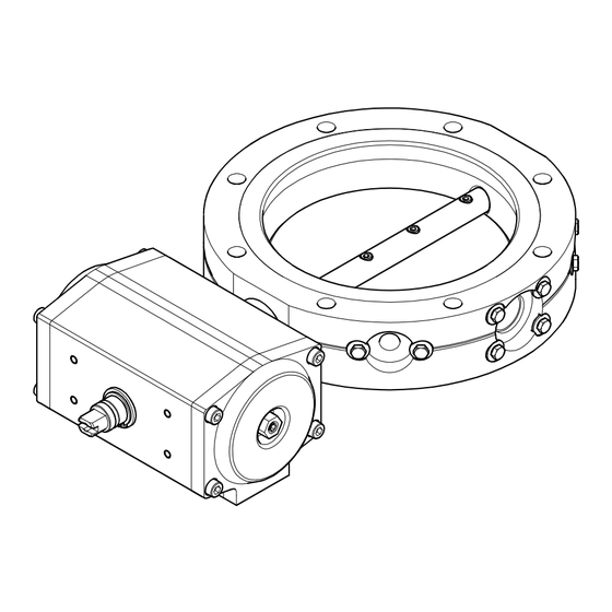
- Page 1 Operating Manual Butterfly Valve pneumatically actuated 21044-PE.4-…. 794861EA (2016-11)
-
Page 2: Product Identification
Product Identification In all communications with VAT, please specify the information on the product nameplate. For convenient reference copy that information into the space provided below: made in Switzerland Fabrication No.: ..-..-../.. -
Page 3: Table Of Contents
Contents Product Identification Validity Intended Use Functional Principle Description Scope of Delivery 1 Safety 1.1 Symbols Used 1.2 Personnel Qualifications 1.3 General Safety Instructions 1.4 Liability and Warranty 2 Technical Data 2.1 Butterfly Valves 2.2 Pilot Valve (Accessory) 2.3 Position Indicator (Accessory) 2.4 Dimensions [mm] 3 Installation 3.1 Accessibility of the Actuator... -
Page 4: Safety
Communicate the safety instructions to all other users. 1.4 Liability and Warranty VAT assumes no liability and the warranty becomes null and void if the end-user or third parties • disregard the information in this document •... -
Page 5: Technical Data
2 Technical Data 2.1 Butterfly Valves 21044-PE.4-000. 21044-PE.4-….. Vacuum connections Axially arranged vacuum connections DN 160 ISO-F Radially arranged vacuum connections 1× DN 25 ISO-KF 2× DN 10 ISO-KF Mounting orientation Cycles to first maintenance 1.5 million Tightness 1×10 mbar l/s Conductance for air Molecular flow 3400 l/s... -
Page 6: Pilot Valve (Accessory)
Nominal voltage 2.2 Pilot Valve (Accessory) Part number 586579 230 VAC / 50 Hz 586580 115 VAC / 60 Hz 586581 24 VAC / 50 Hz 586582 24 VDC Valve type 5/2-way pneumatic valve with NAMUR flange connection Version normally closed Power connection cable socket Degree of protection... -
Page 7: Dimensions [Mm]
2.4 Dimensions [mm] 21044-PE.4-000. DN 25 ISO-KF DN 10 ISO-KF DN 10 ISO-KF 286.5 DN 160 ISO-F DN 160 ISO-F Compressed air connection View A NAMUR flange connection G1/8 G1/8 Threaded tapped hole for code pin (M5×8) Threaded tapped hole for mounting the pilot valve (M5×8) Power connection Connection for position indicator... - Page 8 21044-PE.4-…. 286.5 DN 160 ISO-F DN 160 ISO-F Compressed air connection View A NAMUR flange connection G1/8 G1/8 Threaded tapped hole for code pin (M5×8) Threaded tapped hole for mounting the pilot valve (M5×8) Power connection Connection for position indicator Visual position indicator Valve seat side Leak detection opening...
-
Page 9: Installation
3 Installation DANGER DANGER: overpressure in the vacuum system >2.5 bar KF flange connections with elastomer seals (e.g. O-rings) cannot withstand such pressures. Process media can thus leak and possibly damage your health. Use O-rings provided with an outer centering ring. Caution Caution: vacuum component Dirt and damages impair the function of the vacuum component. -
Page 10: Vacuum Connection Of The 21044-Pe.4-000
3.2 Vacuum Connection of the 21044-PE.4-000. Axially arranged vacuum Section A-A Hex nut connections Washer Claw grip M10/23 Flange Hex nut Seal with Washer centering ring DN 160 ISO-F Claw grip Housing Threaded rod DN 160 ISO-F Seal with centering ring Seal with centering ring Flange... - Page 11 Radially arranged vacuum connections Cover the small flange connections that are not used with blanking flanges of the corresponding nominal diameter. 794861EA (2016-11)
-
Page 12: Vacuum Connections Of The 21044-Pe.4
3.3 Vacuum Connections of Section A-A Hex nut the 21044-PE.4-…. Washer Claw grip M10/19 Flange DN 160 ISO-F Hex nut Washer Claw grip DN 160 ISO-F O-ring Seal with Housing centering ring Threaded rod Flange Seal with centering ring Threaded Claw grip M10/23 Washer... -
Page 13: Compressed Air Connections
3.4 Compressed Air DANGER Connections DANGER: moving parts When the product is connected to the supply media, parts can start moving. Moving parts can catch parts of the body and cause injuries. The connection to the compressed air supply may only be established •... -
Page 14: For Central Compressed Air Control System
Compressed air control via central control system via pilot valve (accessory) → Section 3.4.1 → Section 3.4.2 3.4.1 For Central Compressed Screw in the instant push-in fittings. Air Control System Seal in place? Instand push-in fitting G1/8 To be provided by the end-user 794861EA (2016-11) - Page 15 Push the plastic tubes into the instant push-in fittings until the stop position is reached and check for correct mounting by slightly pulling. Valve Compressed air connection 2 Plastic tube Compressed air connection 4 Butterfly valve open Compressed air admitted via connection 4 closed Compressed air admitted...
-
Page 16: For Pilot Valve (Accessory)
3.4.2 For Pilot Valve Accessories → (Accessory) 3.4.2.1 Voltage Rating Caution Caution: Supply voltage A wrong supply voltage can destroy the product. The supply voltage must correspond to the voltage rating of the pro- duct (→ solenoid coil). If it does not, please contact your local service center. - Page 17 Place the pilot valve on the actuator and tighten the screws. Code pin Cap screws are pre-installed in the pilot valve. Size 4 Pilot valve Hole for code pin Connecting the compressed air inlet Screw the instant push-in fitting into compressed air inlet <1>. Instand push-in fitting Seal in place? G1/4 (Compressed air inlet <1>)
- Page 18 Connecting the compressed If required ... air outlets ... close compressed air outlets <3> and <5> with silencers, ... Silencer Seal in place? G1/8 ( Compressed air outlet <5>) G1/8 (Compressed air outlet <3>) Silencer To be provided by the end-user ...
-
Page 19: Power Connection
… and push the plastic tubes into the instant push-in fittings until the mechanical stop is reached and check for correct mounting by slightly pulling. G1/8 ( Compressed air outlet <5>) G1/8 (Compressed air outlet <3>) 3.4.2.3 Power Connection Mounting the solenoid coil Remove the protective lid. - Page 20 Preparing the cable socket Prepare the cable socket. Insert Ground conductor yellow/green Neutral Phase blue brown 230 VAC, 50 Hz 115 VAC, 60 Hz 24 VAC, 50Hz 24 VDC The polarity need not be taken into consideration in the 24 VDC version.
-
Page 21: Position Indicator (Accessory)
Connecting the cable socket to the solenoid coil Mount the seal, plug in the cable socket, and secure it with the screw. DANGER DANGER: mains voltage (supply voltage) Incorrectly grounded products can be extremely hazardous in the event of a fault. Use only a 3-conductor power cable (supply cable) with protec- tive ground. - Page 22 Slide the base plate of the position indicator on the drive shaft and mount it to the actuator with four hex head screws. Actuator Base Drive shaft The base plate can be rotated by 180°. Hex socket cap screw M5×8 Make a cable according to the following diagram.
- Page 23 Plug in the cable socket and secure it with the coupling ring. DANGER DANGER: mains voltage (supply voltage) Incorrectly grounded products can be extremely hazardous in the event of a fault. Use only a 5-conductor power cable (supply cable) with protective ground.
-
Page 24: Operation
4 Operation Periodically check that the sealing surface of the valve housing and the O-ring of the valve plate are clean and uniformly lubricated. Otherwise, clean and lubricate the sealing surface and O-ring (→ "Minor Maintenance Work", 34). If the valve is operated under harsh or dirty conditions, it should be cleaned / maintained before the specified service time to maintenance (→... - Page 25 Power failure Butterfly valves controlled by the standard pilot valve (→ Accessories) close in the event of a power failure. If such failure occurs and compressed air is admitted, they can be opened and closed via the manual actuator. Manual actuator Butterfly valve "open"...
- Page 26 Compressed air failure In the event of a compressed air failure, the valve plate remains in an undefined position if it was moving. If such failure occurs, manually turn the drive shaft to open or close the Butterfly valve. Precondition: Position indicator removed. Drive shaft Power and compressed air In the event of a power and compressed air failure, the valve plate remains in an...
-
Page 27: Deinstallation
5 Deinstallation Preconditions • Butterfly valve closed • Vacuum system vented 5.1 Power Connections Before connecting or disconnecting the product, turn off the control system. Position indicator Unfasten the coupling ring and pull out the cable socket. Position indcator Coupling ring Pilot valve Unlock the cable socket and pull it out. -
Page 28: Compressed Air Connections
5.2 Compressed Air DANGER Connections DANGER: compressed air Physical injury can result if a pressurized compressed air line is dis- connected. Before doing any work, turn off the compressed air supply and relieve the compressed air lines. Central compressed air system Press the ring towards the valve and pull out the plastic tube. -
Page 29: Vacuum Connections
Press the rings of the compressed air outlets towards the valve and pull out the plastic tubes. Compressed air outlet Compressed air outlet Silencers that have been installed instead of instant push-in fittings need not be removed. 5.3 Vacuum Connections DANGER DANGER: contaminated parts Contaminated parts can be detrimental to health and environment. -
Page 30: 21044-Pe.4-000
5.3.1 21044-PE.4-000. Radially arranged vacuum connections 794861EA (2016-11) - Page 31 Axially arranged vacuum Section A-A Hex nut connections Washer Claw grip M10/23 Flange Seal with centering ring DN 160 ISO-F DN 160 ISO-F Seal with centering ring Flange Threaded rod Claw grip M10/23 Washer Hex nut 794861EA (2016-11)
-
Page 32: 21044
5.3.2 21044-PE.4-…. Section A-A Hex nut Washer Claw grip M10/19 Flange DN 160 ISO-F DN 160 ISO-F Seal with centering ring Flange Threaded rod Claw grip M10/23 Washer Hex nut 794861EA (2016-11) -
Page 33: Maintenance/Repair
Failures due to contamination or wear and tear, as well as expendable parts (e.g. seals, actuator), are not covered by the warranty. VAT assumes no liability and the warranty becomes null and void if the end-user or third parties use the product with accessories, spare parts and consumables not listed in the corresponding product documentation. -
Page 34: Minor Maintenance Work
6.1 Minor Maintenance Work • Precondition Butterfly valve opened DANGER DANGER: moving parts Parts brought into motion by electrical power or compressed air can catch parts of the body and cause injuries. Disconnect the supply media (→ "Deinstallation", 27) and make sure the valve is not inadvertently put into operation. -
Page 35: Major Maintenance Work
6.2 Major Maintenance Work In the following illustrations, the valve is shown without accessories. Precondition • Valve deinstalled (→ • Valve positioned as shown in the illustration 6.2.1 Disassembling the Valve Valve 21044-PE14-000. Deinstalling the actuator and adapter Hex head screw M6×12 Lock washer Adapter Hex socket... - Page 36 Deinstalling the valve plate, shaft and O-rings *) The cap screw are secured with spp (stepstop®) and thus difficult to loosen. 794861EA (2016-11)
- Page 37 Valve 21044-PE.4-….. Deinstalling the actuator and adapter Hex head screw M6×12 Lock washer Adapter Hex socket cap screw M5×20 Shaft Actuator 794861EA (2016-11)
- Page 38 Deinstalling the valve plate, shaft and O-rings *) The cap screw are secured with spp (stepstop®) and thus difficult to loosen. 794861EA (2016-11)
-
Page 39: Cleaning The Valve
6.2.2 Cleaning the Valve DANGER DANGER: cleaning agents Cleaning agents can be detrimental to health and environment. Adhere to the relevant regulations and take the necessary precautions when handling cleaning agents and disposing of them. Consider possible reactions with the product materials (→ Procedure •... - Page 40 Carefully insert the shaft into the housing. Slide one O–ring from the inside of the housing onto the shaft and insert it level into the groove without twisting it. Slide the second O–ring over the first one. Use new O–rings (Spare parts → 60).
- Page 41 Push the shaft in further until the second groove is visible. Second groove Insert the second O–ring level into the groove without twisting it. Lubricate the contact surfaces of the shaft and the visible surface of the O-ring that has been inserted into the groove with high vacuum lubricant FM 090.
- Page 42 Bring the shaft to the axial position shown in the drawing, insert the plug … Plug … and remove excess lubricant from the sealing surface. Remove excess FM 090 from the sealing surface Mounting the O-ring to the valve plate Lubricate the surface of the O-ring by applying a thin, uniform FU 090 film.
- Page 43 … and press it crosswise into the groove as shown in the illustration below. Press the remaining parts of the O-ring level into the groove without twisting the O-ring. Lubricate the visible surface of the O-ring by applying a liberal, uniform FU 090 film.
- Page 44 Lubricating the sealing Position the housing as shown in the illustration, … surface Section A-A ø153 Housing ø153 (VBP160-X) Ø153 (21044-PE.4-000.) Ø155.8 ( 21044-PE.4-….) ø155.8 (VBP160-Z) … rotate the shaft until the milled surface is visible … Milled surface … and lubricate the sealing surface by applying a thin, uniform FU 090 film. Sealing surface 794861EA (2016-11)
- Page 45 Pre-installing the valve plate Turn the housing by 180°... ø153 ( VBP160-X) Ø153 (21044-PE.4-000.) Ø155.8 (21044-PE.4-….) ø155.8 (VBP160-Z) Housing ø153 … and bring the shaft to the position shown in the illustration. Milled surface Carefully insert the valve plate into the housing on the side of milled shaft surface and manually turn in the new hex socket cap screws.
- Page 46 Tilt the valve plate by ≈45° and screw it to the shaft. AF 3 Tighten only slightly Centering and tightening the Bring the valve plate to the "closed" position by turning the square neck valve plate counter-clockwise, e.g. using a wrench. Loosen the cap screws by ≈1/2 turn to allow the valve plate to center itself.
- Page 47 Tighten the cap screws to a torque as shown in the table below. Tightening torque for hex socket screws Valve Screw Size Tightening torque 21044-PE..-…. M4 x 12 3 Nm 21044-PE..-…. M5 x 12 5 Nm 21044-PE44-ADQ1 M5 x 16 10 Nm Mounting the actuator Slide the adapter on the shaft and screw it to the housing.
- Page 48 Make sure the actuator is in its initial position (Butterfly valve "closed"): turn the drive shaft counter-clockwise until the stop position is reached, … Turn until stop is reached Drive shaft Hold stationary … position the actuator on the square neck of the shaft, slide it on the adapter until the stop position is reached, and screw it to the adapter.
-
Page 49: Adjusting The Actuator (Spare Part)
6.2.4 Adjusting the Actuator (Spare Part) Functional principle of the actuator Valve open Valve closed 0° 0° 90° 90° Adjusting screw B Adjusting screw A Adjusting screw B Adjusting screw A If compressed air is admitted to the compressed air connection <4>, the pistons move towards each other and the valve plate opens in position "0°". - Page 50 Determine parallelism. Parallelism ≤0.5 mm: Adjustment completed Parallelism >0.5 mm: Go to step The valve plate is tight at a parallelism ≤5 mm. Measuring point 1 Measuring point 2 0.5 A Measuring point 1 Measuring point 2 <10 mm <10 mm Open the valve.
- Page 51 Untighten counter nut A … Counter nut A AF 4 Hold stationary … and loosen adjusting screw A by 3 … 4 turns. Adjusting screw A Loosen by 3 … 4 turns 794861EA (2016-11)
- Page 52 Untighten counter nut B … Counter nut B AF 4 Hold stationary … and turn in adjusting screw B by 3 … 4 turns. Adjusting screw B Close the valve. 794861EA (2016-11)
- Page 53 Slowly loosen adjusting screw B until the valve plate has reached the valve plate seat. Valve plate seat Adjusting screw B Slowly loosen the screw Determine parallelism: Parallelism ≤0.5 mm: Go to step Parallelism >0.5 mm: Go to step Position valve plate Measuring point 1 Measuring point 1 too high...
- Page 54 Tighten counter nut B with a torque of 4.5 Nm … Counter nut B 4.5 Nm AF 4 Hold stationary … and perform one switching cycle. Determine parallelism: Parallelism ≤0.5 mm: Go to step Parallelism >0.5 mm: Go to step Position valve plate Measuring point 1 Measuring point 1...
- Page 55 Turn in adjusting screw A to the stop without tightening it … Adjusting screw A Turn in the screw without tightening … and tighten counter nut A with a torque of 4.5 Nm. Counter nut A 4.5 Nm AF 4 Hold stationary Perform five switching cycles.
- Page 56 Position valve plate Measuring point 1 Measuring point 1 too high too low • • Untighten counter nut A Untighten counter nut A and go to step • Untighten counter nut B • Turn in adjusting screw B by ≈½ turn, according to the position of the valve plate •...
-
Page 57: Installing The Position Indicator
Tighten counter nut A with a torque of 4.5 Nm … Counter nut A 4.5 Nm AF 4 Hold stationary … and perform five switching cycles. Determine parallelism. Parallelism ≤0.5 mm: Adjustment finished Parallelism >0.5 mm: Go to step 6.2.5 Installing the Position Slide the position indicator on the drive shaft and mount it to the actuator with four Indicator hex socket cap screws. -
Page 58: Valve 21044-Pe.4
6.2.6 Valve 21044-PE.4-….: Lubricate the O-ring by applying a thin, uniform FU 090 film and insert the O-ring Placing the O-ring in the level into the sealing groove without twisting it. Sealing Groove of the Housing Use a new O-ring (→ "Spare Parts", 60). -
Page 59: Accessories
7 Accessories Pilot valve Ordering number 230 VAC, 50 … 60 Hz 586579 115 VAC, 50 … 60 Hz 586580 24 VAC, 50 … 60 Hz 586581 24 VDC 586582 Further information → Position indicator Ordering number Load capacity 230 V, 1 A 587850 Further information →... -
Page 60: Spare Parts
8 Spare Parts Seal kit Ordering number for 21044-PE.4-000., comprising 580255 1 O-ring, FPM75, ø139.06×5.34 2 O-rings, FPM75, ø10×3 4 hexagon socket head cap screws, M4×12-A2-70-spp for 21044-PE.4-ABA., comprising 580259 1 O-ring, FPM75, ø139.06×5.34 2 O-rings, FPM75, ø10×3 1 O-ring, FPM75, ø158.1×5.34 4 hexagon socket head cap screws, M4×12-A2-70-spp others on request... -
Page 61: Returning The Product
10 Returning the Product WARNING WARNING: forwarding contaminated products Contaminated products (e.g. radioactive, toxic, caustic or biological hazard) can be detrimental to health and environment. Products returned should preferably be free of harmful substances. Adhere to the forwarding regulations of all involved countries and forwarding companies and enclose a duly completed declaration of contamination .
Need help?
Do you have a question about the 21044-PE 4 Series and is the answer not in the manual?
Questions and answers