Advertisement
Quick Links
This user's guide describes the evaluation module (EVM) for the Texas Instruments TPS26620,
TPS26621, TPS26622, and TPS26623 devices. This document provides configuration information and test
setup details for evaluating the TPS26620-23 devices. The EVM schematic, board layout, and bill of
materials (BOM) are included.
...................................................................................................................
1
....................................................................................................................
2
...................................................................................................................
3
Schematics
4
General Configurations
5
EVM Board Assembly Drawings and Layout Guidelines
6
Bill Of Materials (BOM)
1
TPS26620-23EVM Schematic
2
3
J4 = 1-2 Position, Current Limit (800 mA) and Auto-Retry
4
Output Short-Circuit Protection
5
6
7
8
1
TPS26620-23EVM Options and Setting
2
Input and Output Connector Functionality
3
Test Points Description
4
Jumper and LED Descriptions
5
TPS26620-23EVM Oscilloscope Setting for Current Limit Test
6
TPS26620-23EVM Jumper Setting for Current Limits
7
TPS26620-23EVM Oscilloscope Setting for Output Short Circuit Protection
8
Trademarks
All trademarks are the property of their respective owners.
1
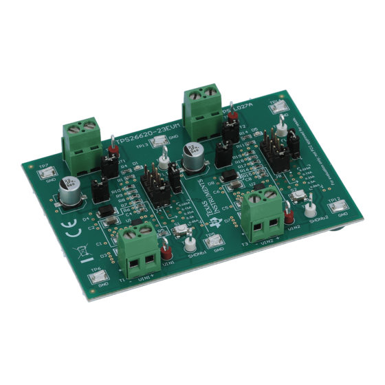
Introduction
The TPS26620-23EVM allows reference circuit evaluation of TI's TPS2662X. The TPS2662X devices are
4.5- to 57-V, 800-mA industrial eFuse with integrated back-to-back FETs, programmable undervoltage,
overvoltage, input reverse polarity, overcurrent and inrush current protection features.
SLVUBA1 - October 2017
Submit Documentation Feedback
ADVANCE INFORMATION
TPS26620-23 Evaluation Module
Contents
.....................................................................................................
....................................................................................................
List of Figures
.............................................................................................
..........................................................................................
............................................................................................
.................................................................................
..............................................................................
..................................................................................
..............................................................................
List of Tables
..................................................................................
................................................................................
.....................................................................................................
.............................................................................................
......................................................................................
Copyright © 2017, Texas Instruments Incorporated
...............................................................
.............................................................
.......................................................
..................................................................
........................................
TPS26620-23 Evaluation Module
User's Guide
SLVUBA1 - October 2017
1
2
3
4
9
11
3
5
7
8
9
9
10
10
2
4
4
4
6
6
7
11
1
Advertisement

Related Manuals for Texas Instruments TPS26620-23


Summary of Contents for Texas Instruments TPS26620-23
-
Page 1: Table Of Contents
This user’s guide describes the evaluation module (EVM) for the Texas Instruments TPS26620, TPS26621, TPS26622, and TPS26623 devices. This document provides configuration information and test setup details for evaluating the TPS26620-23 devices. The EVM schematic, board layout, and bill of materials (BOM) are included. -
Page 2: Introduction
PLCs Description The TPS26620-23EVM enables full evaluation of the TPS26620-23 devices. This EVM has two independent channels (CH1 and CH2) where two devices can be evaluated together. CH1 is configured to test OVP cutoff versions TPS26620 and TPS26621 and CH2 is configured to test OV clamp versions TPS26622 and TPS26623. - Page 3 VIN2 VOUT2 TPS26622DRCR 22µF Green 0.022µF 7.50k 13.3k 26.7k 44.2k 267k TP12 TP13 TP14 Copyright © 2017, Texas Instruments Incorporated Figure 1. TPS26620-23EVM Schematic SLVUBA1 – October 2017 TPS26620-23 Evaluation Module Submit Documentation Feedback Copyright © 2017, Texas Instruments Incorporated...
- Page 4 A DPO2024 or equivalent, three 10× voltage probes and a DC current probe. 4.2.4 Loads One resistive load or equivalent which can tolerate up to 2-A DC load at 24 V. TPS26620-23 Evaluation Module SLVUBA1 – October 2017 Submit Documentation Feedback Copyright © 2017, Texas Instruments Incorporated...
-
Page 5: Evm Setup With Test Equipment
(CR) mode, not in the constant current (CC) mode. Test Setup and Connections Figure 2 shows a typical test setup for the TPS26620-23 EVM. Connect T1 to the power supply and T2 to the load. >... - Page 6 8. After the oscilloscope triggers, turn off the load. 9. Connect the oscilloscope to CH2 and verify the same behavior on CH2 by repeating the procedure. TPS26620-23 Evaluation Module SLVUBA1 – October 2017 Submit Documentation Feedback Copyright © 2017, Texas Instruments Incorporated...
- Page 7 Trigger source = Channel 2 Trigger level = 10 V Trigger polarity = Negative Trigger mode = Single sequence Time base 2 ms/div 2 ms/div SLVUBA1 – October 2017 TPS26620-23 Evaluation Module Submit Documentation Feedback Copyright © 2017, Texas Instruments Incorporated...
- Page 8 4. Use either thick wire or a screw driver to short the output to ground and verify the output short-circuit response as shown in Figure Figure 4. Output Short-Circuit Protection TPS26620-23 Evaluation Module SLVUBA1 – October 2017 Submit Documentation Feedback Copyright © 2017, Texas Instruments Incorporated...
-
Page 9: Tps26620-23Evm Top Side Placement
Figure 8 show the component placement and layout of this EVM. Figure 5. TPS26620-23EVM Top Side Placement Figure 6. TPS26620-23EVM Bottom Side Placement SLVUBA1 – October 2017 TPS26620-23 Evaluation Module Submit Documentation Feedback Copyright © 2017, Texas Instruments Incorporated... -
Page 10: Tps26620-23Evm Top Layer Routing
ADVANCE INFORMATION EVM Board Assembly Drawings and Layout Guidelines www.ti.com Figure 7. TPS26620-23EVM Top Layer Routing Figure 8. TPS26620-23EVM Bottom Layer Routing TPS26620-23 Evaluation Module SLVUBA1 – October 2017 Submit Documentation Feedback Copyright © 2017, Texas Instruments Incorporated... -
Page 11: Tps26620-23Evm Bill Of Materials
FID1, FID2, FID3 Fiducial mark. There is nothing to buy or mount. Fiducial R9, R18 44.2k RES, 44.2 k, 1%, 0.1 W, 0603 0603 CRCW060344K2FKEA Vishay-Dale SLVUBA1 – October 2017 TPS26620-23 Evaluation Module Submit Documentation Feedback Copyright © 2017, Texas Instruments Incorporated... - Page 12 STANDARD TERMS FOR EVALUATION MODULES Delivery: TI delivers TI evaluation boards, kits, or modules, including any accompanying demonstration software, components, and/or documentation which may be provided together or separately (collectively, an “EVM” or “EVMs”) to the User (“User”) in accordance with the terms set forth herein.
- Page 13 FCC Interference Statement for Class B EVM devices NOTE: This equipment has been tested and found to comply with the limits for a Class B digital device, pursuant to part 15 of the FCC Rules. These limits are designed to provide reasonable protection against harmful interference in a residential installation.
- Page 14 【無線電波を送信する製品の開発キットをお使いになる際の注意事項】 開発キットの中には技術基準適合証明を受けて いないものがあります。 技術適合証明を受けていないもののご使用に際しては、電波法遵守のため、以下のいずれかの 措置を取っていただく必要がありますのでご注意ください。 1. 電波法施行規則第6条第1項第1号に基づく平成18年3月28日総務省告示第173号で定められた電波暗室等の試験設備でご使用 いただく。 2. 実験局の免許を取得後ご使用いただく。 3. 技術基準適合証明を取得後ご使用いただく。 なお、本製品は、上記の「ご使用にあたっての注意」を譲渡先、移転先に通知しない限り、譲渡、移転できないものとします。 上記を遵守頂けない場合は、電波法の罰則が適用される可能性があることをご留意ください。 日本テキサス・イ ンスツルメンツ株式会社 東京都新宿区西新宿6丁目24番1号 西新宿三井ビル 3.3.3 Notice for EVMs for Power Line Communication: Please see http://www.tij.co.jp/lsds/ti_ja/general/eStore/notice_02.page 電力線搬送波通信についての開発キットをお使いになる際の注意事項については、次のところをご覧ください。http:/ /www.tij.co.jp/lsds/ti_ja/general/eStore/notice_02.page 3.4 European Union 3.4.1 For EVMs subject to EU Directive 2014/30/EU (Electromagnetic Compatibility Directive): This is a class A product intended for use in environments other than domestic environments that are connected to a low-voltage power-supply network that supplies buildings used for domestic purposes.
- Page 15 Notwithstanding the foregoing, any judgment may be enforced in any United States or foreign court, and TI may seek injunctive relief in any United States or foreign court. Mailing Address: Texas Instruments, Post Office Box 655303, Dallas, Texas 75265 Copyright © 2017, Texas Instruments Incorporated...
- Page 16 IMPORTANT NOTICE FOR TI DESIGN INFORMATION AND RESOURCES Texas Instruments Incorporated (‘TI”) technical, application or other design advice, services or information, including, but not limited to, reference designs and materials relating to evaluation modules, (collectively, “TI Resources”) are intended to assist designers who are developing applications that incorporate TI products;...
Need help?
Do you have a question about the TPS26620-23 and is the answer not in the manual?
Questions and answers