SKF LMC 301 Series Operating Instructions Manual
Lubrication monitor controller
Hide thumbs
Also See for LMC 301 Series:
- Operating instructions manual (120 pages) ,
- Installation manual (28 pages) ,
- Operating instructions manual (116 pages)
Table of Contents
Advertisement
Quick Links
Advertisement
Table of Contents

Related Manuals for SKF LMC 301 Series


Summary of Contents for SKF LMC 301 Series
- Page 1 Operating instructions Lubrication Monitor Controller according to Low-Voltage Directive 2014/35/EU of series LMC 301 for control of up to three pumps, each with an SKF single-line centralized lubrication system containing one to three channels. 951-180-067-EN Version 05 2023/08/31...
-
Page 2: Eu Declaration Of Conformity In Accordance With Directive 2014/35/Eu An- Nex Iv On The Use Of Electrical Equipment Within Certain Voltage Limits
EU Declaration of Conformity EU Declaration of Conformity in accordance with Directive 2014/35/EU Annex IV on the use of electrical equipment within certain voltage limits The manufacturer Lincoln Industrial Corporation, 5148 North Hanley Road, St. Louis MO, U.S.A. hereby declares under its sole responsibility conformity of the following electrical device/equipment Designation: Lubrication Monitor Controller... -
Page 3: Declaration Of Conformity Pursuant To The Electrical Equipment (Safety) Regulations 2016 (No. 1101)
The manufacturer Lincoln Industrial Corporation, 5148 North Hanley Road, St. Louis MO, U.S.A. hereby declares under its sole responsibility conformity of the electrical device/equipment with all relevant United Kingdom legislation at the time of placing on the market. The authorized representative for the compilation of the technical documentation is SKF (U.K.) Limited, 2 Canada Close, Banbury, Oxfordshire, OX16 2RT, GBR. Designation:... -
Page 4: Masthead
Masthead Masthead Manufacturer ○ Use of non-original SKF spare parts Training Lincoln Industrial Corporation ○ Faulty planning or design of the central- SKF conducts detailed training in order to www.lincolnindustrial.com enable the maximum safety and efficiency. www.skf.com/lubrication ized lubrication system... -
Page 5: Table Of Contents
Table of contents Table of contents EU Declaration of Conformity in accordance with Directive 2014/35/EU An- nex IV on the use of electrical equipment within certain voltage limits ..2 UK Declaration of Conformity pursuant to the Electrical Equipment (Safety) Regulations 2016 (No. 1101) ..............3 Masthead .....................4 Explanation of symbols and signs ...............9 Safety instructions .............. - Page 6 Table of contents Electrical connection ................31 6.2.11 Pump 1 Timings ..................56 5.3.1 General ....................31 6.2.12 Operator level without password access ..........56 5.3.2 Terminal board 100-240 VAC .............33 6.2.13 Local Admin (setter) or supervisor with password access ....57 5.3.3 Terminal board 24 VDC ................34 6.2.14 Information ....................60 5.3.4 Line routing ...................35...
- Page 7 Table of contents Malfunctions, causes, and remedies ........... 79 Fuse replacement .................79 Display of error notifications via fault LED .........80 Display of fault notifications on the screen ........80 Controller unit- Commissioning malfunctions ........84 System malfunction ................85 Measures in response to malfunctions ..........88 Spare parts/accessories ..............
-
Page 9: Explanation Of Symbols And Signs
Explanation of symbols and signs Explanation of symbols and signs Activities that present specific hazards to Read the instructions completely and follow Possible symbols persons or material assets are indicated with all operating instructions and the warning Meaning Symbol warnings. and safety instructions. - Page 10 Explanation of symbols and signs Abbreviations and conversion factors Instructions placed on a unit, machine, or Abbreviations equipment, such as: regarding ounce o Rotation arrow approx. approximately pound per square inch °C degrees Celsius horsepower o Fluid connection labels second pound o Warnings dB (A)
-
Page 11: Safety Instructions
1. Safety instructions 1. Safety instructions 1.1 General safety instructions regular intervals.If protective and safety 1.2 General behavior when handling the mechanisms must be removed, they product must be installed immediately follow- The operator must ensure that the instruc- ing conclusion of work and checked for tions are read and fully understood by all ○... -
Page 12: Qualified Technical Personnel
Product training can also be performed by hazards. The definition of qualified personnel SKF in exchange for costs incurred. and the prohibition against employing non- qualified personnel are laid down in DIN VDE 0105 and IEC 364. -
Page 13: Electric Shock Hazard
1. Safety instructions 1.4 Electric shock hazard 1.6 Assembly, maintenance, faults, de- 1.5 Operation commissioning and disposal ○ The following must be observed while working on the product. ○ All information within this manual and All relevant persons (operating personnel, WARNING supervisors) must be informed of the activity the information within the referenced... -
Page 14: Foreseeable Misuse
(one to three main lines) SKF ○ Other units of the machine/ the vehicle prohibited. Particularly prohibited are: single-line centralized lubrication system. -
Page 15: Disclaimer Of Liability
○ Installation of non-original tor if necessary. The operator must supplement these docu- SKF components ments with applicable regulations for the ○ Non-compliant usage country of use. The documentation must be included if the product is transferred to a ○... -
Page 16: Notes On The Type Plate
1. Safety instructions 1.13 Note on UL mark 1.12 Notes on the type plate 1.16 Note on CE marking The type plate provides important data such The CE marking is based on the require- The UL Mark certifies that the as the type designation, order number, and ments of the applied Directives: product has UL certification of... -
Page 17: Residual Risk
1. Safety instructions 1.18 Residual risk Table 1 Residual risk Remedy Life cycle: Assembly/commissioning/operation/setup and retrofit Electric shock due to defective or incor- • Inspect the power lead for damage before starting the product rectly connected power lead on power supply or load relay •... -
Page 18: Overview/System Description
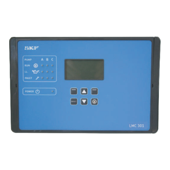
2. Overview/System description 2. Overview/System description Display, Fig. 2 PUMP FAULT PUMP POWER RESET FAULT LMC 301 POWER RESET LMC 301 CAUTION! PUMP FAULT Do not use rigid electrical conduits. POWER RESET LMC 301 ACHTUNG! keine starren Elektroinstallations- rohre verwenden. The customer installs the cable glands and the cable sets provided by the customer. - Page 19 2. Overview/System description Status overview and triggering an additional lubrication Symbol Status Function Overview States Pressing the down arrow key provides a status overview of the pumps and zones P1Z1 (P1Z1 = pump 1/zone 1 to max. P3Z3 pump 3/zone 3). P1Z2 P1Z3 P1Z1 States/Times...
- Page 20 2. Overview/System description Display and control elements of control screen Symbol Designation Function Display o Menu display/Display of values and parameters/Fault display o The right bar ( ) indicates that the menu extends beyond the current display PUMP PUMP Pump/main line A / B / C per pump Pumps A B C Max.
-
Page 21: Lmc 301 Controller Unit
2. Overview/System description 2.1 LMC 301 controller unit Display elements of the control screen The SKF LMC 301 Controller is used to con- Symbol Status Function trol SKF single-line centralized lubrication systems. o The system was stopped by pressing the Reset key and can... -
Page 22: General Design Of A Single-Line Centralized Lubrication System
Selecting menu item <<Condition on Deliv- ery>> resets all stored values and settings to The following descriptions applies to a sin- The SKF LMC 301 Controller offers configu- factory settings. gle-line centralized lubrication system with rations for the following zone settings for two zones (two main lines). -
Page 23: Design Of The Equipment
2. Overview/System description 2.2.1 Design of the equipment )See Figure 3 It can likewise be designed as a NO-contact a signal to the controller that the changeover or an NC contact. Pressure is built up from the pump element is finished. The controller then switches off Another system design involves using 2/2 (1) via the mechanical pressure relief valve the pump and the mechanical pressure relief... - Page 24 2. Overview/System description System diagrams of single-line centralized lubrication systems, Fig. 3 This causes the relubrication metering 2/2 directional solenoid valves and relief valve devices to relieve pressure, and lubricant is delivered to the respective lubrication lines. Zone 1 (main line 1) The active solenoid valve (4 or 5) switches to an open state once its holding time has elapsed.
-
Page 25: Technical Data
3. Technical data 3. Technical data 3.1 General technical data Characteristics, design Mounting position Vertical, see Page 15 Dimensions (LxWxH) 270 x 170 x 90 mm Display 60x30 mm128x64 pixels Ambient conditions Altitude ≤ 2000 m / DC ≤ 5000 m Ambient/operating temperature -10 to + 50 °C Ambient/operating temperature... - Page 26 3. Technical data Characteristics, design Characteristics, design Protection and monitoring Output rating of relays Current limit Sustained short-circuit-proof Connection directly to relay 01/02 100-240 VAC/max. 15 A Overload-proof/open-circuit-proof Connection directly to relay 01/02 24 VDC/max. 15 A Output terminal strip 01 to 08 24 VDC;...
-
Page 27: Delivery, Returns, And Storage
4. Delivery, returns, and storage 4. Delivery, returns, and storage 4.1 Checking the delivery General notes Immediately after receipt, the delivery must WARNING be checked for completeness according o The product(s) can be enveloped in plastic to the shipping documents. Any transport Personal injury/property damage film to provide low-dust storage. -
Page 28: Assembly
5. Assembly 5. Assembly 5.1 General 5.2 Setup and attachment Only qualified technical personnel may The packaging material must be preserved The product should be protected from hu- install, operate, maintain, and repair the until any discrepancies are resolved. midity and vibration, and should be mounted LMC 301 Lubrication Monitor Controller. -
Page 29: Port Dimensions, Assembly Holes, And Minimum Mounting Dimensions
5. Assembly 5.2.1 Port dimensions, assembly holes, and minimum mounting dimensions Fig. 4 Minimum mounting dimensions A = Width 330 mm B = height 450 mm C = depth 350 mm... -
Page 30: Opening The Controller Unit
5. Assembly 5.2.3 Minimum mounting dimensions 5.2.2 Opening the controller unit ) See Figures 4 and 5 To ensure enough space for maintenance • Open the controller unit, place it on the • Insert a flat tip screwdriver (1) with a work and possible disassembly of the prod- surface, and roughly align it. -
Page 31: Electrical Connection
5. Assembly 5.3 Electrical connection 5.3.1 General The controller unit is supplied with 100- Consult Chapter 4, Technical Data, for the NOTICE electrical characteristics of the controller 240 V AC voltage or optionally with 24 V unit. The connections on the controller unit DC voltage. - Page 32 5. Assembly NOTICE NOTICE NOTICE The Lubrication Monitor Controller On the controller unit's electrical A suitable all-pole appliance switch or pow- contains electronic components that connections, ensure that appropri- er switch (min 10A) that meets the applica- can be destroyed by accidental elec- ate measures prevent interference ble requirements of IEC 60947-1 and IEC trostatic charge or discharge (ESD).
-
Page 33: Terminal Board 100-240 Vac
5. Assembly 5.3.2 Terminal board 100-240 VAC Legend to Figure 6 Connections on mainboard, design 100-240 VAC, Fig. 6 NOTICE Pos. Description Chap- Only one operating voltage (24 VDC or 100-240 VAC) can be connected to terminal strip 4.1 or 4.2. Do not operate two different voltages within a terminal strip! Power supply 5.3.6 1a Internal 100-240 VAC connection... -
Page 34: Terminal Board 24 Vdc
5. Assembly 5.3.3 Terminal board 24 VDC Legend to Figure 7 Connections on mainboard, 24 V DC design, Fig. 7 NOTICE Pos. Description Chap- Only one operating voltage (24 VDC or 100-240 VAC) can be connected to terminal strip 4.1 or 4.2. Do not operate two different voltages within a terminal strip! Power supply 5.3.6 Digital inputs... -
Page 35: Line Routing
5. Assembly 5.3.4 Line routing 5.3.5 Connecting the wires ) see Figures 6 and 7 ) see Figures 6 and 7, item 1, and Fig. 8 Fig. 8 The lines are laid through cable glands at- The wires on the terminal strips for: ○... -
Page 36: Power Supply 100
5. Assembly 5.3.6 Power supply 100 ... 240 VAC and 24 VDC 5.3.7 Load switching relay ) see Figure 6, item 1, and Fig. 9 ) see Figure 7, item 1, and Fig. 10 ) See Figures 6/7, item 11, and Fig. 11 Terminal diagram 100-240 VAC, Fig. -
Page 37: Terminal Strip For Relay Outputs
5. Assembly 5.3.8 Terminal strip for relay outputs )see Figures 6/7, item 4, and Figs. 12 and 13 The outputs on the terminal strip X4 are provided Connection example for relay outputs, Fig. 12 for downstream relays or loads installed by the Relay outputs, connection example 24 VDC, customer. -
Page 38: Terminal Strip For Digital Inputs
5. Assembly 5.3.10 Terminal strip for analog-capable 5.3.9 Terminal strip for digital inputs inputs )see Figures 6/7, item 2, and Figure 14 )see Figures 5/6, item 3, and Figure 15 The digital inputs are provided for: Terminal strip for digital inputs, Fig. 14 Terminal strip for analog-capable inputs, Fig. -
Page 39: Adding An Additional Io Connection To Rs485 Interface
5. Assembly 5.3.11 Adding an additional IO connection to RS485 interface )See Figures 6/7, item 8 )See Figures 16/17 Setting IO addresses, Fig. 16 Daisy chaining with external IO boards, Fig. 17 Another IPCB communication connection can be established using the two RS485 Off... -
Page 40: Configuration By Operator/Local Admin
The software can also be downloaded as • Enter the password "skfmc2013" )The LMC 301 software installs automati- freeware from the SKF website. After in- stalling the program, data transfer occurs cally. SKF recommends not starting any via the USB interface in the controller. -
Page 41: Configuration Of The Controller Unit Via The Display On The Controller Unit
6. Configuration by operator/local admin 6.2 Configuration of the controller unit via the display on the controller unit 6.2.1 Structure of a lubrication cycle Display, Fig. 20 System with 3/2 zone directional solenoid valve System with 2/2 zone directional solenoid valve Work cycle time Work cycle time Lubrication time =... -
Page 42: States/Overview
6. Configuration by operator/local admin 6.2.3 Display and control elements of When entering the password, there is a dif- 6.2.2 States/Overview control screen ferentiation between Local Admin (customer access) and Supervisor (only service staff, no After switching on the supply voltage, the customer access). - Page 43 6. Configuration by operator/local admin Status overview and triggering an additional lubrication Symbol Status Function Pressing the down arrow key provides a status overview of the pumps and zones Overview States (P1Z1 = pump 1/zone 1 to max. P3Z3 pump 3/zone 3). P1Z1 P1Z2 P1Z3...
- Page 44 6. Configuration by operator/local admin Display and control elements of control screen Symbol Designation Function Display o Menu display/Display of values and parameters/Fault display o The right bar ( ) indicates that the menu extends beyond the current display PUMP PUMP Pump/main line A / B / C per pump Pumps A B C...
- Page 45 6. Configuration by operator/local admin Display elements of the control screen Symbol Status Function Stopped/OFF o The system was stopped by pressing the Reset key and can be restarted by briefly pressing the Running key. Pause o Respective lubrication zone is in interval time Wait Temperature o Waiting period temperature Waiting...
-
Page 46: Menu Navigation For Operators Without Password Access
6. Configuration by operator/local admin 6.2.4 Menu navigation for operators without password access Login settings Enter Password Login settings Enter Password Password correct Please Enter Password Your locked in as Set PW local admin to Continue Local Operator Set PW Supervisor 0000 User settings Unit Settings... - Page 47 6. Configuration by operator/local admin Setting options for operators without password access, Fig. 22 Pump 1 Timings Zone 1 Settings Zone 2 Settings Zone 1 Settings Lube load Zone 2 Settings [Normal Cycle Set] << >> [Heavy Cycle Set] Lube load [Normal Cycle Set] <<...
-
Page 48: Menu Navigation For Local Admins With Password Access
6. Configuration by operator/local admin 6.2.5 Menu navigation for local admins with password access Enter Password Login settings Login settings Login settings Password correct Enter Password Please Enter Password Enter Password Your locked in as to Continue Set PW local admin Set PW local admin Local Operator 0000... - Page 49 6. Configuration by operator/local admin Setting options for local admins, Fig. 23 Note! Menu only upon activation of the Zone 1 Settings Pump Timings 3/2 zone valve Zone Relief Time Zone 2 Settings Lube Load [ 60] s (System configuration => Pump setting => [Normal Cycle Set] <<...
-
Page 50: Main Menu
6. Configuration by operator/local admin 6.2.6 Main menu The main menu shows the following options: Pump 1 Timings Main menu, Fig. 24 )see Chapter 6.2.11 Login settings Main menu )See Chapter 6.2.7 In this menu, the timing of the pump and Login settings The <Login settings>... -
Page 51: General Setting Options Without (With) Password Access
6. Configuration by operator/local admin 6.2.7 General setting options without (with) password access User settings Step Button Display Description User settings - Set units and menu language Overview States • Press <Menu control key> P1Z1: )You will be taken to the main menu Main menu •... - Page 52 6. Configuration by operator/local admin User settings Step Button Display Description User settings - Set units and menu language • Use <up arrow key > to select the Unit Settings menu item [Imperial/Metric] User settings Select Unit Settings • Press <Control key Select> [Metric •...
-
Page 53: Setting Options For Local Admins (Setters) With Password Access
Set PassWord local admin for customer's personnel (change password) Login settings o Set PW Supervisor for SKF Service and SKF dealers (change password) Enter Password o If the password has already been entered (open lock), the menu item Log Off is also... -
Page 54: Changing The Password
• Enter current password (see previous chapter) • Use <down/up arrow key> to select password level Set PassWord local admin (customer Login settings Enter Password service) or Set PW Supervisor (SKF Service) Set PW local admin • Press <Control key OK> Set PW Supervisor Log Off )You will enter the Set PW local admin or Set PW Supervisor menu. -
Page 55: Device Settings
6. Configuration by operator/local admin 6.2.10 Device settings Device settings Step Button Display Description Device settings- Display, system date, and system time Main menu • Use <down/up arrow key> to select Device settings Login settings • Press <Control key OK> User settings Device settings )You will enter the Device Settings menu. -
Page 56: Pump 1 Timings
6. Configuration by operator/local admin 6.2.11 Pump 1 Timings 6.2.12 Operator level without password access General - see Pages 41/42 and Pages 46/47 Up to three pumps can be connected to the LMC 301 Controller; the maximum amount The following entries can be made here: of zones (main lines) that the Controller can o <<Normal Cycle Set>>... -
Page 57: Local Admin (Setter) Or Supervisor With Password Access
6. Configuration by operator/local admin 6.2.13 Local Admin (setter) or supervisor with password access Pump 1 Timings - see Pages 43/44 and Pages 48 to 50 Step Button Display Description Local Admin password Factory setting: 1000 Pump 1 Timings User Settings- without password level •... - Page 58 6. Configuration by operator/local admin Pump 1 Timings Step Button Display Description Pump 1 timings- with password level Local Admin or Supervisor • Use < down/uparrow key> to select Pump 1 Timings Main menu • Press <Control key OK> Login settings User settings Device settings Pump 1 Timings...
- Page 59 6. Configuration by operator/local admin Pump 1 Timings Step Button Display Description Pump 1 timings- with password level Local Admin or Supervisor Zone 1 Settings )The following menu items are available: Lube Load o Lube Load: Selection between Normal Cycle Set and Heavy Cycle Set. The two lubrication [Normal Cycle Set] settings differ in terms of the duration of cycle time.
-
Page 60: Information
6. Configuration by operator/local admin 6.2.14 Information The information menu simply presents information. Parameters cannot be changed, and error notifications cannot be cleared. Information Step Button Display Description Information menu - without password level • Use <down/up arrow key> to select Information •... -
Page 61: Examples Of Single-Line Systems
6. Configuration by operator/local admin 6.2.15 Examples of single-line systems Several examples of single-line systems sys- tems with an LMC 301 Controller are listed below and can be used as the basis for local admins to make their settings. The individual examples are divided into three sections. -
Page 62: 2-Zone Single-Line Centralized Lubrication System With 2/2 Directional Solenoid Valves And 1 Pressure Switch
6. Configuration by operator/local admin 6.2.16 2-zone single-line centralized lubrication system with 2/2 directional solenoid valves and 1 pressure switch )See Figures 25 and 26 LMC 301, electrical terminal diagram, Fig. 25 Design The example applies to a single-line central- ized lubrication system with two zones (zone 1/zone 2 (line 1/line 2)). - Page 63 6. Configuration by operator/local admin System design, Fig. 26 (pressure monitoring PT, voltage) X3, terminal + (pressure monitoring PT, ground) X3, terminal + (pressure monitoring PT, signal) X3, terminal I 1 (fill level monitoring) X3, terminal I 3 Pump motor, max.
- Page 64 6. Configuration by operator/local admin Customer programming of the LMC 301 unit via the controller display and controller keys Programming via the LMC 301 display Step Button Display Description The following requirements are met: • User settings have been made according to Chapter 6.2.5 •...
- Page 65 6. Configuration by operator/local admin Pump 1 Timing and Cycle Control Step Button Display Description Pump 1 Timing User Settings )You will enter the Zone 1 Settings menu. )The following menu items are available o <<Normal Cycle Set>> or <<Heavy Cycle Set>>. Entry of lubrication intensity, normal or heavy cycle set o Normal Cycle Counts: Entry of cycle time for normal cycle set o Heavy Cycle Counts: Entry of cycle time for increased lubricant demand (longer pump...
- Page 66 6. Configuration by operator/local admin Pump 1 Timing and Cycle Control Step Button Display Description Pump 1 Timing User Settings • Use <down arrow key> to select the Heavy Cycle Counts menu item • Press <Control key Select> Zone 1 Settings •...
- Page 67 6. Configuration by operator/local admin Pump 1 Timing and Cycle Control Step Button Display Description Pump 1 Timing User Settings- Zone 2 Settings • Use <down/up arrow key> to select the Zone 2 Settings menu item Pump 1 Timings • Press <Control key OK> Pump Timings Zone 1 Settings •...
-
Page 68: 2-Zone Single-Line Centralized Lubrication System With 3/2 Directional Solenoid Valves And 2 Pressure Switches
6. Configuration by operator/local admin 6.2.17 2-zone single-line centralized lubrication system with 3/2 directional solenoid valves and 2 pressure switches )See Figures 27 and 28 LMC 301, electrical terminal diagram, Fig. 27 Design The example applies to a single-line central- ized lubrication system with two zones (zone 1/ zone 2 (line 1/line 2)). - Page 69 6. Configuration by operator/local admin System design, Fig. 28 Pressure monitoring PT2, signal, X3, + Pressure monitoring PT2, signal, X3, I1 Pressure monitoring PT2, ground X3, - Fill level monitoring X3, I3 (pump motor, max. 8 amp) X4, 01 Zone 1, X4, 02 Zone 2, X4, 05...
- Page 70 6. Configuration by operator/local admin Customer programming of the LMC 301 unit via the controller display and controller keys Programming via the SKF Flex-Control display Step Button Display Description The following requirements are met: • User settings have been made according to Chapter 6.2.5 •...
- Page 71 6. Configuration by operator/local admin Pump 1 Timing and Cycle Control Step Button Display Description Pump 1 Timing User Settings )You will enter the Zone 1 Settings menu. )The following menu items are available o <<Normal Cycle Set>> or <<Heavy Cycle Set>>. Entry of lubrication intensity, normal or heavy cycle set o Normal Cycle Counts: Entry of cycle time for normal cycle set o Heavy Cycle Counts: Entry of cycle time for increased lubricant demand (longer pump...
- Page 72 6. Configuration by operator/local admin Pump 1 Timing and Cycle Control Step Button Display Description Pump 1 Timing User Settings • Use <down arrow key> to select the Heavy Cycle Counts menu item • Press <Control key Select> Zone 1 Settings •...
- Page 73 6. Configuration by operator/local admin Pump 1 Timing and Cycle Control Step Button Display Description Pump 1 Timing User Settings- Zone 2 Settings • Use <down/up arrow key> to select the Zone 2 Settings menu item Pump 1 Timings • Press <Control key OK> Pump Timings Zone 1 Settings •...
-
Page 74: Operation/Decommissioning And Disposal
7. Operation/decommissioning and disposal 7. Operation/decommissioning and disposal 7.1 User-configurable setting options )Explanation of display symbols and con- trols - see Chapter 6.2.3. The customer can access the menus stored Single-line centralized lubrication systems in the Main menu (see Fig. 29) and make NOTICE with an LMC 301 Controller typically operate some settings. -
Page 75: Temporary Shutdown
7. Operation/decommissioning and disposal 7.2 Temporary shutdown o Perform visual inspection Temporary shutdown is performed by dis- Device settings o Switch on the product connecting the electrical supply connections. )see Chapter 6.2.10 Observe the instructions in the chapter “As- In this menu, the display properties of the 7.4 Shutdown and disposal sembly”... -
Page 76: Maintenance
Contact the SKF Service department in case NOTICE of problems with the controller unit. Only original SKF spare parts may be used. Unauthorized alterations and the use of non-original spare parts and accessories Dismantling of the product or individual... -
Page 77: Maintenance Schedule
8. Maintenance 8.2 Maintenance schedule The maintenance intervals are system- fined by the system manufacturer/operator specific and are affected by environmental based on the specific operating conditions. influences such as dust and temperature. The maintenance intervals are therefore de- Inspection Dispose of electronic components and plastic Pos. -
Page 78: Battery Replacement
To avoid possible loss of data, replace the A software update can be loaded onto the Battery replacement, Fig. 30 lithium button cell battery after no later than LMC 301 controller unit using the SKF NGL 24 months. program. The battery replacement procedure should... -
Page 79: Malfunctions, Causes, And Remedies
The following tables provide an overview of possible malfunctions and their causes. NOTICE NOTICE Contact the SKF Service department if you cannot remedy the malfunction. The LMC 301 Controller contains Before replacing a defective fuse, electronic components that can be first remedy the cause of the malfunction. -
Page 80: Display Of Error Notifications Via Fault Led
9. Malfunctions, causes, and remedies 9.2 Display of error notifications via fault LED Fault display, Table 2 Display Fault status Fault output Cause FAULT LED is off No error ERROR LED flash- Pump1/Zone1 = A Error has occurred in the indicated area. ing red Pump1/Zone1 = B Read error notification on display. - Page 81 9. Malfunctions, causes, and remedies Code Fault message signal Error [010] Pump Offline Output pump not available [011] Pump Config Output pump wrong settings [012] Remote Address Output pump address multiple [013] LL Sensor Offline Input Low Level not available [014] LL Sensor Config Input Low Level wrong settings...
- Page 82 9. Malfunctions, causes, and remedies Code Fault message signal Error [032] Spray Offline Output Spray not available [033] Spray Config Output Spray wrong settings [034] Spray Address Output Spray address multiple [035] Alarm Out Offline Output Alarm not available [036] Alarm Out Config Output Alarm wrong settings [037]...
- Page 83 9. Malfunctions, causes, and remedies Code Fault message signal Error [100] Mtr Protection On Motor protection on [101] Int Temp Offline Input internal temperature not available [102] Int Temp Config Input internal temperature wrong settings [103] Int Temp Address Input internal temperature address multiple [104] Temp Out of Range Temperature out of Range...
-
Page 84: Controller Unit- Commissioning Malfunctions
9. Malfunctions, causes, and remedies 9.4 Controller unit- Commissioning malfunctions Fault Cause Remedy Motor fails to start • Check that motor connection is wired correctly o Motor incorrectly connected when the operating • Inspect pump timing as described in Chapter o Pump timing not parameterized voltage is switched 6.2.10... -
Page 85: System Malfunction
9. Malfunctions, causes, and remedies 9.5 System malfunction Fault Cause Remedy • Check mains connection • Check mains plug/cable and connect properly if necessary o No operating voltage on motor • Check operating voltage on motor o Phase absent Motor fails to start •... - Page 86 Incorrect rotational direction of motor • If opening pressure is incorrect or if the pressure-regulating valve is damaged, replace the valve. Only use original SKF spare parts. • If contaminated, clean the pressure-regulating valve o or check valve on pump element de-...
- Page 87 Pressure-regulating valve does not • If opening pressure is incorrect or if the pressure-regulating valve is close damaged, replace the valve Only use original SKF spare parts. • If contaminated, clean the pressure-regulating valve • Clean or replace reversing valve.
-
Page 88: Measures In Response To Malfunctions
9. Malfunctions, causes, and remedies 9.6 Measures in response to malfunctions Fault message signal Cause Remedy o Grease reservoir Low-level signal • Fill grease reservoir empty o Line broken No pressure build-up at • Inspect lubrication system, replace broken lubrication line if necessary o Pump motor is pump pressure switch •... -
Page 89: Spare Parts/Accessories
The customer installs the cable glands and the cable sets provided by the customer. The customer is therefore reliable for their correct installation. Blade-type fuse FK1 3A (32 V) acc. to ISO 8820-3 3V lithium button cell batteryModel CR 3032 236-11066-1 LMC 301 software http://www.skf.com/LMC301 Warning labels (- see page 12 246-078-289... -
Page 90: System Configuration
11. System configuration System configuration 11.1 Menu navigation for system configuration - pump settings Login settings Enter Password Login settings Pump Output Login settings Password correct Please Enter Password Enter Password Output Type Your locked an as to Continue Enter Password [normally open] Set PW local admin 0000... - Page 91 11. System configuration Setting options for pump settings, Fig. 32 Pump Output Only with the following activated: Lube Control Mode Sensor at Pump Set. Remout Manuale Lube Lube Control Mode => Pressure-controlled Output Type Sensor Type EInput Type Lube Control Moder [normally open] <<...
-
Page 92: Menu Navigation For System Configuration - Zone Settings
11. System configuration 11.1.1 Menu navigation for system configuration - zone settings Login settings Login settings Enter Password Login settings Please Enter Password Password correct Enter Password Enter Password to Continue Your locked an as Set PW local admin Set PW local admin 0000 Subvisor Set PW Supervisor... - Page 93 11. System configuration Setting options for zone settings, Fig. 34 Timings Lube Loade Release/Counter Input Type Control Mode Input Type [ << time controlled >> << Counder ctrld >> ] [ << normally open >> << normally closed >> << disabled >> ] [ <<...
-
Page 94: Menu Structure For System Configuration
)You will enter the System configuration All essential controller and system settings menu. System configuration )You will be asked "Lubrication will be for an SKF single-line centralized lubrication Lubrication will be stopped system are made in the system configuration stopped- Continue?" Continue? menu level. -
Page 95: Amount Of Pumps
11. System configuration 11.3 Amount of pumps Selecting the amount of pumps Step Button Display Description Select the amount of pumps - only in Supervisor password level • Open the System configuration menu System configuration • Use <down /up arrow key> to select Amount of pumps menu Amount of pumps Setting the pump )Entry of the maximum number of pumps for the entire lubrication system... -
Page 96: Setting The Pump
11. System configuration 11.4 Setting the pump Pump settings => Pump 1 settings =>Pump settings Step Button Display Description Configuring the pumps - only in Supervisor password level • Open the System configuration menu (see Chapter 7.3) System configuration • Use <down/up arrow key> to select Pump settings (1-3) menu Amount of pumps •... - Page 97 11. System configuration Pump settings => Pump settings => System Type Step Button Display Description • Use < down/up arrow key> to select the desired setting • Press <Control key OK> • You will enter the selected menu. System Type In this menu, the lubrication system is assigned to the pump that has already been selected.
- Page 98 11. System configuration Pump settings => Pump settings => Lube Control => Pump Output Step Button Display Description Lube Control Entry and monitoring of the lubrication system are done in this menu • Press <Control key OK> Lube Control )The following settings are available: Output Pump o Pump Output - Specification of the pump-specific parameters Lube Control Mode...
- Page 99 11. System configuration Pump settings => Pump settings => Lube Control => Lube Control Mode => Sensor at Pump Set. Step Button Display Description Lube Control Mode The type of pressure relief is specified as time controlled or pressure controlled in this menu. •...
- Page 100 11. System configuration Pump settings => Pump settings => Lube Control => Sensor at Pump Set. Step Button Display Description With transducer: Sensor at Pump • Press <down arrow key> Select Sensor Type The following settings are available: [transducer 4-20 mA o Input - the first or second input is configurable as an analog value (AI) Input [0.00 ] AI...
- Page 101 11. System configuration Pump settings => Pump settings => Lube Control=> Remote Manual Lube Step Button Display Description Remote Manual Lube Settings for the Remote Manual Lube system input • Press <Control key OK> )You will enter the Remote Manual Lube menu The following settings are available: Select Input Type...
- Page 102 11. System configuration Pump settings => Pump settings =>Relief Settings Step Button Display Description Relief Settings For zones with 3/2 directional solenoid valves (zone valves), the zone valves are actuated once again when the pump is off after a complete lubricating cycle is finished (zone 1 to max. zone 3). Time-dependent relief of the main lubrication line (pump to zone valves) occurs. •...
- Page 103 11. System configuration Pump settings => Pump settings => Filling/Low Level => Monitoring Step Button Display Description Filling/Low Level Select and configure the fill level switch • Press <Control key OK> )You will enter the Filling/Low Level menu The following settings are available: Filling/Low Level o Monitoring - see Step 5.1...
- Page 104 11. System configuration Pump settings => Pump settings => Filling/Low Level => Alarm Step Button Display Description Alarm Setting for the Alarm system output • Press <Control key OK> )You will enter the Alarm Settings menu Alarm • Press <Control key Select> Select Output Type •...
- Page 105 11. System configuration Pump settings => Pump settings => Filling/Low Level =>Inputs Step Button Display Description Inputs Selection of fill level switch - input type • Press <Control key OK> Inlets )You will enter the Inputs menu Input No. LL Type Select •...
- Page 106 11. System configuration Pump settings => Pump settings => Filling/Low Level =>Inputs Step Button Display Description Inputs Selection of fill level switch - input type With normally closed and normally open contacts: • Press <down arrow key> • Press <Control key Select> Inlets Select •...
- Page 107 11. System configuration Pump settings => Pump settings => Filling/Low Level =>Timings Step Button Display Description Timings Set the delay time for low level signal and filling • Press <Control key OK> )You will enter the Timings menu Timings Select •...
- Page 108 11. System configuration Pump settings => Pump settings => Motor Protection Step Button Display Description Motor Protection Connection settings for the external auxiliary contact of the motor circuit breaker • Press <Control key OK> )You will enter the Motor Protection Settings menu Motor Protection The following settings are available: Motor Protection Type...
- Page 109 11. System configuration Pump settings => Pump settings =>Temperature Control => Internal Sensor Step Button Display Description Temperature Control Configure the internal sensor (controller board) or external sensor Temperature Control • Press <Control key OK> Int. Sensor Setting )You will enter the Temperature Settings menu Select Exter.
- Page 110 11. System configuration Pump settings => Pump settings =>Temperature Control => Internal Sensor => External Sensor Step Button Display Description Temperature Control Set internal sensor (controller board) or external sensor If internal sensor is enabled: Temperature Limits • Use <down arrow key> to select Temperature Limit Over temperature )The following settings are available: Select...
- Page 111 11. System configuration Pump settings => Pump settings =>Temperature Control => External Sensor Step Button Display Description Save With transducer: External Sensor • Press <down arrow key> Sensor Type Back ) The following settings are available: [transducer 4-20 mA Input o Input [0.00 ] AI o Minimal Value...
-
Page 112: Zone 1 Settings (Main Line Settings)
11. System configuration 11.5 Zone 1 Settings (main line settings) Pump settings => Zone 1 Settings Step Button Display Description Configuring the zones - only in Supervisor password level • Open the System configuration menu (see Chapter 7.3) System configuration •... - Page 113 11. System configuration Pump settings => Zone 1 Setting => Cycle Control => Timings Step Button Display Description Zone 1 Settings/ Cycle Control Cycle control for the respective zone )The following settings are available: o Timings Cycle Control o Release/Counter Select o Lube Load Timings...
- Page 114 11. System configuration Pump settings => Zone 1 Settings => Release/Counter => Lube Load Step Button Display Description Release/Counter Trigger the lubricating cycle • Press <Control key OK> Release/Counter )You will enter the Release/Counter menu Select • Press <Control key Select> Input Type •...
- Page 115 11. System configuration Pump settings => Zone 1 Settings => Lube Control=> Relief Valve Step Button Display Description Zone 1 Settings/Lube Control Settings for relief valve, zone 1 • Use <down/up arrow key> to select the Lube Control menu Lube Control •...
- Page 116 11. System configuration Pump settings => Zone 1 Settings => Lube Control => Relief Valve => Press. Sensor at EOL Step Button Display Description Zone 1 Settings/Lube Control Zone 1 Pressure sensor at end of line (EOL) Select • Press <Control key Select> •...
- Page 117 11. System configuration Pump settings => Zone 1 Settings => Lube Control =>Flow Sensor => Main Line Timings Step Button Display Description Zone 1 Settings/Lube Control Zone 1 Flow Sensor • Use <Down arrow key> to select Sensor Mode Flow Sensor •...
- Page 118 11. System configuration Pump settings => Zone 1 Settings => Lube Control =>Flow Sensor => Main Line Timings Step Button Display Description Zone 1 Settings/Lube Control Zone 1 Flow Sensor • Use <Down arrow key> to select Input No.1 Flow Sensor •...
- Page 119 11. System configuration Pump settings => Zone 1 Settings => Lube Control =>Main Line Timings => Post Sprayer Step Button Display Description Monitoring Time Monitoring of pressure build-up time Select • Press <Control key Select> Main Line Timings • Use <down/up arrow key> to enter the monitoring time for zone 1 •...
- Page 120 11. System configuration Pump settings => Zone 1 Settings => Lube Control=> Alarm Step Button Display Description Zone 1 Settings/Lube Control Zone 1 Alarm • Use <down arrow key> to select Alarm Alarm • Press <Control key OK> Select Output Type )You will enter the Alarm menu [normally open] •...
-
Page 121: Set Params To Default
11. System configuration 11.6 Set Params to Default NOTICE Resetting (Set Params to Default) loads the default values for the selected lubrication system. Set Params to Default Step Button Display Description System configuration / Set Params to Default Activating Set Params to Default resets the selected lubrication system. Entries made by the customer or service staff are overwritten. -
Page 122: China Rohs Table
16. Appendix China RoHS table 有毒害物质或元素 (Hazardous substances) 部件名称 铅 汞 镉 六价铬 多溴联苯 多溴二苯醚 (Part Name) Hexavalent Polybrominated Polybrominated Lead Mercury Cadmium Chromium biphenyls diphenyl ethers (Pb) (Hg) (Cd) (Cr(VI)) (PBB) (PBDE) 用钢和黄铜加工的零件 (Components made of machining steel and brass) 本表格依据SJ/T11364的规定编制... - Page 123 Notes...
- Page 124 Lincoln Industrial Corporation 5148 North Hanley Road, St. Louis, MO U.S.A. www.lincolnindustrial.com www.skf.com/lubrication 951-180-067-EN Version 05 2023/08/21...
Need help?
Do you have a question about the LMC 301 Series and is the answer not in the manual?
Questions and answers