Table of Contents
Advertisement
Quick Links
Advertisement
Table of Contents

Subscribe to Our Youtube Channel
Related Manuals for SKF CAHB-20


Summary of Contents for SKF CAHB-20
- Page 1 Installation, operation and maintenance manual CAHB-20 Linear Actuator Read this manual before installing, operating or maintaining this actuator. Failure to follow safety precautions and instructions could cause actuator failure and result in serious injury, death or property damage.
-
Page 2: Table Of Contents
10 .1 .1 Dismantling of CAHB-20 . . . . . . . . . . . . . . . . . -
Page 3: General Information
General information Information on this manual Note! Emphasizes useful hints and rec- This manual provides important information on how to work with ommendations as well as information the actuator safely and efficiently . for efficient and trouble-free operation . The manual is part of the actuator, must always be kept in the actuator’s direct proximity and should be available for the personnel at any time . -
Page 4: Limitation Of Liability
In case the actuator is customised, the actual product delivered may be different from what is described in the manual . In this case, ask SKF for any additional instructions or safety precautions relevant to these actuators . We reserve the right to make technical modifications to the actua-... -
Page 5: Warranty Terms
The applicable and effective warranty terms are those contained in the manufacturer’s terms and conditions of sale . Customer service SKF Customer Service is always available to provide technical infor- mation and answer questions . See the contact information for SKF Customer Service on the... -
Page 6: Safety
Safety This chapter provides an overview of important safety precautions and information necessary for safe and trouble-free installation, operation and maintenance . Disregarding this Manual and safety precautions specified therein may result in considerable danger and possible serious injury or death . -
Page 7: Personnel Requirements
dent prevention guidelines and environmental precautions regula- tions applicable to the site of the system’s installation: • Inform themselves of applicable industrial safety precautions and determine additional hazards that arise due to the specific work- ing conditions prevailing at the site where the actuator is installed using risk assessment . -
Page 8: Specific Dangers
• A professional electrician based on his/her professional training, know-how and experience as well as knowledge of the applicable standards and regulations is able to perform work on electrical systems and to detect and avoid possible dangers on his/her own . The professional electrician has been trained for the special location where he/she works and knows the relevant standards and regulations . -
Page 9: Safety Equipment
Moving components W a r n i n g Danger of injury caused by moving components! Rotating and/or linearly moving components can cause severe injury . Therefore: • Do not work on or place any of your body, hands, or arms near moving components . - Page 10 . If clutch activates, switch off power immediately . C a u t i o n Clutch activation can cause the limit switch to stop functioning . If this happens, have an SKF engineer adjust it so that it again operates properly .
-
Page 11: Changes And Modifications On The Actuator
Changes and modifications on the actuator To avoid hazardous situations and to ensure optimal performance, do not make any changes or modifications to the actuator unless they have been specifically authorized by SKF . -
Page 12: Technical Data
Technical data Note! The technical data (dimensions, weight, output, connec- tion values etc .) can be found in the enclosed drawings and data sheets († Appendix) . Operating conditions Environment Information Value Unit Temperature range –40 to +85 °C Relative atmospheric humidity, maximum up to 85 (no build up of condensation) Duration (intermittent) -
Page 13: Structure And Function
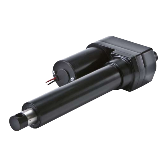
Structure and function Overview CAHB-20 Fig. 2 Cable Motor part Gearbox Front hinge head Push tube Guide tube Rear hinge head... -
Page 14: Brief Description
Brief description Overview Fig. 3 This actuator is to be used exclusively for installation into a dynamic centric-compression or tensile-loaded lift . The linear actuator consists of a motor part (3) and a linear unit (5), connected with each other by a bayonet joint . The actuator consists of a direct current motor with spur gear which sets in motion a trapezoidal sliding spindle system with shaft joint . -
Page 15: Special Features
C a u t i o n Clutch activation can cause the limit switch to stop functioning . If this happens, have an SKF engineer adjust it so that it again operates properly . C a u t i o n Incorrect activation of clutch could cause actuator damage . -
Page 16: Connections
The limit switch makes it possible to control the stroke of the linear unit by internal setting . W a r n i n g If mechanical overload protection unit activates, the limit switch can malfunction. Contact the SKF to adjust the setting of limit switch . -
Page 17: Potentiometer
4.6.2 Potentiometer The potentiometer provides a signal indicating the postion of the lin- ear actuator . There are two types of settings for the potentiometer wire . • Linear actuator with potentiometer and limit switch units: colours of wire are white, red and black († Fig. 11) . •... -
Page 18: Transport, Packaging And Storage
Note storage requirements for return transport to the manu- facturer († Chapter Storage) . Transport inspection The CAHB-20 linear actuator is delivered as one packaged unit in a box or on pallets . Check the delivery for completeness and damage due to transport immediately upon receipt . -
Page 19: Return To The Manufacturer
Return to the manufacturer Proceed as follows for the return transport: Dismantle the actuator if necessary ( † Chapter Dismantling) . Pack the actuator in its original packaging . Follow storage condi- tions († Chapter Storage) . page 2 . Send to manufacturer . -
Page 20: Storage
Storage Pack the actuator in its original packaging for storage . • Do not store outside . • Dry and dust-free storage . • Keep away from any aggressive media . • Protect from UV radiation . • Avoid mechanical vibrations . •... -
Page 21: Installation And First Operation
Installation and first operation Authorized personnel • The installation and first start of operation may only be conducted by qualified personnel . • Work on the electric system may only be performed by trained electricians . W a r n i n g Electrical equipment Electric shock and moving parts hazards Serious injury or death can be caused by touching live electrical... -
Page 22: Installation Location
Install in a location where the actuator is not exposed to strong UV radiation or corrosive or explosive air media . Installation The CAHB-20 linear actuator is attached to two elements via the hinge heads . Connect the hinge heads ( 1 and 2, Fig. - Page 23 Ensure that the applied force on the fastening bolts is always cen- trically directed on the actuator († Fig. 7) . Fig. 7 W a r n i n g Risk of injury and material damage due to incorrect installation! During installation, do not subject the actuator to side-impact or to turning forces .
-
Page 24: Inspections Prior To First Operation
Inspections prior to first operation Prior to the first operation, a professional electrician must perform and document the following tests and readings: • Check visual condition • Function check of operating features and safety features • Reading of protective conductor resistance •... -
Page 25: Operation
Operation Safety D a n g e r Risk of crushing! Actuator may cause serious injuries while moving . Therefore: • Ensure that there are no persons in the stroke area of the actuator while in operation . • Take note of maximum permissible operating data for the actuator . -
Page 26: Action Before Operation
C a u t i o n Material damage through overheating! Therefore: • Only use control integrated thermal switch . † technical data in Chapter 11 • Never exceed nominal load . ( Appendix) . • Always adhere to idle times and operating times . (†... -
Page 27: Action During Operation
7.3.1 Normal operation During normal operation, the linear actuator lifts and lowers the elements that are connected with the CAHB-20 linear actuator via the hinge head . The linear actuator can directly connect to electrical grid or be controlled by an operating element . - Page 28 C a u t i o n Material damage due to incorrect set up of the limit switch! Therefore: • Select limit switch or other electrical component that is ade- quate for the rating voltage and current of linear actuator (†...
-
Page 29: Disengagement In Case Of Emergency
Disengagement in case of emergency In hazardous situations, all movements of the actuator must be stopped as quickly as possible and the power supply must be turned off . Proceed as follows in hazardous situations: Immediately engage emergency shut-off, if present, or cut off power for actuator . -
Page 30: Maintenance
. Spare parts The CAHB-20 linear actuator is not designed for repair work by the customer . All warranty and service claims become void without notice if any screws on the linear actuator have been manipulated . -
Page 31: Maintenance Plan
Use only genuine spare parts from the manufacturer . • Spare parts in/on the actuator may only be replaced by SKF . The actuator must be dismantled and sent to the manufacturer . The address is listed on the cover back . -
Page 32: Maintenance Work
Maintenance work 8.3.1 Cleaning To be performed by operator C a u t i o n Damage due to incorrect cleaning! Therefore: • Do not use any aggressive cleaning agents . Water used for cleaning including the chemical additives must be pH-neutral . •... -
Page 33: Check Of Visual Condition
Check hinge hole for cracks, deformation and broken pieces Check stainless steel tube for scratches and indentations Notify processor or SKF in case of damage If there is no damage and the processors/manufacturer has not communicated any concerns, reconnect the actuator to the power supply . -
Page 34: Malfunctions
Malfunctions The following chapter describes potential causes for malfunctions and the work that is necessary to restore operation . In the event of frequent malfunctions, shorten the maintenance intervals . Contact the manufacturer concerning malfunctions which are not solved by the following suggestions . Personnel •... - Page 35 D a n g e r Optional devices Risk of injury and material damage due to incorrect repair of malfunction Therefore: • Never loosen the screws on the linear actuator or try to open the linear actuator . • In the event of a malfunction that cannot be fixed by adhering to the subsequent notices, dismantle the actuator and send it to the manufacturer for repair .
-
Page 36: Malfunction Table
Malfunction table Malfunction Possible cause To repair malfunction To be repaired by Linear actuator doesn't move No supply voltage Check power supply Professional electrician Lack of plug contact or plug has not Plug contacts: Operator been inserted properly Device control unit, control of voltage network . -
Page 37: Start Of Operation After Fixing Malfunction
Start of operation after fixing malfunction After the malfunction has been fixed, perform the steps from the chapter Installation prior to restart . -
Page 38: Dismantling
Dismantling Personnel • The dismantling may only be carried out by specifically qualified personnel . • Work on the electric system may only be performed by profes- sional electricians . D a n g e r Electrical equipment Electric shock and moving parts hazards Serious injury or death can be caused by touching live electrical components and by unexpected movement of the actuator . -
Page 39: Dismantling
10.1 Dismantling 10.1.1 Dismantling of CAHB-20 Separate actuator from energy supply ( † Chapter Operation † Disengagement in case of emergency) . Secure elements of the application in such a fashion, that no loads can impact the hinge heads . -
Page 40: Appendix
Appendix Technical data sheets The following 4 pages are a reprint from PUB MT/P2 10694 EN · April 2010... - Page 41 Linear actuator CAHB–20 series Features • ACME screw drive • Stainless steel extension tube • Steel protection tube • Enhanced corrosion resistance • Mechanical overload protection (clutch) • Lubricated for service life • Robust, designed for tough environment • Self-locking •...
- Page 42 CAHB–20 series Linear actuators DC versions Connecting diagram Dimensional drawing Basic configuration (dashed line for optional limit switch) 12/24 V DC 24,5 73,5 30(55*) 11,5 15,5 Black +0,1 †13,1 –0 +0,1 †13,1 –0 Actuator 47,5 161,5 Different rear attachment C0–C5 Without limit swicth: RED (+) &...
- Page 43 CAHB–20 series Linear actuators DC versions Performance diagrams Current consumption (A) Speed (mm/s) 12 V DC 24 V DC 1 000 1 500 2 000 2 500 1 000 1 500 2 000 2 500 Load (N) Load (N) Speed-load diagram Current-load diagram Dimensional drawing Optional potentiometer...
- Page 44 SKF brings innovative solutions to OEMs and production facilities in every major industry world- wide. These five competence areas include bearings and units, seals, lubrication systems, mechatronics (combining mechanics and electronics into intelligent systems), and a wide range of services, from 3-D...
- Page 45 Notes...
- Page 46 SKF brings innovative solutions to OEMs and production facilities in every major industry world- wide. These five competence areas include bearings and units, seals, lubrication systems, mechatronics (combining mechanics and electronics into intelligent systems), and a wide range of services, from 3-D...
Need help?
Do you have a question about the CAHB-20 and is the answer not in the manual?
Questions and answers