SKF LMC 301 Series Installation Manual
Lubrication monitor controller
Hide thumbs
Also See for LMC 301 Series:
- Operating instructions manual (124 pages) ,
- Operating instructions manual (154 pages) ,
- Operating instructions manual (120 pages)
Table of Contents
Advertisement
Quick Links
Quick Setup/Installation Guide
Lubrication Monitor Controller
of series LMC 301
for control of up to three pumps, each with an SKF Single Line / Progressive
and Dual Line centralized lubrication system containing one to three main lines.
This description is intended as an overview of installation for the LMC 301 Lubrication
Monitor Controller. It does not replace the assembly instructions for the LMC 301 controller.
These are contained on the enclosed USB stick. The assembly instructions can be ordered in
paper format from SKF Lubrication Systems Germany GmbH or Lincoln Industrial, One
Lincoln Way, St. Louis, MO 63120-1578 USA.
In case of discrepancies between the assembly instructions and the Quick Guide, the information
in the assembly instructions takes precedence.
ATTENTION!
The comprehensive assembly instructions (see page 2) are included on the enclosed USB stick
and can be downloaded from our homepage http://www.skf.com/LMC301/.
Version 03
951-150-029-EN
Advertisement
Table of Contents

Subscribe to Our Youtube Channel
Related Manuals for SKF LMC 301 Series


Summary of Contents for SKF LMC 301 Series
- Page 1 Lubrication Monitor Controller of series LMC 301 for control of up to three pumps, each with an SKF Single Line / Progressive and Dual Line centralized lubrication system containing one to three main lines. This description is intended as an overview of installation for the LMC 301 Lubrication Monitor Controller.
-
Page 2: Table Of Contents
Quick Setup/Installation Guide for Lubrication Monitor Controller LMC 301 Contents Quick Setup/Installation Guide Information symbols within the text 1. Safety instructions Coniguration of several IO boards to master slaves General safety instructions General behavior when handling Menu navigation for operators Symbol Meaning without password access... -
Page 3: Safety Instructions
Product training can also be performed by be clearly defined and observed. Uncer- tions are read and fully understood by all per- SKF in exchange for costs incurred. tainty seriously endangers safety. sons tasked with working on the product or o Protective and safety mechanisms cannot who supervise or instruct such persons. -
Page 4: Assembly/Maintenance/Malfunction/ Decommissioning/Disposal
Contaminated or unsuitable lubricants o Take appropriate measures to ensure that module) are powered via 100 to 240 o Installation of non-original SKF moving/detached parts are immobilized mains provided by the customer. They must components during the work and that no body parts can... -
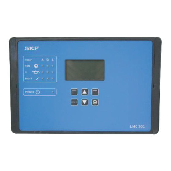
Page 5: Overview
Quick Setup/Installation Guide for Lubrication Monitor Controller LMC 301 2. Overview Display and control elements of control screen Symbol Designation Function Display o Menu display / Display of values and parameters / Fault notification o The right bar ( ) indicates that the menu extends beyond the current display PUMP Pump / Main line A / B / C per pump PUMP... - Page 6 Quick Setup/Installation Guide for Lubrication Monitor Controller LMC 301 Status Overview and triggering an additional lubrication Symbol Status Function Overview States Press the arrow key to receive a status overview of the pumps resp. zones P1Z1 (P1Z1 = Pump 1/Zone1 to max. P3Z3 Pump 3/Zone 3). P1Z2 P1Z3 States/Timer P1Z1...
-
Page 7: Technical Data
Quick Setup/Installation Guide for Lubrication Monitor Controller LMC 301 3. Technical data 3.1 General technical data Characteristics, design Characteristics, design Electronic consuming General Iternal fuse (LMC-Controller) Mounting position Vertical, refer to graphic, see page 14 Dimensions (L x W x H) 10.6299 x 6.6929 x 3.5433 in Input AC Input voltage 100-240 VAC (50/60Hz) -
Page 8: Assembly
Quick Setup/Installation Guide for Lubrication Monitor Controller LMC 301 4. Assembly 4.1 Port dimensions, assembly holes, and minimum mounting dimensions Fig. 1 10.31 PUMP 9.72 FAULT POWER RESET LMC 301 Minimum mounting dimensions A = width: 12.99 in 10.67 B = height 17.72 in C = depth 13.78 in... -
Page 9: Electrical Connection
Quick Setup/Installation Guide for Lubrication Monitor Controller LMC 301 4.4 Electrical connection 4.6 Connecting wires 4.4.1 General ) see Figures 4 and 5, item 1, and Figure 3 WARNING ATTENTION! The wires on the terminal strips for: o power connection (item 1) Electric shock o digital outputs (item 2) De-energize the control unit prior to... -
Page 10: Terminal Board 100 To 240 Vac
Quick Setup/Installation Guide for Lubrication Monitor Controller LMC 301 4.7 Terminal board 100 to 240 VAC Legend to Figure 4 Connections on mainboard, 100 to 240 VAC design, Fig. 4 Item Description BA-Chapter 4.7.2 Power supply Cable glands for valves/motor Cable glands for power supply/interface Internal 100 to 240 VAC con- nection for the AC/DC power... -
Page 11: Power Supply 100 To 240 Vac And 24 Vdc
Quick Setup/Installation Guide for Lubrication Monitor Controller LMC 301 4.7.2 Power supply 4.7.3 Terminal strip for relay outputs 100 to 240 VAC and 24 VDC )see Figures 4/5, item 4, and Figures 9 to 10 ) see Figure 4, item 1, and Fig. 6 Terminal diagram 100 to 240 V AC, Fig. -
Page 12: Terminal Strip For Digital Inputs
Quick Setup/Installation Guide for Lubrication Monitor Controller LMC 301 4.7.5 Terminal strip for digital inputs 4.7.6 Terminal strip for analog capable inputs )see Figures 4/5, item 2, and Figure 11 )see Figures 4/5, item 3, and Fig. 12 Terminal strip for digital inputs, Fig. 11 Set IO addresses, Fig. -
Page 13: Coniguration By Operator/Local Admin
USB interface during this period. in the controller. No entries can be made and the symbol o SKF recommends this procedure for initial shows a closed lock installations. To change the configuration, select the Menu o Configuration of the system using the menu item using the control key . -
Page 14: General Setting Options
Quick Setup/Installation Guide for Lubrication Monitor Controller LMC 301 5.2.3 General setting options User settings The main menu shows the following options: Display Description Login settings The <Login settings> menu is used to manage User settings - Set units and menu language access to the menus with a password. -
Page 15: Menu Structure For System Coniguration
System coniguration ATTENTION! Display Description SKF Service menu System coniguration - Amount of pumps, Pump settings, Set Params to Default This level is password-protected and can- - only in Supervisor password level not be accessed from the operator level or )Requirements: Supervisor password level is the Local Admin level. - Page 16 In the following please find further notes re- 1 2 3 4 garding the connection of the adapter cable. Master SKF takes a separate voltage supply for each board as given. Adapterkabel o SKF takes a separate voltage supply for each board as given.
- Page 17 Quick Setup/Installation Guide for Lubrication Monitor Controller LMC 301 5.3 Menu navigation for operators without password access Fig. 18 Login settings Enter Password Enter Password Password correct Login settings Please enter Password You are are logged in as Set PW local admin to Continue Local Operator Set PW Supervisor...
- Page 18 Quick Setup/Installation Guide for Lubrication Monitor Controller LMC 301 5.4 Menu navigation for local admins with password access Fig. 19 Login settings Login settings Login settings Login settings Enter Password Enter Password Passwort correct Enter Password Please enter Password You are logged in as Set PW local admin Set PW local admin to Continue...
-
Page 19: Single Line
Quick Setup/Installation Guide for Lubrication Monitor Controller LMC 301 6. System configuration Single Line pump settings with Supervisor password 6.1 Menu navigation for system coniguration - Fig. 20 Login settings Pump Output Login settings Login settings Enter Password Password correct Output Type Enter Password Main Menu... - Page 20 Quick Setup/Installation Guide for Lubrication Monitor Controller LMC 301 Single Line zone settings 6.2 Menu navigation for system coniguration - Fig. 21 Login settings Login settings Enter Password Login settings Main Menu Password correct Please Enter Password Enter Password Login settings to Continue Your locked an as Set PW local admin...
- Page 21 Quick Setup/Installation Guide for Lubrication Monitor Controller LMC 301 Progressive pump settings with Supervisor password 6.3 Menu navigation for system coniguration - Fig. 22 Lube Control Login settings Pump Output Login settings Login settings Enter Password Enter Password Password correct Output Type Main Menu Please enter Password...
-
Page 22: Menu Navigation For System Coniguration
Quick Setup/Installation Guide for Lubrication Monitor Controller LMC 301 - Progressive zone settings 6.4 Menu navigation for system coniguration Fig. 23 Login settings Login settings Enter Password Login settings Main Menu Please Enter Password Password correct Enter Password Login settings to Continue Your locked an as Set PW local admin... - Page 23 Quick Setup/Installation Guide for Lubrication Monitor Controller LMC 301 Dual Line settings with Supervisor password 6.5 Menu navigation for system coniguration - Fig 24 Lubricating settings Login settings Pump Output Login settings Login settings Enter Password Output Type Enter Password Password correct [ <<normally closed>>...
- Page 24 Quick Setup/Installation Guide for Lubrication Monitor Controller LMC 301 6.6 Menu navigation for Dual Line Zone control 6.6.1 Zone Control with two 3/2 solenoid valves or with EMU 2 Fig. 26 Login settings Login settings Login settings Enter Password Enter Password Password correct Main Menu Please enter Password...
- Page 25 Quick Setup/Installation Guide for Lubrication Monitor Controller LMC 301 6.6.2 Zone Control with EMU 3 Fig. 27 Login settings Login settings Login settings Enter Password Enter Password Password correct Main Menu Please enter Password You are logged in Set PW local admin to continue as Supervisor Set PW Supervisor...
- Page 26 Quick Setup/Installation Guide for Lubrication Monitor Controller LMC 301 6.6.3 Zone Control with DU1 Fig. 28 Login settings Login settings Login settings Enter Password Enter Password Password correct Main Menu Please enter Password You are logged in Set PW local admin to continue as Supervisor Login settings...
- Page 27 Quick Setup/Installation Guide for Lubrication Monitor Controller LMC 301 6.6.4 Zone Control with MA/MP Fig. 29 Login settings Login settings Login settings Enter Password Enter Password Password correct Main Menu Please enter Password You are logged in Set PW local admin to continue as Supervisor Set PW Supervisor...
- Page 28 Not all lubricants are suitable for use in centralized lubrication systems. SKF does offer an inspection service to test customer supplied lubricant to deter- mine if it can be used in a centralized system. SKF lubrication systems or their components are not approved for use with gases, liquefied gases, pres- surized gases in solution and fluids with a vapor pressure exceeding normal atmospheric pressure (1013 mbar) by more than 0.5 bar at their maximum...
Need help?
Do you have a question about the LMC 301 Series and is the answer not in the manual?
Questions and answers